
Related Manuals for Thunder Scientific 2500 series


Summary of Contents for Thunder Scientific 2500 series
- Page 1 OPERATION AND MAINTENANCE MANUAL BENCHTOP TWO-PRESSURE HUMIDITY GENERATOR SERIES 2500 ®...
-
Page 2: Maintenance Manual
MADE IN USA THUNDER SCIENTIFIC® is the registered trademark of Thunder Scientific Corporation. All the information provided in this document is correct and true at the time of publication. Thunder Scientific Corporation reserves the right to change any technical data without notice. - Page 3 Model 2500 Two-Pressure Two-Temperature Humidity Generator...
-
Page 4: Table Of Contents
TABLE OF CONTENTS Section 1 - GENERAL INFORMATION List of Illustrations List of Reference Drawings Warranty INTRODUCTION ---------------------------------------------------------------- 1-1 PRINCIPLE OF OPERATION ------------------------------------------------- 1-1 1.2.1 General Description --------------------------------------------------------- 1-1 1.2.2 RH Formula For Ideal Gas ------------------------------------------------- 1-2 1.2.3 RH Formula For Air -------------------------------------------------------- 1-4 1.2.4 Pressure Ratio --------------------------------------------------------------- 1-5 1.2.5... -
Page 5: Table Of Contents
TABLE OF CONTENTS CONTINUED PNEUMATIC SYSTEM ------------------------------------------------------- 1-16 1.6.1 General Description ------------------------------------------------------- 1-16 1.6.2 Presaturator ----------------------------------------------------------------- 1-17 1.6.3 Saturator--------------------------------------------------------------------- 1-17 1.6.4 Expansion Valve ----------------------------------------------------------- 1-17 1.6.5 Reservoir -------------------------------------------------------------------- 1-17 HEAT TRANSFER FLUID SYSTEM --------------------------------------- 1-19 1.7.1 General Description ------------------------------------------------------- 1-19 1.7.2 Fluid Heating --------------------------------------------------------------- 1-20 1.7.3... - Page 6 TABLE OF CONTENTS CONTINUED 3.3.2.1 Temperature Coefficients ------------------------------------------- 3-11 3.3.2.2 Reference Resistor Coefficients ------------------------------------ 3-12 3.3.2.3 Pressure Coefficients ------------------------------------------------- 3-12 3.3.2.4 Flow Coefficients ----------------------------------------------------- 3-13 3.3.2.5 Console Port Parameters -------------------------------------------- 3-14 3.3.2.6 Printer Port Parameters ---------------------------------------------- 3-15 3.3.2.7 Time and Date -------------------------------------------------------- 3-15 Section 4 - CALIBRATION AND MAINTENANCE GENERAL ------------------------------------------------------------------------ 4-1 CALIBRATION ------------------------------------------------------------------ 4-1...
-
Page 7: List Of Illustrations
LIST OF ILLUSTRATIONS FIGURE TITLE PAGE Two Pressure Elemental Schematic ---------------------------------- 1-2 STD Bus Diagram ------------------------------------------------------- 1-8 Pneumatic System ----------------------------------------------------- 1-16 Heat Transfer Fluid System ------------------------------------------ 1-19 Refrigeration System ------------------------------------------------- 1-20 Mechanical / Utility ----------------------------------------------------- 2-1 Chamber Fluid Fill Port Location ------------------------------------- 2-3 Generator / Cart Mechanical ------------------------------------------- 2-3 Pneumatic Cart w/Air Compressor Sound Enclosure -------------- 2-4 Pneumatic Cart w/o Air Compressor --------------------------------- 2-5... - Page 8 WARRANTY Thunder Scientific Corporation (TSC) warrants, to the Buyer, the Product manufactured by TSC to be free of defects in material and workmanship under normal use and service and to be free from inadequate mechanical design when operated within the specified design limitations for a period of twelve months from date of acceptance.
- Page 9 PROPYLENE GLYCOL 3 bottles for the R, 4 bottles for the ST 1. Optional Equipment – Air compressor power cable 2. ACS2520 – Air Compressor System Manual 3. Air Hose – On Air Box Thunder Scientific Corporation Web: www.thunderscientific.com 623 Wyoming Blvd. SE E-mail: support@thunderscientific.com...
- Page 10 Suomi English Tämä tuote noudattaa WEEE-direktiivin (2002/96/EY) This product complies with the WEEE Directive (2002/96/EC) marking merkintävaatimuksia. Kiinnitetty etiketti osoittaa, että tätä requirements. The affixed label indicates that you must not discard sähkö-/elektroniikkalaitetta ei saa hävittää kotitalousjätteissä. this electrical/electronic product in domestic household waste. Tuoteluokka: Viitaten WEEE-direktiivin liitteessä...
- Page 11 Deutsch Nederlands Dieses Produkt stimmt mit den Kennzeichnungsanforderungen Dit product voldoet aan de merktekenvereisten van de AEEA- der WEEE-Richtlinie (2002/96/EC) überein. Das angebrachte richtlijn (2002/96/EG). Het aangebrachte merkteken duidt erop dat Etikett weist darauf hin, dass dieses elektrische/elektronische dit elektrische/elektronische product niet met het huishoudelijk Produkt nicht in Hausmüll entsorgt werden darf.
-
Page 12: Section 1 - General Information
Section 1 GENERAL INFORMATION 1.1 INTRODUCTION The Model 2500 Benchtop Humidity Generator is a self contained facility capable of producing known humidity values using the fundamental principle of the "two pressure" generator developed by NIST. This system is capable of continuously supplying accurately known humidity values for instrument calibration, evaluation and verification. -
Page 13: Rh Formula For Ideal Gas
AIR SUPPLY EXHAUST SATURATOR TEST CHAMBER EXPANSION VALVE Figure 1-1 1.2.2 RH Formula For Ideal Gas The relative humidity formula, equation 1 given in section 1.2.1, is a correct relationship between pressures and relative humidity when dealing with perfectly isothermal conditions and perfectly ideal gases. - Page 14 where e the saturation vapor pressure of air with respect to water (at temperature T), and is the partial pressure exerted by the water vapor constituent, the absolute (or total) pressure of the gas. The mole fraction of water vapor which would exist in a saturated gas sample at the chamber pressure, P , and chamber temperature, T , would be the quantity, X...
-
Page 15: Rh Formula For Air
The relative humidity may now be expressed in terms of these other quantities by returning to the original definition and substituting in the appropriate expressions. ·100 ⋅ ... -
Page 16: Pressure Ratio
It can now be seen by inspection of the relative humidity formula, expressed in its final form in equation 3, that known relative humidities may be accurately generated, using air, through measurement and control of pressure and temperature alone. 1.2.4 Pressure Ratio The term , in equation 2 of section 1.2.2 and equation 3 of section 1.2.3, is simply the ratio of the chamber pressure to the saturator pressure. -
Page 17: Enhancement Factor Ratio
1.2.6 Enhancement Factor Ratio ƒ The term ) , in equation 3 of section 1.2.3, referred to as the "enhancement factor ƒ ratio", corrects for the non-ideal behavior of air when it is used as the carrier gas. Note that the individual enhancement factors, ƒ... -
Page 18: Specifications
1.3 SPECIFICATIONS Relative Humidity Range: ---------------------------------------------------- 10 to 95 %RH Relative Humidity Uncertainty: @ Pc Tc * ------------------------------------- 0.5 %RH Chamber Temperature Range: ----------------------------------------------- 0 °C to 70 °C Chamber Temperature Range: (Optional) -------------------------------- -10 °C to 70 °C Chamber Temperature Uniformity: ** ----------------------------------------------- 0.1 °C Chamber Temperature Uncertainty: * ---------------------------------------------- 0.06 °C Chamber Pressure Range: ---------------------------------------------------------- Ambient Chamber Pressure Uncertainty: * ------------------------------------------------- 0.15% FS... -
Page 19: Computer Control System
1.4 COMPUTER CONTROL SYSTEM 1.4.1 General Description Reference Drawings 91D25903 & 91D25913 The Computer Control System (figure 1-2), consisting of several STD bus plug-in circuit board modules, is embedded in the humidity generator. The computer controls all aspects of the humidity generation process (i.e., controlling temperatures, pressures, etc.) as well as performing all human interface functions of keypad input and information display. -
Page 20: Central Processing Unit (Std-Cpu)
1.4.2 Central Processing Unit (STD-CPU) The Central Processing Unit consists of a 64180 micro-processor, along with all supporting hardware required to interface with the other devices. During the humidity generation process, the main processing unit executes programming designed to control the parameters needed to generate relative humidity, such as pulsing heaters and operating valves. -
Page 21: Electrical
1.5 ELECTRICAL SYSTEM 1.5.1 AC Power Distribution Reference Drawings 91S25906 thru 91S25912 The 2500 requires a 120 VAC/60Hz or 100 VAC/50Hz, single phase, 15 amp primary power source (240 VAC/60Hz or 220 VAC/50Hz, single phase, 10 amp primary power source for HV power option). -
Page 22: Analog Inputs (Std-A/D)
1.5.4 Analog Inputs (STD-A/D) The temperature, flow, and pressure transducers are measured by the Analog to Digital Converter (STD-A/D). Each of these is discussed further in the following sections. 1.5.4.1 Temperature Measurement Reference Drawing 91S25912 Four 10KΩ thermistors are used for temperature readout and control with continuous real time display by the computer. -
Page 23: Psia Pressure Transducer (T3)
1.5.4.4 150 PSIA Pressure Transducer (T3) Reference Drawing 91S25912 The 0-150 PSIA Pressure Transducer is of the piezoresistive type. This transducer is used to measure saturation pressures above 50 PSIA. The output voltage is connected to channel 6 of the ATB for measurement by the STD-A/D circuit board. The output of the transducer is 0 to 5 VDC for 0 to 150 PSIA (refer to 4.2.3 for calibration). -
Page 24: Pressure Select Solenoid Valve (Sol5)
1.5.5.4 Pressure Select Solenoid Valve (SOL5) Reference Drawing 91S25907 The Pressure Select Solenoid Valve, when activated, allows the 0-50 PSIA transducer to measure the saturation pressure. This valve is activated by applying a low from the STD- CPU (monitored at TIB terminal C4) to the optical input (-) side of SSR4 on the Solid State Relay Board (SSRB). -
Page 25: Refrigeration Compressor (C1)
1.5.5.9 Refrigeration Compressor (C1) Reference Drawing 91S25908 The Refrigeration Compressor is energized by applying a low from TIB channel B4 to the optical input (-) side of SSR8. Compressor voltage is 100/120 VAC (220/240 VAC for HV option). 1.5.5.10 Flow Valve (V1) – Actuation Reference Drawing 91S25910 The Flow Valve is used to control system mass flow rate and is driven indirectly via pulses from the Terminal Interface Board (TIB) channels B1 &... -
Page 26: Presaturator Liquid Level Transducer (Ll2)
1.5.5.13 Presaturator Liquid Level Transducer (LL2) Reference Drawings 91S25907 and 91S25910 The Presaturator Liquid Level Transducer is used in maintaining the presaturator distilled water level constant. When the water level drops below the control point, the sensor pulls channel A2 of TIB low, informing the CPU of the condition. The CPU will then activate solenoid SOL4, allowing distilled water into the presaturator until LL2 puts a high on channel A2 signifying a full or filled condition. -
Page 27: Pneumatic System
1.6 PNEUMATIC SYSTEM 1.6.1 General Description Reference Drawing 91S25916 The 2500's pneumatic system (figure 1-3) requires an air supply that is clean and oil free, and should be capable of supplying a maximum pressure of 175 PSIG at a flow rate of 20 L/min. An air supply filtered to a particle size of 0.5 microns or less, a hydrocarbon content of 1 PPM or less, with a pressure dewpoint no greater than 10 °C is recommended. -
Page 28: Presaturator
1.6.2 Presaturator The airstream of a two-pressure generator must be 100% saturated with water vapor at test temperature on the high-pressure (saturator) side of the expansion valve. This is accomplished by first passing the airstream through a "presaturator" (PSAT). presaturator is a vertical pressure vessel presenting a water surface to the incoming airstream and is maintained constant at a temperature 15 to 20 °C warmer than the desired system (chamber) temperature. - Page 29 While not exact, the following simple formulas may be used to approximate continuous run time at specific RH and temperature values. 68000 Hours per gallon @ 0 °C, 20 L/min ≈ 14000 Hours per gallon @ 25 °C, 20 L/min ≈ 3500 Hours per gallon @ 50 °C, 20 L/min ≈...
-
Page 30: Heat Transfer Fluid System
1.7 HEAT TRANSFER FLUID SYSTEM 1.7.1 General Description Reference Drawing 91S25917 The Model 2500 Benchtop Humidity Generator incorporates a unique test chamber, in that it has a fluid shell surrounding the test space (figure 1-4). Temperature controlled fluid, consisting of approximately 30-40% water and 60-70% propylene glycol, is circulated at a rate of nearly 10 gallons per minute through the fluid shell by a magnetically coupled centrifugal pump (FP1). -
Page 31: Fluid Heating
1.7.2 Fluid Heating Reference Drawing 91S25917 The 2500's heat transfer fluid is heated by a 500 watt immersion heater (H3) (figure 1-4). The immersion heater is installed into a copper heater housing and is located in the main fluid path between the refrigeration evaporator (EX1) and circulation pump (FP1). Primary power to the immersion heater is switched by a solid state relay (SSR10). -
Page 32: General
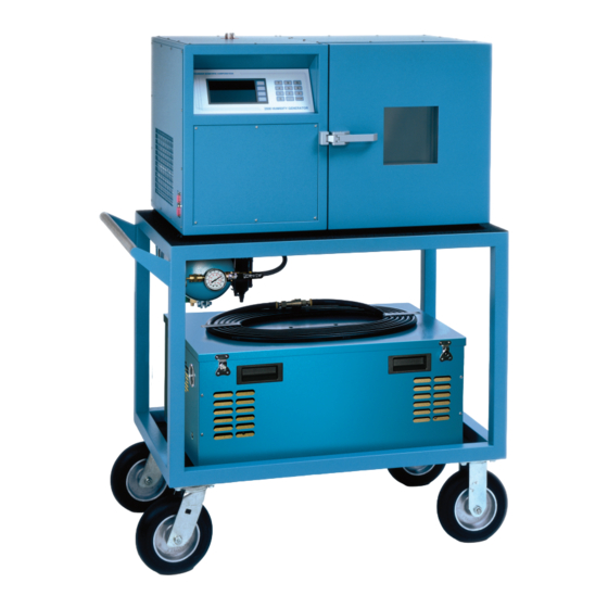
43" (1.09m) wide for 2500ST)(drawing 91D25901). Allow an additional 20" (508mm) in width for clearance, if possible, so as to allow complete opening of the chamber door and access to the test port. RESERVOIR FILL PORT THUNDER SCIENTIFIC COR POR ATION 2500 HUMIDITY GENER ATOR LEFT COMPUTER / PRINTER... -
Page 33: Air Supply (If Used Without Pneumatic Cart)
2.2.3 Air Supply (if used without pneumatic cart) The 2500's pneumatic system requires an air supply that is clean and oil free. If the generator is to be used without the pneumatic cart, instrument air at a maximum pressure of 175 PSIG and capable of a flow rate of at least 20 L/min is recommended. -
Page 34: Positioning And Connections
Remove the air compressor shipping strap. For operation, place the air compressor on the floor and connect the 25 foot (7.62m) air supply hose between the air compressor outlet and the cart air supply inlet. THUNDER SCIENTIFIC COR POR ATION 2500 HUMIDITY GENER ATOR FRONT... -
Page 35: Bench Space
SOUND ENCLOSED COMPRESSOR (Optional) Remove the sound enclosed air compressor shipping strap. For operation, the sound enclosed air compressor may be left on the cart and connected to the cart air supply inlet with the short air hose attached to it or may be set on the floor and connected using the 25 foot (7.62m) air supply hose between the sound enclosed air compressor outlet hose and the cart air supply inlet. -
Page 36: Air Supply
2.3.2.4 Air Supply Using a line size equal to or larger than 1/4" (6.35mm) OD, connect a source of clean, oil free, instrument quality air (refer to 2.2.3) to the 1/4" FPT fitting located at the lower rear of the console (working pressure is 175 PSIG). If the generator is installed on the pneumatic cart, but an alternate air supply (facility) is desired, connect the alternate air supply (175 PSIG MAWP) to the air inlet of the cart air supply so as to utilize the valves, storage tank, filter, and 150 PSIG regulated output of the pneumatic cart (figure 2-5). -
Page 37: Section 3 - Operation
Section 3 OPERATION 3.1 GENERAL At this point, all positioning and preparation of the Series 2500 humidity generator should have been performed. 3.2 STANDARD OPERATING PROCEDURES 3.2.1 Power-Up A) Verify that the air supply connection has been made, that power has been applied to the air compressor, and that the air supply is pressurized. - Page 38 The "SetPnt" column lists control setpoints used as a target value in order to control these parameters. Only those parameters which the generator directly controls have values listed in this column. For instance, since the 2500 has no control over the chamber pressure, that parameter has no value listed in the "SetPnt"...
-
Page 39: Changing The Display Contrast
SATUR °X - The temperature of saturation, Ts, as measured by the saturation fluid temperature probe. Saturation temperature is used in the calculation of %RH @PcTc, and is used to control the temperature of the fluid surrounding the saturator and chamber. Temperatures may be displayed in °C or °F. CHMBR °X - The temperature of the chamber, Tc, as measured by the chamber temperature probe. - Page 40 To change any (or all) of the setpoints, position the cursor over the desired setpoint, then edit the value using the numeric keypad. Continue using the arrow keys and the numeric keypad until all desired values have been changed. End the setpoint editing session by pressing the <ENTER> key on the numeric keypad. The arrow keys revert back to their previously displayed functions, and the setpoints are validated and updated.
-
Page 41: Changing Units
3.2.4 Changing Units The generator can operate in a variety of user selectable pressure, temperature, and flow units. To change units from the main control screen: A) Press the [CHNG UNIT] key. The menu labels change to indicate the currently selected pressure, temperature, and flow units. -
Page 42: Run/Stop
The active control mode setpoint remains constant, while the two inactive mode setpoints vary under computer control with changes in measured temperatures and pressures. Mode 2 (%RH @PcTc) is the most often used and is the power-up default mode of the generator. -
Page 43: Printer (Optional)
Pressing [STOP] causes the computer to perform a system shutdown and consists of the following actions: a) Pressure bleed solenoid valve opens. b) Fluid circulation pump and refrigeration compressor stop. c) Flow and Expansion valves close. d) All control is disabled. Once shutdown is completed the generator is left in an idle mode. -
Page 44: Maintenance Power-Off
3.2.8.1 Maintenance Power-Off Before maintenance of any kind, other than calibration, the following must first be performed: A) Press [STOP], if system is currently RUNNING, to close all valves and disable control. B) Press main rear panel Power switch to OFF. C) Disconnect console from primary power. -
Page 45: Editing System Coefficients And Parameters
3.3 EDITING SYSTEM COEFFICIENTS AND PARAMETERS All of the calibration coefficients and system parameters may be viewed and/or edited by the operator. The following is a summary of items that may be edited. Temperature Probe Calibration Coefficients Pressure Transducer Calibration Coefficients Flow Transducer Calibration Coefficients Probe and Transducer Averaging Serial Port Baud Rates, Parity, etc. - Page 46 An incorrect code prevents access and returns to step 3. A correct code results in the display of calibration coefficients. EDIT NEXT SATURATION TEMP, Ts Zero [-.0851657 Span [ .0200085 PREV [ 4.85408E-09 ] [ 10 DONE Last Cal Date 08/10/12 4.
-
Page 47: Coefficients And Parameters
3.3.2 Coefficients and Parameters Each of the values on the various coefficient and parameter screens will be discussed in detail in the following sections. 3.3.2.1 Temperature Coefficients EDIT NEXT SATURATION TEMP, Ts Zero [-.0851657 Span [ .0200085 PREV [ 4.85408E-09 ] [ 10 DONE Last Cal Date... -
Page 48: Reference Resistor Coefficients
3.3.2.2 Reference Resistor Coefficients These coefficients are similar to the temperature coefficients of section 3.3.2.4. reference resistor is approximately 10KΩ, and the coefficients are chosen to provide a reference value of approximately 0 °C. An AVG amount of approximately 50 is typical. Any change made to either the reference resistor or the coefficients (with the exception of AVG) requires that the temperature calibration of section 4.2.2 be performed on all four probes. -
Page 49: Flow Coefficients
3.3.2.4 Flow Coefficients EDIT NEXT MASS FLOW RATE Zero Span [ 1.6E-3 PREV [ 10 DONE Last Cal Date 08/10/12 The ZERO, SPAN, and LIN values are coefficients to the formula Flow = A + Bx + Cx where A = zero coefficient B = span coefficient C = linearity coefficient x = output of the STD-A/D converter board. -
Page 50: Console Port Parameters
3.3.2.5 Console Port Parameters These parameters affect the manner in which the bi-directional RS-232C Console Port behaves. Changes become effective immediately. EDIT NEXT CONSOLE PORT PARAMETERS Baud [ 2400 Data PREV Stop Parity [ 13 DONE Cancel Baud: 300, 600, 1200, 2400, 4800, 9600, 19200 or 38400 bits per second Data: 7 or 8 bit word size. -
Page 51: Printer Port Parameters
3.3.2.6 Printer Port Parameters These parameters affect the manner in which the unidirectional RS-232 Printer Port behaves. It not only affects communication parameters, but time interval between printouts of system data, and the number of lines to print per page. EDIT NEXT PRINTER PORT PARAMETERS... -
Page 52: Section 4 - Calibration And Maintenance
Section 4 CALIBRATION AND MAINTENANCE 4.1 GENERAL The Series 2500 humidity generation system requires little periodic maintenance. Following the proper operating procedures as given in this manual will help assure trouble-free operation of this system. 4.2 CALIBRATION Proper calibration of the temperature and pressure transducers is critical to the accuracy of the generated humidity. -
Page 53: A/D Board (Std-A/D)
Calibration of all transducers is to be performed "in the system, as a system". There are no provisions for, nor do we recommend, calibration of any of the transducers (temperature, pressure, or flow) while electrically disconnected from the generator. Since all calibration is performed mathematically by the computer, there are no manual adjustments. -
Page 54: Temperature Calibration Procedure
4.2.2.1 Temperature Calibration Procedure Reference Drawing 91D25902 1) Switch main console power OFF. 2) Turn OFF or disconnect the air supply. CAUTION! ALL SYSTEM PRESSURE MUST BE VENTED BEFORE PROCEEDING. 3) Using a #10 Torx driver, remove both top panels and the left rear panel from the generator. - Page 55 7) Press the [EDIT/CAL] key. The Edit/Cal menu appears. EDIT PRNT REPT DONE 8) Press the [CAL] key. The calibration menu appears. TEMP PRES FLOW DONE 9) Press the [TEMP CAL] key. The probe selection screen appears. MARK /CLR Count Deg C _ S atur Tmp PrSat Tmp...
- Page 56 11) Once the desired probes are marked, press [OK]. The LOW, MID, and HIGH temperature reference values appear at the bottom of the screen, and within a few seconds, actual data begins updating in the "Count" and "Deg C" columns. TEMP Count Deg C...
- Page 57 14) Repeat step 13 for both a MID temperature (near 35 °C) and HIGH temperature (near 70 °C). Be sure to use the appropriate [MID TEMP] and [HIGH TEMP] keys. Note: Using the LOW TEMP, MID TEMP, or HIGH TEMP key more than once allows the previous point of each thermistor to be over-written with the most current measured value.
-
Page 58: Pressure Transducer Calibration
4.2.3 Pressure Transducer Calibration Pressure Transducer Calibration is typically performed in a calibration laboratory and requires that the transducers be removed from the pneumatic system of the 2500, but must remain electrically connected. The pressure readings must be precise in order to retain accurate relative humidity calculations. - Page 59 7) Switch console power ON. Wait a few moments for the softkey menu to appear. Allow approximately 30 minutes or more for warm-up of the pressure transducer electronics. 8) Press the [EDIT/CAL] key, then the [CAL] key. The calibration menu appears. TEMP PRES FLOW...
- Page 60 12) Apply the lower recommended calibration pressure and watch the displayed value. Once stable, press the [LOW PRES] key and enter the reference pressure. Then press <ENTER>. Count PSIA OOPS *Low Range 2444 12.18 High Range 12.18 High 12.214 _ Note: For the low range transducer, ambient pressure should be used for the low pressure calibration point.
- Page 61 PRES Count PSIA *Low Range 10021 49.92 PRES High Range 12.16 HIGH PRES High CALC COEF 12.214 29.989 49.904 15) Press the [CALC COEF] key. All coefficients for the marked transducer will be calculated, and those of the low range transducer will appear first on the LCD display. PRNT COEF VIEW...
-
Page 62: Flow Transducer Calibration
4.2.4 Flow Transducer Calibration The flow measurement, while indicated on the screen, is not critical to the accuracy of the generated humidity and is not used in the humidity calculations. Flow calibration accuracy depends upon the requirements of the user. Equipment Required: 1. - Page 63 6) Press [FLOW CAL]. 7) Press [MARK/CLR] to mark the flowmeter (indicated by an asterisk to its left). MARK /CLR Count SLPM * _ M ass Flow EXIT QUIT 8) Press [OK]. Within a few seconds, the measured flow readings begin updating. FLOW Count SLPM...
- Page 64 10) Using the 10 liter data obtained in step 2, calculate the following: 10+ (Reference Indication) - (2500 Indication) Press [MID FLOW] and enter this calculated value. Count SLPM OOPS *Mass Flow 2500 High 10.14 _ 11) Using the 20 liter data obtained in step 3, calculate the following: 20+ (Reference Indication) - (2500 Indication) Press [HIGH FLOW] and enter this calculated value.
-
Page 65: Printing The Calibration Report
These new coefficients appear on the display. PRNT COEF MASS FLOW RATE Zero EXIT Span [ 1.6E-03 QUIT SAVE QUIT 13) To obtain a printout of the new coefficients, press [PRNT COEF]. 14) To save the coefficients to non-volatile memory, press [SAVE QUIT]. To discard these new coefficients and revert to the previous ones, press [EXIT QUIT]. - Page 66 menu. Where and when appropriate, open the file containing the Calibration Report with WordPad. The last character in the file is a small square. Delete this. From the File-Page Setup... menu, set all four margins to one (1) inch. Print the data from within WordPad.
- Page 67 Calibration Report TSC Model 2500 Humidity Generator S/N XXXXXXX Date MM/DD/YY Temperature Zero Span Linearity Cal Date Saturation Temperature 0.00000E+00 1.00000E-02 0.00000E+00 MM/DD/YY Presat Temperature 0.00000E+00 1.00000E-02 0.00000E+00 MM/DD/YY Ex Valve Temperature 0.00000E+00 1.00000E-02 0.00000E+00 MM/DD/YY Chamber Temperature 0.00000E+00 1.00000E-02 0.00000E+00 MM/DD/YY Temp Reference Resistor...
-
Page 68: Routine Maintenance
4.3 ROUTINE MAINTENANCE 4.3.1 Console Intake: Monthly 1) Locate console intake on left side of generating console. 2) Remove any dust and other obstructions. 4.3.2 Chamber Fluid Level: Yearly 1) Remove top right console panel. 2) Locate fluid fill cap on top of console (under black insulating foam). 3) Remove cap and check that the fluid is approximately 1/4"... -
Page 69: Error Codes And Troubleshooting
4.4 ERROR CODES and TROUBLESHOOTING Prior to system start-up, and during humidity generation, the system monitors itself for errors and sources of possible malfunction. When a catastrophic error occurs, the system automatically shuts down, then alerts the operator with a visual flashing message and an audible tone. - Page 70 The following is a list of error codes and a brief description of each. ERROR CODE DESCRIPTION Expansion Valve Not Closing Flow Valve Not Closing No Supply Pressure Reservoir Needs Water Presaturator Water Empty Low Pressure Underrange Low Pressure Overrange High Pressure Underrange High Pressure Overrange Pressure Transducer Failure...
- Page 71 Error 1 - Expansion Valve Not Closing This indicates that while attempting to close the expansion valve, the HOME position limit switch closure was not detected. This could mean that either the valve is not moving properly or the switch is mechanically or electrically malfunctioning. Error 2 - Flow Valve Not Closing This indicates that while attempting to close the flow valve, the HOME position limit switch closure was not detected.
- Page 72 Error 320 - Low Pressure Overrange This indicates that a saturation pressure of greater than 60 PSIA, or equivalent in other pressure units, was measured by the low range pressure transducer. Transducer malfunction (either one or both) is likely. Error 480 - Pressure Transducer Misalignment The low and high range pressure transducer measurements disagree with each other by more than 1 PSIA or equivalent in other pressure units, indicating an alignment problem.
- Page 73 Error 16896 - Saturation Temperature Underrange The indicated saturation temperature is below -10 °C (14 °F). Suspect misalignment or malfunction of the saturation temperature probe. Error 17408 - Presaturation Temperature Underrange The indicated presaturation temperature is below -5 °C (23 °F). Suspect misalignment or malfunction of the presaturator temperature probe.
- Page 74 Error -32256 - Saturation Temperature Overrange The indicated saturation temperature is above 90 °C (194 °F). Suspect misalignment or malfunction of the saturation temperature probe. Error -32768 - Temperature Overrange This error never occurs alone. It may only occur in combination with temperature high/low limits to indicate that the error is a high limit rather than a low limit.
-
Page 75: Complete System Components
Section 5 PARTS LISTS COMPLETE SYSTEM COMPONENTS Find # Qty. Description Part Number Analog Terminal Board ADP7409TB Refrigeration Compressor 100/50 & 115/60Hz COMPR-110V/50HZ Refrigeration Compressor 220v/50Hz COMPR-220V/50HZ CBS1 Circuit Breaker Switch 1-Pole BTPWRSW-R CBS1* Circuit Breaker Switch 2-Pole BTPWRSW-2 Card Cage Assembly D92A25013 6"... - Page 76 Find# Qty Description Part Number Pre-saturator Liquid Level Board Assembly D92A00043 Mother Board Back Plane Assembly D92A25024 MOV1 Metal Oxide Varistor MOV1 PLF1 Power Line Filter for BT F1200BB03 PSAT Pre-Sat/Heat Exchanger D94A25048_01 PSAT***** 1 High Air Flow Pre-Sat D94A25048-HAF Tee, Purge 1/4”...
-
Page 77: Pneumatic Cart
Find# Qty Description Part Number Valve, Thermostatic Expansion NIF-1/2-C Valve, Thermostatic Expansion NIF-1/8-C Valve, Constant Pressure 5” HG-90# EV-104 PNEUMATIC CART Find# Qty. Description Part Number ACS**** Enclosure, Air Compressor System ACS2520-115 or -230 Hose, Air, 12.5" D92A25067 Hose, Air, 14.5" D92A25066_01 AH25 Hose, Air, 25'... - Page 78 CHAMBER EXHAUST PORT AIR SUPPLY INLET (1/4" FTP) 1.9" DIAMETER ACCESS PORT PROPRIETARY NOTICE: This Drawing and Information Contained Within is Proprietary to Thunder Scientific and cannot be Copied or Reproduced without Written Permission TOLERANCES TOLERANCES THIRD ANGLE PROJECTION THIRD ANGLE PROJECTION...
-
Page 79: Rear View
This Drawing and Information Contained Within is Proprietary to Thunder Scienti c and cannot be Copied or Reproduced without Written Permission TOLERANCES TOLERANCES THIRD ANGLE PROJECTION THIRD ANGLE PROJECTION PRODUCTION Thunder Scientific Corporation DESIGNATION ± .015 25-Z-2 623 Wyoming S.E. Albuquerque, NM 87123-3198 ± .010 .XXX... -
Page 80: Top View
Thunder Scientific Corporation PROJECTION DESIGNATION THIS DRAWING AND INFORMATION CONTAINED WITHIN IS PROPRIETARY 623 Wyoming S.E. Albuquerque, NM 87123 25-Z-3 TO THUNDER SCIENTIFIC AND CANNOT BE COPIED OR REPRODUCED WITHOUT WRITTEN PERMISSION Card Cage & Component Layout TOLERANCES LONG 6/1/1991 ±.015... - Page 81 Thunder Scientific Corporation PROJECTION DESIGNATION THIS DRAWING AND INFORMATION CONTAINED WITHIN IS PROPRIETARY 25-Z-4 623 Wyoming S.E. Albuquerque, NM 87123 TO THUNDER SCIENTIFIC AND CANNOT BE COPIED OR REPRODUCED Electrical Sub Panel Layout WITHOUT WRITTEN PERMISSION TOLERANCES LONG 6/1/1991 ±.015...
- Page 82 Thunder Scientific Corporation PROPRIETARY NOTICE THIRD ANGLE PROJECTION THIS DRAWING AND INFORMATION CONTAINED 623 Wyoming S.E. Albuquerque, NM 87123 WITHIN IS PROPRIETARY TO THUNDER SCIENTIFIC AND CANNOT BE COPIED OR REPRODUCED WITHOUT SPECIFIC WRITTEN PERMISSION Terminal Layout TOLERANCES Long 6/1/1991...
- Page 83 Thunder Scientific Corporation PROPRIETARY NOTICE THIRD ANGLE PROJECTION THIS DRAWING AND INFORMATION CONTAINED 623 Wyoming S.E. Albuquerque, NM 87123 WITHIN IS PROPRIETARY TO THUNDER SCIENTIFIC AND CANNOT BE COPIED OR REPRODUCED WITHOUT SPECIFIC WRITTEN PERMISSION AC / DC Power Schematic TOLERANCES Long...
- Page 84 Thunder Scientific Corporation PROPRIETARY NOTICE THIRD ANGLE PROJECTION THIS DRAWING AND INFORMATION CONTAINED 623 Wyoming S.E. Albuquerque, NM 87123 WITHIN IS PROPRIETARY TO THUNDER SCIENTIFIC AND CANNOT BE COPIED OR REPRODUCED WITHOUT SPECIFIC WRITTEN PERMISSION Solid State Relay Module Board TOLERANCES Long...
- Page 85 Thunder Scientific Corporation PROPRIETARY NOTICE THIRD ANGLE PROJECTION THIS DRAWING AND INFORMATION CONTAINED 623 Wyoming S.E. Albuquerque, NM 87123 WITHIN IS PROPRIETARY TO THUNDER SCIENTIFIC AND CANNOT BE COPIED OR REPRODUCED WITHOUT SPECIFIC WRITTEN PERMISSION Compressor / Heater Schematic TOLERANCES Long...
- Page 86 Thunder Scientific Corporation PROPRIETARY NOTICE THIRD ANGLE PROJECTION THIS DRAWING AND INFORMATION CONTAINED 623 Wyoming S.E. Albuquerque, NM 87123 WITHIN IS PROPRIETARY TO THUNDER SCIENTIFIC AND CANNOT BE COPIED OR REPRODUCED WITHOUT SPECIFIC WRITTEN PERMISSION Liquid Level / Speaker Schematic TOLERANCES Long...
- Page 87 Thunder Scientific Corporation PROPRIETARY NOTICE THIRD ANGLE PROJECTION THIS DRAWING AND INFORMATION CONTAINED 623 Wyoming S.E. Albuquerque, NM 87123 WITHIN IS PROPRIETARY TO THUNDER SCIENTIFIC AND CANNOT BE COPIED OR REPRODUCED WITHOUT SPECIFIC WRITTEN PERMISSION Flow Valve (V1) Control Schematic TOLERANCES Long...
- Page 88 Thunder Scientific Corporation PROPRIETARY NOTICE THIRD ANGLE PROJECTION THIS DRAWING AND INFORMATION CONTAINED 623 Wyoming S.E. Albuquerque, NM 87123 WITHIN IS PROPRIETARY TO THUNDER SCIENTIFIC AND CANNOT BE COPIED OR REPRODUCED WITHOUT SPECIFIC WRITTEN PERMISSION Exp. Valve (V2) Control Schematic TOLERANCES Long...
- Page 89 Thunder Scientific Corporation PROPRIETARY NOTICE THIRD ANGLE PROJECTION THIS DRAWING AND INFORMATION CONTAINED 623 Wyoming S.E. Albuquerque, NM 87123 WITHIN IS PROPRIETARY TO THUNDER SCIENTIFIC AND CANNOT BE COPIED OR REPRODUCED WITHOUT SPECIFIC WRITTEN PERMISSION Temp Probe / Transducer Schematic TOLERANCES Long...
- Page 90 Thunder Scientific Corporation PROPRIETARY NOTICE THIRD ANGLE PROJECTION THIS DRAWING AND INFORMATION CONTAINED 623 Wyoming S.E. Albuquerque, NM 87123 WITHIN IS PROPRIETARY TO THUNDER SCIENTIFIC AND CANNOT BE COPIED OR REPRODUCED WITHOUT SPECIFIC WRITTEN PERMISSION STD Bus Diagram TOLERANCES Long...
- Page 91 Thunder Scientific Corporation PROPRIETARY NOTICE THIRD ANGLE PROJECTION THIS DRAWING AND INFORMATION CONTAINED 623 Wyoming S.E. Albuquerque, NM 87123 WITHIN IS PROPRIETARY TO THUNDER SCIENTIFIC AND CANNOT BE COPIED OR REPRODUCED WITHOUT SPECIFIC WRITTEN PERMISSION Display Block Diagram TOLERANCES Long...
- Page 92 HAND CORNER OF THE PROJECTION THIS DRAWING AND INFORMATION CONTAINED LEFT SIDE PANEL 623 Wyoming S.E. Albuquerque, NM 87123 WITHIN IS PROPRIETARY TO THUNDER SCIENTIFIC AND CANNOT BE COPIED OR REPRODUCED WITHOUT SPECIFIC WRITTEN PERMISSION RS-232C / Printer Console TOLERANCES...
- Page 93 THIRD ANGLE Thunder Scientific Corporation PROJECTION DESIGNATION THIS DRAWING AND INFORMATION CONTAINED WITHIN IS PROPRIETARY 25-Z-16 623 Wyoming S.E. Albuquerque, NM 87123 TO THUNDER SCIENTIFIC AND CANNOT BE COPIED OR REPRODUCED Pneumatic System Schematic WITHOUT WRITTEN PERMISSION TOLERANCES LONG 6/1/1991 ±.015...
- Page 94 Thunder Scientific Corporation PROPRIETARY NOTICE THIRD ANGLE PROJECTION THIS DRAWING AND INFORMATION CONTAINED 623 Wyoming S.E. Albuquerque, NM 87123 WITHIN IS PROPRIETARY TO THUNDER SCIENTIFIC AND CANNOT BE COPIED OR REPRODUCED WITHOUT SPECIFIC WRITTEN PERMISSION Heat Transfer Fluid Schematic TOLERANCES Long...
- Page 95 Thunder Scientific Corporation PROPRIETARY NOTICE THIRD ANGLE PROJECTION THIS DRAWING AND INFORMATION CONTAINED 623 Wyoming S.E. Albuquerque, NM 87123 WITHIN IS PROPRIETARY TO THUNDER SCIENTIFIC AND CANNOT BE COPIED OR REPRODUCED WITHOUT SPECIFIC WRITTEN PERMISSION Refrigeration System Schematic TOLERANCES Long...
- Page 96 THIRD ANGLE PROJECTION THIS DRAWING AND INFORMATION CONTAINED MODEL 623 Wyoming S.E. Albuquerque, NM 87123 WITHIN IS PROPRIETARY TO THUNDER SCIENTIFIC AND CANNOT BE COPIED OR REPRODUCED WITHOUT 2500 40.00" 23.00" 24.00" 33.25" SPECIFIC WRITTEN PERMISSION ACS with Cart Layout 1.02M 584mm 609mm 845mm...
- Page 97 PRODUCTION THIRD ANGLE PROJECTION DESIGNATION THIS DRAWING AND INFORMATION CONTAINED WITHIN IS PROPRIETARY 623 Wyoming S.E. Albuquerque, NM 87123 25-Z-21 TO THUNDER SCIENTIFIC AND CANNOT BE COPIED OR REPRODUCED Cart Pneumatic System Schematic WITHOUT WRITTEN PERMISSION TOLERANCES LONG 6/1/1991 ±.015...
- Page 98 (4 U.S. gallons for 2500ST) fill until level is approximately 25-Z-24 623 Wyoming S.E. Albuquerque, NM 87123 TO THUNDER SCIENTIFIC AND 1/4" below bottom of fill port, or to bottom of funnel. CANNOT BE COPIED OR REPRODUCED Remove funnel and replace fluid fill port cap and insulation.
- Page 99 SIDE VIEW Thunder Scientific Corporation PROPRIETARY NOTICE THIRD ANGLE DIMENSIONS PROJECTION THIS DRAWING AND INFORMATION CONTAINED 623 Wyoming S.E. Albuquerque, NM 87123 WITHIN IS PROPRIETARY TO THUNDER SCIENTIFIC MODEL AND CANNOT BE COPIED OR REPRODUCED WITHOUT 2500 40.00" 23.00" 24.00" 33.25"...
- Page 100 Thunder Scientific Corporation PROPRIETARY NOTICE THIRD ANGLE PROJECTION THIS DRAWING AND INFORMATION CONTAINED 623 Wyoming S.E. Albuquerque, NM 87123 WITHIN IS PROPRIETARY TO THUNDER SCIENTIFIC AND CANNOT BE COPIED OR REPRODUCED WITHOUT SPECIFIC WRITTEN PERMISSION 2500 Fuse Upgrade Schematic TOLERANCES Furry...
-
Page 101: Low Voltage
Thunder Scientific Corporation PROPRIETARY NOTICE THIRD ANGLE PROJECTION THIS DRAWING AND INFORMATION CONTAINED 623 Wyoming S.E. Albuquerque, NM 87123 WITHIN IS PROPRIETARY TO THUNDER SCIENTIFIC AND CANNOT BE COPIED OR REPRODUCED WITHOUT SPECIFIC WRITTEN PERMISSION ACS Twin Electrical Schematic TOLERANCES Furry... - Page 102 Thunder Scientific Corporation PROPRIETARY NOTICE THIRD ANGLE PROJECTION THIS DRAWING AND INFORMATION CONTAINED 623 Wyoming S.E. Albuquerque, NM 87123 WITHIN IS PROPRIETARY TO THUNDER SCIENTIFIC AND CANNOT BE COPIED OR REPRODUCED WITHOUT SOECIFIC WRITTEN PERMISSION ACS Twin Electrical Schematic TOLERANCES FURRY...
- Page 103 Read Actual Values Description Returns the current generated system values. Prerequisites Requires Benchtop firmware revision 1.05 or greater. Syntax Parameters None Remarks Data Returned returns a list of 8 comma separated values indicating the current data and status of the system. These values are returned in the same order as they appear on the Benchtop screen and always in the units listed below.
- Page 104 Read Setpoints Description Returns the current system Setpoints and operating mode. Prerequisites Requires Benchtop firmware revision 1.05 or greater. Syntax Parameters None Remarks Data Returned returns a list of 6 comma separated values indicating the current setpoints and operating mode of the system. These values are returned in the same order as they appear on the Benchtop screen and always in the units listed below.
- Page 105 ?RUN Read Run Status Description Returns the current system operating status. Prerequisites Requires Benchtop firmware revision 1.05 or greater. Syntax ?RUN Parameters None Remarks Data Returned returns one of two values to indicate whether or not the system is currently generating (running). The 2 possible returned values are as follows: VALUE DESCRIPTION...
- Page 106 Read Error Number Description Returns the current error number relating to system shutdown. Prerequisites Requires Benchtop firmware revision 1.05 or greater. Syntax Parameters None Remarks Data Returned returns one of several values indicating the reason(s) that the system shut down. The value returned can be any one, or an algebraic combination, of several of the following: VALUE DESCRIPTION...
- Page 107 Cabinet Fan Temperature Description Returns the cabinet fan temperature in °C. Prerequisites Requires Benchtop firmware revision 1.05 or greater. Syntax Parameters None Remarks Data Returned returns the value (in whole °C only) of the cabinet fan temperature. Examples command is used to read the current cabinet temperature. computer sends <CR>...
- Page 108 Start the System Description Starts the system just as if the front panel "RUN" key had been pressed. Prerequisites None. Syntax Parameters None Remarks Data Returned None. The only response is a carriage return/linefeed terminator. Examples command is used to start the system. computer sends <CR>...
- Page 109 STOP Stop the System Description Stops the system just as if the front panel "STOP" key had been pressed. Prerequisites None. Syntax STOP Parameters None Remarks Data Returned None. The only response is a carriage return/linefeed terminator. Examples command is used to stop a running system. STOP STOP computer sends...
- Page 110 PRINT Print System Data Description Sends one line of data, in the units currently displayed on the control screen, to a printer, if connected to the Benchtop's printer port, just as if the front panel <•> key had been pressed. Prerequisites The system must be running, and the serial port parameters must match between the Benchtop and the printer used.
- Page 111 Change RH @Pc Setpoint Description Changes the RH @Pc setpoint to a given value. Prerequisites Requires Benchtop firmware revision 1.05 or greater. Syntax R1=setpoint Parameters The setpoint value is the %RH that the system should generate. setpoint Remarks Control Mode Changed Sending setpoint also changes the control mode to %RH @Pc (mode 1).
- Page 112 Change RH @PcTc Setpoint Description Changes the RH @PcTc setpoint to a given value. Prerequisites Requires Benchtop firmware revision 1.05 or greater. Syntax R2=setpoint Parameters The setpoint value is the %RH that the system should generate. setpoint Remarks Control Mode Changed Sending setpoint also changes the control mode to %RH @PcTc (mode 2).
- Page 113 Change Saturation Pressure Setpoint Description Changes the Saturation Pressure setpoint to a given value. Prerequisites Requires Benchtop firmware revision 1.05 or greater. Syntax PS=setpoint Parameters The setpoint value is the Saturation Pressure, in psia only, that the setpoint system should control at. Remarks Control Mode Changed Sending...
- Page 114 Change Saturation Temp Setpoint Description Changes the Saturation Temperature setpoint to a given value. Prerequisites Requires Benchtop firmware revision 1.05 or greater. Syntax TS=setpoint Parameters The setpoint value is the Saturation Temperature, in °C only, that the setpoint system should control at. Remarks Precautions Chamber temperature follows Saturation Temperature.
- Page 115 Change Flow Rate Setpoint Description Changes the Flow Rate setpoint to a given value. Prerequisites Requires Benchtop firmware revision 1.05 or greater. Syntax FS=setpoint Parameters The setpoint value is the Flow rate, in L/min only, that the system setpoint should control at. Remarks Data Returned None.
- Page 116 System Authorization Code: 2500 This code was designed to prevent unauthorized personnel access to the calibration coefficients.
- Page 117 THUNDER SCIENTIFIC CORPORATION ® 623 Wyoming Blvd. SE Albuquerque NM 87123-3198 www.thunderscientific.com...
Need help?
Do you have a question about the 2500 series and is the answer not in the manual?
Questions and answers