ABB REM 610 Product Manual
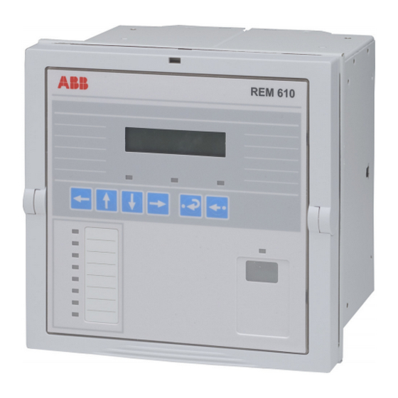
Motor protection relay
Hide thumbs
Also See for REM 610:
- Technical reference manual (158 pages) ,
- Operator's manual (68 pages) ,
- Product manual (36 pages)
Table of Contents
Advertisement
Quick Links
Advertisement
Table of Contents

Subscribe to Our Youtube Channel
Related Manuals for ABB REM 610


Summary of Contents for ABB REM 610
- Page 1 Motor Protection Relay REM 610 Product Guide...
-
Page 3: Motor Protection Relay
Motor Protection Relay REM 610 1MRS 755121 Issued: 01.12.2003 Status: Updated Version: D/28.11.2006 Data subject to change without notice Features • Three-phase motor start-up supervision • Two galvanically isolated digital inputs and based on thermal stress calculation with three additional galvanically isolated digital... -
Page 4: Protection Functions
It handles fault conditions during REM 610 can equally well be used to protect, motor start up, normal run, idling, and cool- for instance, feeder cables and power trans- ing down at standstill, e.g. - Page 5 Motor Protection Relay REM 610 1MRS 755121 Settings Before the relay is connected to a system it The setting values can be altered via the HMI must be assured that the relay has been given or with a PC provided with the Relay Setting the correct settings, see table 2 below.
-
Page 6: Technical Data
Motor Protection Relay REM 610 1MRS 755121 Technical data Table 3: Dimensions Width frame 177 mm, case 164 mm Height frame 177 mm (4U), case 160 mm Depth case 149.3 mm Weight of the relay ~3.5 kg Weight of the spare unit ~1.8 kg... - Page 7 Motor Protection Relay REM 610 1MRS 755121 Technical data (cont´d) Table 6: Measuring range Measured currents on phases I and I as multiples of 0...50 x I the rated currents of the energizing inputs Earth-fault current as a multiple of the rated current of the 0...8 x I...
- Page 8 Motor Protection Relay REM 610 1MRS 755121 Technical data (cont´d) Table 12: RTD/analogue inputs 100 Ω platinum Supported RTD sensors TCR0.00385 (DIN 43760) 250 Ω platinum TCR 0.00385 1000 Ω platinum TCR 0.00385 100 Ω nickel TCR 0.00618 (DIN 43760) 120 Ω...
- Page 9 Motor Protection Relay REM 610 1MRS 755121 Technical data (cont´d) Table 14: Electromagnetic compatibility tests Surge immunity test: According to the IEC 61000-4-5 • Power outputs, energizing inputs, power supply 4 kV, line-to-earth 2 kV, line-to-line • I/O ports 2 kV, line-to-earth...
-
Page 10: Connection Diagrams
Motor Protection Relay REM 610 1MRS 755121 Connection dia- grams Fig. 2 Residual current is measured via a core-balanced current transformer. - Page 11 Motor Protection Relay REM 610 1MRS 755121 Connection diagrams (cont´d) Fig. 3 Residual current is measured via a summation connection of the phase current transformers.
- Page 12 Motor Protection Relay REM 610 1MRS 755121 Connection diagrams (cont´d) Fig. 4 REM 610 connected to a contactor controlled motor with the trips routed to trip the contactor.
-
Page 13: Ordering Information
Motor Protection Relay REM 610 1MRS 755121 Ordering informa- When ordering REM 610 protection relays The order number identifies the protection tion and/or accessories, please specify the follow- relay type and hardware as described in fig- ing: ures below and is labelled on the marking strip under the lower handle of the relay. - Page 14 Configuration, setting and SA system tools: The following tool versions are needed to support the new functions and features of REM 610 release C: CAP 501 Relay Setting Tool CAP 501 v. 2.4.0-1 or later CAP 505 Relay Setting Tool CAP 505 v.
- Page 16 ABB Oy Distribution Automation P.O. Box 699 FI-65101 Vaasa, FINLAND Tel +358 10 22 11 Fax +358 10 224 1094 www.abb.com/substationautomation...
Need help?
Do you have a question about the REM 610 and is the answer not in the manual?
Questions and answers