Advertisement
Quick Links
BE SURE POWER IS DISCONNECTED PRIOR TO INSALLATION!
FOLLOW NATIONAL, STATE, AND LOCAL CODES!
READ THESE INSTRUCTIONS ENTIRELY BEFORE INSTALLATION!
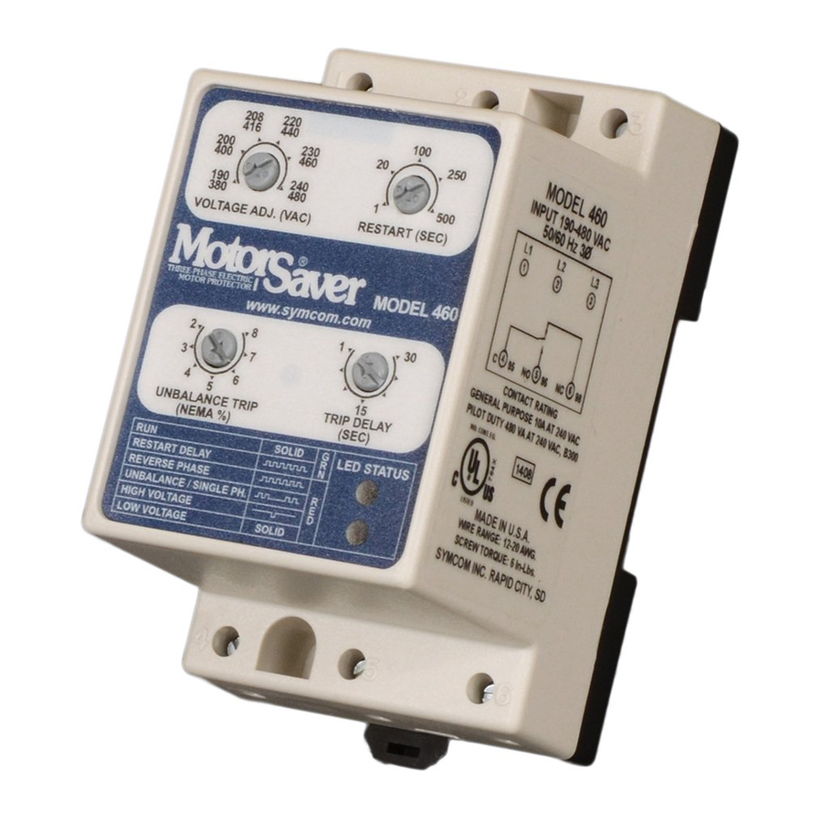
The Model 460 MotorSaver
protect three-phase motors regardless of size. The MotorSaver
190-480 VAC, 50 to 60 Hz motors to protect from damage caused by single
phasing, low voltage, high voltage, phase reversal, and voltage unbalance.
CONNECTIONS
1. Mount the MotorSaver
control panel. If the location is wet or dusty, the MotorSaver
be mounted in a NEMA 4 or 12 enclosure. The MotorSaver
mounted to a back panel using two #6 or #8 x 5/8 screws or can be
snapped onto a DIN rail.
2. Connect L1, L2 and L3 on the MotorSaver's terminal strip to the LINE SIDE
of the motor starter. (See Figure No. 1).
3. Connect the output relay to the circuitry to be controlled. For motor control,
connect the normally open contact in series with the magnetic coil of the
motor starter as shown in Figure No. 1. For alarm operation, connect the
normally closed contact in series with the control circuit as shown in Figure
No. 2.
INSTALLATION INSTRUCTIONS
FOR SYMCOM'S MOTORSAVER
is an auto ranging voltage monitor designed to
in a convenient location in or near the motor
MODEL 460
is used on
should
can be
Advertisement

Related Manuals for SymCom MOTORSAVER 460


Summary of Contents for SymCom MOTORSAVER 460
- Page 1 INSTALLATION INSTRUCTIONS FOR SYMCOM’S MOTORSAVER MODEL 460 BE SURE POWER IS DISCONNECTED PRIOR TO INSALLATION! FOLLOW NATIONAL, STATE, AND LOCAL CODES! READ THESE INSTRUCTIONS ENTIRELY BEFORE INSTALLATION! The Model 460 MotorSaver is an auto ranging voltage monitor designed to ...
- Page 2 CONTROL VOLTAGE 24-240 VAC FIGURE NO. 1: CONTROL WIRING DIAGRAM CONTROL VOLTAGE LIGHT 24-240 VAC FIGURE NO. 2: ALARM WIRING DIAGRAM Phone: 800.894.0412 - Fax: 888.723.4773 - Web: www.clrwtr.com - Email: info@clrwtr.com...
- Page 3 1% voltage unbalance without derating derating the motor. The NEMA MG1 standard also recommends against operating a motor above a 5% voltage unbalance under any circumstances. SymCom recommends consulting the motor manufacturer for specifi c tolerances. Maximum Deviation from the Average x 100...
- Page 4 POWER-UP Turn on the 3∅ power to the motor. The MotorSaver’s green RUN light will blink during the RESTART delay. After the RESTART delay, the MotorSaver during the RESTART delay. After the RESTART delay, the MotorSaver during the RESTART delay. After the RESTART delay, the MotorSaver will ®...
-
Page 5: Troubleshooting
N / A to operate its internal electronics. This completely dead. may occur on a single-phased system. If the voltages are correct, call SymCom at 1-800-843-8848 or 1-605-348-5580. Turn off the three-phase power. Swap any Red light is two leads powering the MotorSaver (L1, ... -
Page 6: Specifications
SPECIFICATIONS 3 - Phase Line Voltage 190 - 480 VAC Frequency 50* - 60 Hz Low Voltage (% of setpoint) Trip 90% ± 1% Reset 93% ± 1% High Voltage (% of setpoint) Trip 110% ±1% Reset 107% ±1% Voltage Unbalance (NEMA) Trip 2 - 8% Adjustable Trip Setting minus 1% (5 - 8%) - Page 7 (5) years* from the date of manufacture. All other products manufactured by SymCom shall be warranted against defects in material and workmanship for a period of two (2) years from the date of manufacture. For complete information on warranty, liability, terms, and conditions, please refer to the SymCom Terms and Conditions of Sale document.
Need help?
Do you have a question about the MOTORSAVER 460 and is the answer not in the manual?
Questions and answers