Table of Contents
Advertisement
Advertisement
Table of Contents

Subscribe to Our Youtube Channel
Related Manuals for Staubli 90B family

Summary of Contents for Staubli 90B family
- Page 1 Arm - RX series 90B family Characteristics D18326204C - 11/2004...
- Page 2 The specifications contained in the present document can be modified without notice. Although all necessary precautions have been taken to ensure that the information contained in this document is correct, STÄUBLI cannot be held responsible for any errors or omissions found in the illustrations, drawings and specifications contained in the said document.
-
Page 3: Table Of Contents
TABLE OF CONTENTS 1 - DESCRIPTION ..................7 1.1. GENERAL PRESENTATION ....................9 1.2. DESIGNATION OF ROBOTS OF THE RX SERIES 90B FAMILY ......... 11 1.3. GENERAL CHARACTERISTICS.................... 11 1.3.1. Overall dimensions...................... 11 1.3.2. Work environment ....................... 11 1.3.3. Weight ......................... 11 1.4. - Page 4 D18326204C - 11/2004...
- Page 5 3 - INSTALLATION ................... 35 3.1. ARM PACKAGING ......................... 37 3.2. HANDLING OF PACKING ...................... 37 3.3. UNPACKING AND INSTALLATION OF ARM ............... 37 3.4. INSTALLATION OF ARM ....................... 39 3.4.1. Installation of arm on floor ................... 39 3.4.2. Installation of arm on ceiling..................39 3.4.3.
- Page 6 D18326204C - 11/2004...
-
Page 7: Description
Chapter 1 – Description CHAPTER 1 – DESCRIPTION D18326204C - 11/2004... - Page 8 Figure 1.1 D18326204C - 11/2004...
-
Page 9: General Presentation
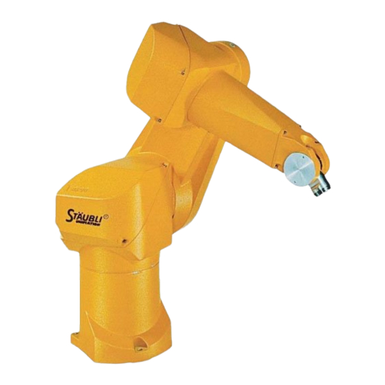
Chapter 1 – Description 1.1. GENERAL PRESENTATION The arm consists of segments or members interconnected by joints (figure 1.1). Each joint comprises an axis around which two members pivot. The movements of the robot’s joints are generated by brushless motors coupled to resolvers. Each of these motors is equipped with a parking break. - Page 10 Figure 1.2 Figure 1.3 D18326204C - 11/2004...
-
Page 11: Designation Of Robots Of The Rx Series 90B Family
Chapter 1 – Description 1.2. DESIGNATION OF ROBOTS OF THE RX SERIES 90B FAMILY RX family arm Maximum reach between joints 2 and 5 expressed in decimeters: dimension + dimension Number of active joints: • 0 = 6 active joints. - Page 12 Figure 1.4 D18326204C - 11/2004...
-
Page 13: Performance
Chapter 1 – Description 1.4. PERFORMANCE See figure 1.4 Brake release access area Area accessible in righty configuration STANDARD ARM LONG ARM Work envelope R.M max. reach between joints 2 and 5 900 mm 1100 mm R.m min. reach between joints 2 and 5 289 mm 401 mm R.b reach between joints 3 and 5... - Page 14 Figure 1.5 D18326204C - 11/2004...
-
Page 15: Load Capacity - Mechanical Interface
Chapter 1 – Description 1.5. LOAD CAPACITY – MECHANICAL INTERFACE Mechanical interface End-effector The end-effector is not supplied with the robot arm assembly; its design depends on the robot’s specific applications. All studies can be undertaken in cooperation with STÄUBLI to obtain optimum performance without exceeding the robot arm assembly load limits. - Page 16 Effective tapped depth : 8 mm Figure 1.6 D18326204C - 11/2004...
-
Page 17: Attachment Of Additional Load On Forearm
Chapter 1 – Description 1.5.2. ATTACHMENT OF ADDITIONAL LOAD ON FOREARM An additional load can be attached to the forearm using 4 M5 screws; maximum torque is 7 Nm. Position of 4 M5 tapped holes: See figure 1.6. DIMENSIONS STANDARD ARM LONG ARM 167.5 ±... - Page 18 Figure 1.7 Figure 1.8 Figure 1.9 Figure 1.10 D18326204C - 11/2004...
-
Page 19: Additional Load Diagrams
Chapter 1 – Description 1.5.3. ADDITIONAL LOAD DIAGRAMS These diagrams can be used to determine the additional load which can be attached to the forearm depending on its center of gravity position from joint 3 and the load attached to the mechanical interface of the wrist. - Page 20 Figure 1.11 Figure 1.12 D18326204C - 11/2004...
-
Page 21: User Circuit
Chapter 1 – Description 1.6. USER CIRCUIT The electric wiring of the arm is assembled into a harness including several cables supplying the motors (power, brakes, resolvers), the solenoid valves, the limit switches and user connector. These components are connected by means of removable connectors. The harness also includes pneumatic hoses which supply air to the solenoid valves (EV1 and EV2). - Page 22 Figure 1.13 D18326204C - 11/2004...
-
Page 23: Pneumatic And Electric Circuits (Except For Clean Room Application)
Chapter 1 – Description 1.8. PNEUMATIC AND ELECTRIC CIRCUITS (EXCEPT FOR CLEAN ROOM APPLICATION) 1.8.1. PNEUMATIC CIRCUIT Plate attached to base Forearm Solenoid valves (EV1 and EV2): • 5/2-way monostable. • Electrically controlled (24 VDC). • Working pressure: 1.5 to 7 bar. •... - Page 24 Figure 1.14 D18326204C - 11/2004...
-
Page 25: Pneumatic And Electric Circuits Clean Room Application
Chapter 1 – Description 1.9. PNEUMATIC AND ELECTRIC CIRCUITS CLEAN ROOM APPLICATION 1.9.1. PNEUMATIC CIRCUIT Plate attached to base Forearm Solenoid valves (EV1 and EV2): • 5/2-way monostable. • Electrically controlled (24 VDC). • Max. working pressure: vacuum only. • Flow coefficient KV 5.72. •... - Page 26 Figure 1.15 Figure 1.16 D18326204C - 11/2004...
-
Page 27: Pressurization Unit For Dusty Environments
Chapter 1 – Description 1.10. PRESSURIZATION UNIT FOR DUSTY ENVIRONMENTS 1.10.1. PURPOSE For very severe applications in dusty environment, to maintain the inside of the arm at a pressure greater than the atmospheric pressure to avoid migration of dust. 1.10.2. INSTALLATION •... - Page 28 FLOOR CONFIGURATION CEILING CONFIGURATION 1) Balanced position (joint 2 brake released) is as follows: without load: with nominal load: without load: with nominal load: A = 90 A = 90˚ A = 180 A = 180˚ ˚ A = 90 A = 90˚...
-
Page 29: Safety
Chapter 1 – Description 1.11. SAFETY The robot arm’s energy is that accumulated by the springs. Indeed, joint 2 is equipped with a spring balance system. Releasing joint 2 discharges the accumulated energy. This energy label is attached on the arm and must remain in place. The brake release movements are described on the opposite page according to arm configuration (floor or ceiling). - Page 30 D18326204C - 11/2004...
-
Page 31: On-Site Preparation
Chapter 2 – On-site preparation CHAPTER 2 – ON-SITE PREPARATION D18326204C - 11/2004... - Page 32 Figure 2.1 D18326204C - 11/2004...
-
Page 33: Working Space
Chapter 2 – On-site preparation 2.1. WORKING SPACE The user is responsible for performing all preparatory work required to complete the on-site installation of the robot. Working space must be sufficient, installation surface appropriate; power sources shall be available (for electrical power, consult controller characteristics). DANGER: The arm's working area must be surrounded by a closed safety enclosure in compliance with the country's safety legislation preventing personnel... - Page 34 D18326204C - 11/2004...
-
Page 35: Installation
Chapter 3 – Installation CHAPTER 3 – INSTALLATION D18326204C - 11/2004... - Page 36 Figure 3.1 Figure 3.2 Figure 3.3 D18326204C - 11/2004...
-
Page 37: Arm Packaging
Chapter 3 – Installation 3.1. ARM PACKAGING (figure 3.1) Standard packaging: Case (1): L x H x P = 850 x 1210 x 640 mm Gross weight: • Standard arm:136 kg • Long arm:137 kg International packaging: Case (1): L x H x P = 935 x 1210 x 670 mm Gross weight: •... - Page 38 Figure 3.4 Figure 3.5 Figure 3.6 Figure 3.7 D18326204C - 11/2004...
-
Page 39: Installation Of Arm
Chapter 3 – Installation 3.4. INSTALLATION OF ARM CAUTION: The arm can be attached with the base downwards (floor-mounted version) or with base upwards (ceiling-mounted version). Caution: the balance system is installed in the factory for one OR the other of these versions. Conversion from a floor-mounted version to a ceiling-mounted version requires a mechanical operation on the balance system. - Page 40 ceiling 90˚ floor Figure 3.8 Figure 3.10 Figure 3.9 Figure 3.12 Figure 3.11 D18326204C - 11/2004...
-
Page 41: Spring Tension
Chapter 3 – Installation 3.5. SPRING TENSION CAUTION: The robot must be attached to the ceiling. Do not rotate joint 2. Figure 3.9 • Remove hoisting ring (9) from the arm. • Unscrew the 4 M5 screws (1) attaching cover (2). •... - Page 42 D18326204C - 11/2004...
Need help?
Do you have a question about the 90B family and is the answer not in the manual?
Questions and answers