Table of Contents
Advertisement
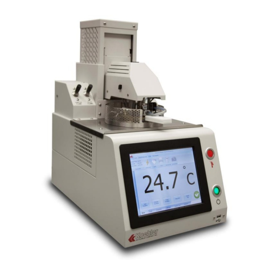
K71000
Automatic PMCC Flash Point Analyzer
Operation and Instruction Manual
REV A
Koehler Instrument Company, Inc.
1595 Sycamore Avenue • Bohemia, New York 11716-1796 • USA
Toll Free: 1-800-878-9070 (US only) • Tel: +1 631 589 3800 • Fax: +1 631 589 3815
http://www.koehlerinstrument.com • e-mail: info@koehlerinstrument.com
Petroleum Testing & Analysis Instrumentation • Custom Design & Manufacturing
Advertisement
Table of Contents

Subscribe to Our Youtube Channel
Related Manuals for Koehler K71000


Summary of Contents for Koehler K71000
- Page 1 Automatic PMCC Flash Point Analyzer Operation and Instruction Manual REV A Koehler Instrument Company, Inc. 1595 Sycamore Avenue • Bohemia, New York 11716-1796 • USA Toll Free: 1-800-878-9070 (US only) • Tel: +1 631 589 3800 • Fax: +1 631 589 3815 http://www.koehlerinstrument.com •...
- Page 3 Responsibility for Registration and Annual Reporting: Koehler will not sell directly to end users in the EU and so has no responsibility to register within each EU state and to make annual reports. Koehler declares that this responsibility is born by the importer who is the first level of the distribution chain and is subject to producer responsibility.
- Page 4 K71000 Automatic PMCC Flash Point Analyzer Operation and Instruction Manual this. All Koehler equipment has been placed on the market since 13th August 2005 and so Koehler is defined as a "new WEEE producer". As such we must provide information on refurbishment, treatment, and re-use.
-
Page 5: Table Of Contents
Intellectual Property ......................4 Liability ..........................4 1 Introduction ........................5 1.1 Koehler's Commitment to Our Customers ..................... 5 1.2 Recommended Resources and Publications ..................5 1.3 Pensky-Martens Flash Point Method Scope and Summary ..............6 1.4 Instrument Specifications ........................7 2 Safety Information and Warnings ................. -
Page 6: Intellectual Property
Koehler Instrument Co. assumes no liability for losses arising from the negligent or improper use of our equipment nor for losses arising from the improper use or use other than intended. Only deliberate action or gross negligence are grounds for any claim. -
Page 7: Introduction
IP 34: Determination of closed flash point with the best solutions. You can depend on – Pensky-Martens method Koehler for a full range of accurate and reliable instrumentation as well as support for your 4. Deutsche International Norm (DIN) laboratory testing programs. Please do not http://www.din.de... -
Page 8: Pensky-Martens Flash Point Method Scope And Summary
K71000 Automatic PMCC Flash Point Analyzer Operation and Instruction Manual DIN EN 22719: Petroleum products and Pensky-Martens Flash Point Method Scope and Summary lubricants; determination of flash point; Pensky-Martens closed method The K71000 Automatic Pensky-Martens Flash (withdrawn) Point Analyzer determines the lowest flash point temperature of fuels, lubricating oils, and 5. -
Page 9: Instrument Specifications
K71000 Automatic PMCC Flash Point Analyzer Operation and Instruction Manual Once analysis is complete the results are Cleaning: Cover / Motor assembly displayed to the screen and saved to the lift features convenient instrument hard disk drive. The results may be cleaning position. -
Page 10: Safety Information And Warnings
K71000 Automatic PMCC Flash Point Analyzer Operation and Instruction Manual Temperature 2 Safety Information and Warnings Calibration: Three (3) Types Safety Considerations available: - 2 Point Sample The most important safety consideration is that Temperature (Standard) people are operating this piece of equipment. -
Page 11: Contaminated Samples
O.E.M. exact replacement equipment. Safe Quick Test Method Chemical Reagents Information The K71000 has a quick test option that begins testing at ambient then heats the sample at an Chemicals and reagents used in performing the accelerated pace while applying the igniter at test may exhibit potential hazards. -
Page 12: Other Important Hazards
K71000 Automatic PMCC Flash Point Analyzer Operation and Instruction Manual any fumes that may be emitted during the test. alterations to this equipment are allowed; doing Conduct tests behind a safety shield, especially so may void the warranty. if you are not sure of the flash point or the ignition temperature. -
Page 13: Unpacking
Certified Reference Material adjustments to the feet located at the base of the unit. Please note that Koehler does not Unpacking supply a level with this equipment. 1. Check Shock Watch Label on Cardboard... - Page 14 K71000 Automatic PMCC Flash Point Analyzer Operation and Instruction Manual Distilled fuel must be wiped off of instrument work surfaces and not be allowed to collect. WARNING: For safety, disconnect the This is a flammability hazard and collects power when performing any maintenance and/or dust.
-
Page 15: Descriptions
K71000 Automatic PMCC Flash Point Analyzer Operation and Instruction Manual 4 Descriptions Front of Instrument Figure 1: Instrument Descriptions_Front -13- K71000-Manual... - Page 16 K71000 Automatic PMCC Flash Point Analyzer Operation and Instruction Manual 1. Power Button: This button allows the user to turn the instrument on and off from the front side. The main power switch at the back of the unit (Figure 2, Item 12) must be switched ON prior to pressing on the power button.
-
Page 17: Back Of Instrument
K71000 Automatic PMCC Flash Point Analyzer Operation and Instruction Manual Back of Instrument Figure 2: Instrument Descriptions_Back -15- K71000-Manual... - Page 18 K71000 Automatic PMCC Flash Point Analyzer Operation and Instruction Manual 12. Power Switch: Controls power to the entire unit. To power on the instrument, first press the Power Switch to ON then press the Power Button (Figure 1, Item 1) on the front on the analyzer.
-
Page 19: Cover Assembly
K71000 Automatic PMCC Flash Point Analyzer Operation and Instruction Manual Cover Assembly Figure 3: Instrument Descriptions_Cover Assembly 23. Stirring Propeller: To maintain sample homogeneity throughout the duration of the test. 24. Sample Temperature Probe: Measures sample temperature during testing. 25. Ionization Detector: For automatic detection of the sample's flash point. -
Page 20: Operation
K71000 Automatic PMCC Flash Point Analyzer Operation and Instruction Manual 5 Operation 1. User Login - Upon turning on the instrument the user will be prompted to select the desired user log in level. There are four levels to choose from. Factory preset pass codes for Levels 1, 2, and 3 are listed below: Level 1 –... - Page 21 K71000 Automatic PMCC Flash Point Analyzer Operation and Instruction Manual Figure 5: Change User Password Screen 3. Set Access Priorities - Clicking on the Set Access Priorities button will allow the user to select the which operations they want a particular user level to have access to. The user can choose to turn on or off access to the Diagnostics, Calibration and Custom Test Menus.
- Page 22 K71000 Automatic PMCC Flash Point Analyzer Operation and Instruction Manual automatically load all parameters that the user input in the global parameters menu from the previous login. Clicking No will automatically reset all global parameter settings back to the factory default.
- Page 23 K71000 Automatic PMCC Flash Point Analyzer Operation and Instruction Manual Side Bar - Test Parameters Section: The Test Parameters section can be accessed by pressing the side bar on the far left side of the screen. In this section the user can input the Expected Flash Point, Operator Name, Sample Name / ID. and the Test Method.
- Page 24 K71000 Automatic PMCC Flash Point Analyzer Operation and Instruction Manual Figure 9: Global Parameters Tab c. Setup: The Setup tab is comprised of five (5) subsections: - Quick Test Setup: Change / Save maximum Quick Test (QT) run temperature. Maximum Quick Test Temperature is 370 °C.
- Page 25 K71000 Automatic PMCC Flash Point Analyzer Operation and Instruction Manual 6. Graph Screen - Pressing on the Graph Tab in the Lower Tab Section of the Main Menu allows the user to see a graphical interpretation of the sample temperature and heating rate during a test.
- Page 26 7. Diagnostic Screen - Clicking on the Diagnostics Tab located at the Lower Tab Section of the Main Menu will bring up the K71000 Diagnostic Screen. The Diagnostics screen allows the user to check proper functioning of the following components by toggling an On/Off Switch: a.
- Page 27 K71000 Automatic PMCC Flash Point Analyzer Operation and Instruction Manual 8. Calibration Screen - Clicking on the Calibration Tab located at the Lower Tab Section of the Main Menu will bring up the Calibration Screen. The Calibration Screen is comprised of three calibration submenus: PT-100 Calibration, Pressure Calibration and Igniter Offset Calibration>...
- Page 28 K71000 Automatic PMCC Flash Point Analyzer Operation and Instruction Manual RTD Correction Table Calibration as shown in Figure 15 below is performed in conjunction with external certified temperature measuring devices. This table lists 21 fields in which the user can input offset values for any of temperature values shown.
- Page 29 K71000 Automatic PMCC Flash Point Analyzer Operation and Instruction Manual User CRM Calibration_Gas CRM Calibration as shown in Figure 16 below is a user defined table that allows for the input of flash point values of up to four (4) Certified Reference Material (CRM) samples using a Gas Ignition source.
- Page 30 K71000 Automatic PMCC Flash Point Analyzer Operation and Instruction Manual User CRM Calibration_Electric CRM Calibration as shown in Figure 17 below is a user defined table that allows for the input of flash point values of up to four (4) Certified Reference Material (CRM) samples using the Electrical Ignition Source.
- Page 31 K71000 Automatic PMCC Flash Point Analyzer Operation and Instruction Manual b. Pressure Calibration - The Flash Point Analyzer is equipped with an Atmospheric Barometric Pressure Correction Feature. As pictured in Figure 18 below the user can Enter Atmospheric Pressure in Kilopascals (kPa) into the empty field. The Measured Barometric Pressure is determined by the analyzers integrated barometer.
- Page 32 K71000 Automatic PMCC Flash Point Analyzer Operation and Instruction Manual c. Igniter Offset Calibration - An Electrical Igniter offset can be entered as a deg Celsius (°C) value as pictured in Figure 19 below. This method of calibration is useful when a material of known flash point is tested and the analyzer is displaying a value greater than the known value, e.g.
- Page 33 K71000 Automatic PMCC Flash Point Analyzer Operation and Instruction Manual 9. Custom Test Screen - Clicking on the Custom Test Tab located at the Lower Tab Section of the Main Menu will bring up the Custom Test Method Parameters Menu as shown in Figure 20: a.
- Page 34 K71000 Automatic PMCC Flash Point Analyzer Operation and Instruction Manual 10. Database Screen - Clicking on the Database tab will display the Analyzers Database as shown in Figure 21 below. A maximum of 50 results will be accessible in this menu, the excess of which will be sent to an archive folder in the PCs hardware.
- Page 35 K71000 Automatic PMCC Flash Point Analyzer Operation and Instruction Manual Highlighting a data set and clicking on the Print button will cause a temporary Print Result Screen to appear followed by a Printer Options Menu. See Figures 22 and 23 below. Once the appropriate printer is selected, click the Print button to send the test result to the Printer.
- Page 36 The user can also insert a USB drive at this time and click the Record Traffic box. This function is useful in a troubleshooting situation. A file containing a record of the data traffic can be useful for a Koehler Technician for diagnosing a problem. Figure 24: Data Traffic Screen...
- Page 37 Mechanism, Lift Mechanism and Electrical Igniter Intensity. Please note that these parameters have been preset at the Koehler Factory for Optimal performance of the Analyzer. a. Adjust Dip Mechanism: Pressing the Up and Down Arrows will adjust the level at which the igniter will dip into the shutter assembly during testing.
- Page 38 K71000 Automatic PMCC Flash Point Analyzer Operation and Instruction Manual 13. Result Screen - After a Flask Point Test is complete, the Results Screen will be displayed. See Figure 26 below. The corrected flash point value is prominently displayed at the center of the screen.
-
Page 39: Service
K71000 Automatic PMCC Flash Point Analyzer Operation and Instruction Manual Service the purchase price, nor shall Koehler Instrument Company be liable for any special, indirect, Under normal operating conditions and with incidental, consequential, exemplary routine maintenance, the K71000 Automatic damages. -
Page 40: Notes
K71000 Automatic PMCC Flash Point Analyzer Operation and Instruction Manual Notes -38- K71000-Manual... - Page 41 K71000 Automatic PMCC Flash Point Analyzer Operation and Instruction Manual Notes -39- K71000-Manual...
- Page 42 K71000 Automatic PMCC Flash Point Analyzer Operation and Instruction Manual Notes -40- K71000-Manual...
Need help?
Do you have a question about the K71000 and is the answer not in the manual?
Questions and answers