
Related Manuals for Redline Communications RDL-2000


Summary of Contents for Redline Communications RDL-2000
- Page 1 RDL-2000 Advanced Broadband Wireless Infrastructure Solutions User Manual 70-00143-01-01a Proprietary Redline Communications © 2010 Page 1 of 50 September 20, 2010...
-
Page 2: Copyright Information
All rights reserved September 20, 2010. The information in this document is proprietary to Redline Communications Inc. This document may not in whole or in part be copied, reproduced, or reduced to any medium without prior consent, in writing, from Redline Communications Incorporated. -
Page 3: Table Of Contents
Help Menu ...................... 18 3.2.6 Login Bar ......................18 3.2.7 Toolbar......................19 3.2.8 Unit Status Bar ....................20 System Menu ....................21 Installation Screen - Basic ................22 70-00143-01-01a Proprietary Redline Communications © 2010 Page 3 of 50 September 20, 2010... - Page 4 Troubleshooting ..............40 Reset Text Messages ..................40 Reset Causes ....................40 Recovering From a Lost IP Address ............... 41 CLI Interface ................42 CLI Command Summary ................. 42 70-00143-01-01a Proprietary Redline Communications © 2010 Page 4 of 50 September 20, 2010...
- Page 5 Table 7: Maintenance - Recovery from System Lockout ..........41 Table 8: CLI -Command Summary ................42 Table 9: CLI - Command Summary ................43 Table 10: Reference - RDL-2000 Technical Specifications ..........48 LIST OF FIGURES Figure 1: System - RDL-2000 System Components ............10 Figure 2: System - RDL-2000 Ethernet Ports ..............
-
Page 6: Important Safety & Service Notices
Chapter Important Safety & Service Notices Safety Warnings PoE power adapter for RDL-2000: Warning to Service Personnel: 48 VDC Customer equipment including personal computers, routers, etc., must be connected only to the INPUT (DATA) port on the PoE unit. Only the outdoors Ethernet interface cable connecting to the unit can be safely connected to the OUTPUT (DATA &... -
Page 7: Service & Warranty Information
Install a lightning arrestor in series with the Ethernet cable as close to the outdoors unit as practical. The grounding wire should be connected to the same termination point used for the tower or mast. 70-00143-01-01a Proprietary Redline Communications © 2010 Page 7 of 50 September 20, 2010... -
Page 8: Fcc And Ic Notices (Usa & Canada)
FCC and IC Notices (USA & Canada) The Model RDL-2000 and its antenna must be professionally installed. WARNING -- FCC & IC RF Exposure Warnings To satisfy FCC and IC RF exposure requirements for RF transmitting devices, the... -
Page 9: Ul Information
RDL-2000 must be installed in compliance with relevant articles in National Electrical Code-NEC (and equivalent Canadian Code-CEC) including referenced articles 725, 800 and 810 in NEC. RF coaxial cable connecting an antenna to the RDL-2000 must comply with the local electrical code. Product Information... -
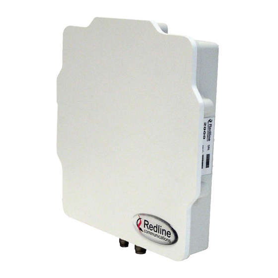
Page 10: System Overview
Ethernet network using a standard outdoor approved Ethernet cable. For each PTP link, one RDL-2000 is configured as Master Unit (MU) and controls the wireless link. This function is transparent to all Ethernet operations. The Master uses a... -
Page 11: Ethernet Ports
Ethernet cable is 91.5 m (300 ft). For example, 90 m (295 ft) from the RDL-2000 to the PoE and 1.5 m (5 ft) from the PoE to the network equipment. Figure 2: System - RDL-2000 Ethernet Ports The RDL-2000 Ethernet port uses a custom pinout for the PoE signals. -
Page 12: Indoor Poe Power Adapter
24. Indoor PoE Power Adapter The RDL-2000 is powered using a PoE power adaptor. The Redline supplied PoE power adaptor source is auto-sensing 110-240 VAC (nominal). The RDL-2000 is shipped with a power cord compatible with the North American power system. -
Page 13: Ground Connection
Ethernet equipment directly to the OUTPUT (DATA & POWER) connector on the PoE power adapter may damage customer equipment. Ground Connection A ground-lug is provided on the RDL-2000 chassis for connection to the local grounding system. Mounting Brackets The heavy-duty (four-point) mounting bracket can be used to mount the RDL-2000 and a flat panel antenna. -
Page 14: Rf Cable Connections
RF Cable Connections Two RF jumper cables are provided with each RDL-3000 unit. The RF cables conduct RF signals between the RDL-2000 and antenna system. Each 75 cm (29.5 in) cable is terminated female N to BNC. Figure 5: System - RF Jumper Cable... -
Page 15: Link Manager
IP address of the RDL-2000. Click S on the command bar to start a session. Select the RDL-2000, select user type Admin, enter the (default) password admin, and click Login to begin a session. -
Page 16: Connecting Through A Gateway
Password (default is admin), and check the box .Use Gateway. Click Login to begin a session. The Link Manager should connect to the RDL-2000. It the connection is not successful, refer to the Link Manager event log. Click E on the command bar to end the session. -
Page 17: Action Menu
RDL-2000 User Manual 3.2.3 Action Menu Start Session: Start a session with an RDL-2000 (CTRL-S). Choose an RDL-2000 unit discovered by the Link Manager, enter the required credentials, and click Login to begin a session. The Start Session function scans the entire subnet on the local network to identify RDL- 2000 units. -
Page 18: Tools Menu
Select Adapter: Choose a network interface card (NIC) on the computer running the Link Manager application. The selected interface is used to scan the local network for connected RDL-2000 units. The operator may also specify a network gateway (see the View menu item Login Bar. -
Page 19: Toolbar
Tools -> Select Adapter). Terminate the current session. : Retrieve current settings from the RDL-2000. : Reconnect automatically to the RDL-2000 if the session is lost for any reason (e.g., RDL-2000 reboots). Clicking this button toggles between enabled and disabled state. -
Page 20: Unit Status Bar
Channel: Indicates the RF channel in-use. RSSI: Received signal strength for this link. PER: Wireless packet errors for this link (after ARQ). Note: When the connection to an RDL-2000 is closed, the Link Manager continues to display the last received RSSI and PER values. 70-00143-01-01a Proprietary Redline Communications ©... -
Page 21: System Menu
RDL-2000 User Manual System Menu The screens are accessible using the menu located on the left side of the screen. Figure 12: Link Mgr - Screen Menu 70-00143-01-01a Proprietary Redline Communications © 2010 Page 21 of 50 September 20, 2010... -
Page 22: Installation Screen - Basic
MAC Address: Hardware (MAC) address of the connected RDL-2000. This address is also recorded on the RDL-2000 chassis label. IP Address: IP address for this RDL-2000. The IP address is routable through the Ethernet port and over the wireless interface. - Page 23 For the Master setting, refer to the MU ID setting in section 3.5: Advanced Screen on page 24. Important: If an RDL-2000 is replaced for any reason, the replacement unit must be programmed with the same link identification number. Operational Mode: Indicates the current status of the RDL-2000.
-
Page 24: Advanced Screen
Figure 16: Link Mgr - Advanced Installation Screen - Slave General Configuration Admin Login Password: Use this field to change the Admin password on the connected RDL-2000. You must be logged in as Admin to change the password. 70-00143-01-01a Proprietary Redline Communications © 2010... -
Page 25: Ethernet Configuration
RF channel. Ethernet Configuration See Figure 4: System - RDL-2000 RF Ports on page 13 for port identification. Port 1 Configuration: Select the operating mode of port 1. Note: This port is sealed at the factory. Do not remove this seal -- use Ethernet port 2 for normal operation. -
Page 26: Power Control (Atpc)
RDL-2000 unit. Disabled ( ): RDL-2000 unit does not recognize VLAN tagged management traffic. Enabled ( ): RDL-2000 unit can be managed using VLAN traffic tagged with the VID specified in the Mgmt. VID field (see Installation->Link Configuration screen). Ethernet traffic is blocked between Ethernet Port 1 and 2. -
Page 27: Regulation
Set Default: Click this button to reset the IIS value to the factory default value. Submit: Click this button to send the current parameter settings on this screen to the RDL-2000. The RDL-2000 will save these settings in non volatile RAM. All unsaved changes are discarded when the operator changes to another screen. -
Page 28: Link Configuration Screen
Link Configuration Screen Use this screen to configure advanced features including encryption and channel size. This screen is displayed only when a session is active to the RDL-2000. The information displayed is different for the Master and Slave. Figure 17: Link Mgr - Link Configuration Screen - Master Figure 18: Link Mgr - Link Configuration Screen - Slave MU ID: (Master only) Enter the identification number for this wireless link. -
Page 29: Master Parameters
(a-z, 0-9). This field is used only when AES is enabled. Notes: 1. The Master and Slave RDL-2000 units must have identical encryption settings or the system will not establish a wireless link. 2. The default key is the text "SharedKey". -
Page 30: Current Rate
Get Parameters: Click this button to read the current settings from the RDL-2000. Submit Parameters: Click this button to send the current parameter settings on this screen to the RDL-2000. The RDL-2000 will save these settings in non volatile RAM. All unsaved changes are discarded when the operator changes to another screen. -
Page 31: Software Screen
User Manual Software Screen Use this screen to view information about the software files loaded on the RDL-2000. The RDL-2000 contains non-volatile RAM storage for two versions of system software. The active software banks (versions loaded at power-up/reboot) are highlighted in yellow. -
Page 32: Firmware Screen
User Manual Firmware Screen Use this screen to upload new software files to the RDL-2000 and to change the software being loaded at power-up/reboot. The RDL-2000 contains non-volatile RAM storage for two copies of the system software, allowing updated software to be uploaded without interrupting the current operation. -
Page 33: Upload Procedure
Upload Procedure Use the following procedure to upload a software file. 1. Login to the RDL-2000 and click Firmware in the main menu (left side of screen). 2. Use one of the following methods to select the file: a) Drag & drop the file on this screen, or b) Click the Browse button to locate the file. -
Page 34: License Screen
10 MHz channel, 5.8 GHz band, and DFS enabled. Before entering a license file, the RDL-2000 is operating in a restricted mode and allows operation only in the 5.8 GHz band. License files are created using the MAC address of a specific RDL-2000 unit, and the license will be accepted only by an RDL-2000 having this MAC address. -
Page 35: Spectrum Sweep
This function should be performed only during installation or a scheduled maintenance window. This test can only be performed using a local connection to the RDL-2000. No user data is transmitted over the wireless link while this test is running. This operation requires a system reboot. -
Page 36: Tests
Transmit Rate: Click & hold to move the slider and adjust the transmit rate. The rate can be modified while the test is running. IP Address: Enter the IP address of the PC connected to the remote end RDL-2000. Tx: Click this button to start transmitting. -
Page 37: Ping
Send: Number of ping messages transmitted during the test. Received: Number of ping responses received during the test. Latency: Average round trip response time during the test. 70-00143-01-01a Proprietary Redline Communications © 2010 Page 37 of 50 September 20, 2010... -
Page 38: Debug
Queue Length (Bytes): Maximum amount of Tx data that has been saved in the Tx queue. Tx packets are dropped if this length exceeds the Max Queue Length. Requests (Packets): Number of ARQ requests received. 70-00143-01-01a Proprietary Redline Communications © 2010 Page 38 of 50 September 20, 2010... -
Page 39: Tx Power Control
RDL-2000 by clicking the Submit button. RF Attenuator (0-31): Use this setting to attenuate the signal. Changes made using the up/down controls are sent immediately to the RDL-2000. Values entered in this field are sent to the RDL-2000 by clicking the Submit button. -
Page 40: Troubleshooting
Reset text cleared by PC Link Manager has sent command to clear the Reset Text field (Action->Clear Reset Text). Reset text corrupted The RDL-2000 has been power cycled. Resetting the unit to perform ACS User selected Perform ACS. Scan stopped Spectrum sweep stopped by operator. -
Page 41: Recovering From A Lost Ip Address
RDL-2000 User Manual Recovering From a Lost IP Address If the password is known, the RDL-2000 can easily be recovered from the lockout causes listed below. Table 7: Maintenance - Recovery from System Lockout Symptom Recovery IP address is unknown. -
Page 42: Cli Interface
Note: The CLI does not support all features necessary to configure and operate the RD- 2000. Use the Link Manager applications to deploy and monitor the RDL-2000 units. CLI Command Summary The following table contains a summary of available CLI commands. -
Page 43: Starting A Telnet Session
Telnet provides the operator with basic monitoring capabilities from a remote workstation (platform independent). Configure the PC Ethernet adapter (NIC) to be in the same subnet as the RDL-2000. For example, if the RDL-2000 is using the default address 192.168.25.2, set the PC to address to 192.168.25.10. - Page 44 This function not supported in this release. firmware <[blank] | file.brn> View the firmware versions or upload a new binary file. The RDL-2000 contains non- volatile storage for two versions of the software. The upload function overwrites the non-operational version.
- Page 45 (can not specify a path). When the transfer has completed successfully, use the switchbanks command to enable the new software version. Example: Upload the software binary file abc.brn to the inactive bank on the RDL-2000: [192.168.25.2] >>: firmware abc.brn id <id_value>...
- Page 46 Adaptive Modulation is disabled, the RDL-2000 uplink rate is fixed at this modulation/coding. When Adaptive Modulation is enabled, this setting is ignored. Example: Set the RDL-2000 rate to downlink = 64 QAM 5/6 and uplink = 64 QAM 2/3: [192.168.25.2] >>: rate 7 5 reset Reboot the RDL-2000.
- Page 47 Activate and permanently save (non volatile RAM) all changes to the system parameters. Saving changes to some parameters will automatically reset the RDL- 2000. Example: Activate and save all parameter changes: [192.168.25.2] >>: update 70-00143-01-01a Proprietary Redline Communications © 2010 Page 47 of 50 September 20, 2010...
-
Page 48: Reference Information
Actual Ethernet data throughput is dependent on factors including: protocols, packet size (1916 bytes max.), burst rate, transmission latency, and link distance. Total distance from RDL-2000 port to PoE port. Determined be factory installed hardware. All specifications are subject to change without notice. - Page 49 RDL-2000 User Manual 70-00143-01-01a Proprietary Redline Communications © 2010 Page 49 of 50 September 20, 2010...
- Page 50 302 Town Centre Suite 100 Markham, Ontario Canada L3R 0E8 302 Town Centre Suite 100 Markham, Ontario Canada L3R 0E8 www.redlinecommunications.com www.redlinecommunications.com 70-00143-01-01a Proprietary Redline Communications © 2010 Page 50 of 50 September 20, 2010...
Need help?
Do you have a question about the RDL-2000 and is the answer not in the manual?
Questions and answers