Table of Contents
Advertisement
Quick Links
Advertisement
Table of Contents

Related Manuals for MSI Dyna-Link 2


Summary of Contents for MSI Dyna-Link 2
- Page 1 Presented By Dallas Ft Worth Austin Houston NicolScales.com 800.225.8181 Contact Us Nicol Scales & Measurement is an ISO Accredited Calibration Company that has provided calibration, repair and sales of all types of weighing and measurement products since 1931.
- Page 2 MSI-7300 Dyna-Link 2 Tension Dynamometer Operator’s Manual PN 152160 Rev C...
-
Page 4: Table Of Contents
Contents Introduction ................1 1.1 Safety ..................2 1.2 Key Descriptions ................ 3 1.3 General Information ..............4 1.4 MSI-7300 Annunciators ............. 6 1.5 Specifications ................7 1.5.1 Standard Capacities and Resolution ..........8 1.6 Features ..................9 1.7 Options ..................10 1.8 Unpacking ................ - Page 5 7.2 Error Codes ................48 7.3 Mechanical Dimensions ............49 7.4 Firmware Update Procedure ........... 50 The MSI Limited Warranty ............52 Rice Lake continually offers web-based video training on a growing selection of product-related topics at no cost. Visit www.ricelake.com/webinars.
-
Page 6: Introduction
1.0 Introduction The MSI-7300 Dyna-Link 2 is a combination of the sound and proven mechanical design of the industry standard Dyna-Link with today’s most advanced electronics to provide a superb feature set unmatched by any dynamometer in its class or price range. -
Page 7: Safety
"MSI Crane Scale Safety and Periodic Maintenance Manual" (available at www.msiscales.com). Keep hands, feet and loose clothing away from moving parts. There are no user serviceable parts within the Dyna-Link 2. Any repairs are to be performed by qualified service personnel only. MSI-7300 Operator’s Manual... -
Page 8: Key Descriptions
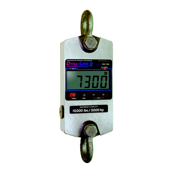
LCD Tension Display Units with maximum capacity of 100000 lb and up come with a 6 digit 1 in (26 mm) display. Figure 1-1. MSI-7300 Front Panel 1.2 Key Descriptions Dyna-Link 2 Power Key - Turns the on and off. -
Page 9: General Information
YYYYY programmed to all available user functions. 2. If a function key does not work, it is probably because the Dyna-Link 2 is not setup to support the key. For example, if the Function key is set for TOTAL, you must also setup the TOTAL mode in the setup menu. - Page 10 Top shackle interface 7300 Cotter pins Battery access cover MAXIMUM CAPACITY 5000 lbs / 2500 KG Bottom shackle interface RS-232 port Figure 1-2. Dyna-Link 2 Introduction...
-
Page 11: Msi-7300 Annunciators
1.4 MSI-7300 Annunciators The Dyna-Link 2 uses LCD annunciators to indicate tension mode and other information. Stable – indicates the tension force has settled within the motion window (usually ±1d). When standstill is off, the link will not zero, tare, or totalize. -
Page 12: Specifications
“LCnt” for load cell counter; test function shows the two readings in order. Table 1-1. MSI-7300 Specifications The MSI-7300 has a safe mechanical overload of 200% of capacity. WARNING Overloads greater than 200% may result in physical damage to the link. -
Page 13: Standard Capacities And Resolution
100 lb 5500 440% Steel 225000 kg 100 kg 2250 50 kg 4500 3 D-Cells 225 Ton 0. 1 T 2500 0.05 T 5000 2206 kN 1 kN 2206 0.5 kN 4412 Table 1-2. Standard Capacities and Resolutions MSI-7300 Operator’s Manual... -
Page 14: Features
• Shackle stops ensure ease of mounting. The stops prevent the shackles from falling to the side of the unit and are held in position for easy rigging. • MSI’s ScaleCore technology provides precision, high resolution (2500 division standard and up to 10,000 possible) 24 bit A/D conversion coupled with an advanced RISC microcontroller. -
Page 15: Options
6. Remove the battery access port cover with a coin or a large screwdriver. 7. Insert the two batteries, positive end first, into the battery shaft. 8. Reinstall the battery access port cover. The Dyna-Link 2 is now ready for use. The Dyna-Link2 will automatically start when the batteries are installed. -
Page 16: Battery Replacement
Dyna-Links large enough for ‘D’ cells. The use of NiCad batteries is not recommended. If the Dyna-Link 2 will not be used for an extended period, the batteries should be removed. A small current is used when powered off which will discharge the batteries in about six months. -
Page 17: Operation
The Dyna-Link 2 is ready for use. 2.2 Zero Takes out small deviations in zero when the Dyna-Link 2 is unloaded. See Section 3.6 for zeroing (Taring) package or pallet weights. The tension reading must be stable within the motion window for the zero function to work. -
Page 18: User Key Functions (F1And F2)
3.0 User Key Functions (F1and F2) There are optional functions that can be programmed for the function keys ( ) on the front panel, as well as on the RF remote display. See Section 4.2 for setup instructions. The functions PRINT (F3), and TARE are available full time on the RF remote display. -
Page 19: Auto Total
The TARE Fx-TARE TARE function in the Dyna-Link 2 is defined as a tare-in/tare-out operation. The first press of the key stores the current tension/weight as a tare value and then the Fx-TARE Dyna-Link subtracts the tare value from the gross tension and changes the display to mode. -
Page 20: To Tare And Display The Net Tension
3. The digits display 0 and the tension mode changes to 4. The backup memory in the Dyna-Link 2 stores the tare reading, and can restore it even if power fails. 3.6.2 To Clear the Tare and Revert to Gross Tension 1. -
Page 21: 2-Units/ 5-Units
Figure 3-1. Capture Peak Force 2-UNITS/ 5-UNITS key will switch the force units between pounds force and kilograms Fx-2.Unit force. Selecting the setting will scroll through all available units: lb, kg, Fx-5.Unit tons (U.S. short), metric tons, and kilonewtons. MSI-7300 Operator’s Manual... -
Page 22: Hi-Res
Hi-res mode will make the ZERO Dyna-Link 2 more sensitive to motion and movement resulting in a less stable display. When hi-res is on, the filter is automatically set to the Hi-1 setting (if Hi-2 is already set, then the filter is not changed). -
Page 23: Dyna-Link Setup
Totals the highest stable load Autototal Last and Autototal High total when the scale is unloaded. Pounds Weight Units kilograms (disabled) Short Tons Metric Tons High Filter kiloNewtons Very High Filter SOFTWARE FILTER Figure 4-1 MSI-7300 Menu Map MSI-7300 Operator’s Manual... -
Page 24: Function Keys
4.2 Function Keys The Dyna-Link 2 has two user definable function keys on the front panel that can be programmed to several different functions. F1 is defaulted to peak hold, and F2 is defaulted to test. This procedure also assigns the F1 & F2 keys on the optional RF remote display. -
Page 25: Auto-Off
Next Setup Menu Item 6) Either press ZERO to exit setup and store all changes, or EXIT/SAVE continue to another setup menu item using the key. ZERO Store and return to weight display Figure 4-3 Auto-Off Setup MSI-7300 Operator’s Manual... -
Page 26: Setpoints
4.4 Setpoints The Dyna-Link 2 supports two setpoints. Common uses of set points are for warnings or process control. The MSI-7300 Dyna-Link 2 comes standard with two high brightness red LED outputs for a triggered set point. The MSI-7300 Dyna-Link 2 has an audible output option that is triggered by setpoint 1. - Page 27 10)Either press ZERO to exit setup fixed next setup menu item and store all changes, or EXIT/SAVE Store and return to continue to another setup menu weight display item using the key. ZERO Figure 4-4 Setpoint Setup (continued) MSI-7300 Operator’s Manual...
-
Page 28: Total Mode
4.5 Total Mode The MSI-7300 Dyna-Link 2 can keep track of all weighments using the total feature. Either manual total, which totals by pushing a configured key on the front USER panel or the optional RF remote display, or auto-total which can be used to automatically add up each weighment. -
Page 29: Units
EXIT/SAVE 6)Either press ZERO to exit setup and store all changes, or continue to another setup menu ZERO Store and return to item using the key. weight display Figure 4-6 Units Select Menu MSI-7300 Operator’s Manual... -
Page 30: Filter Setup
If the reading is not stable, it can often be improved by increasing the filter setting. Settling time will be longer as the filter setting is increased. However, the MSI-7300 Dyna-Link 2 employs algorithms that speed up large tension changes while still controlling vibration even with higher filter settings. -
Page 31: Calibration
500kg test weight to calibrate a 5000kg capacity unit. The Dyna-Link 2 supports load cell linearization with up to four span points that can be calibrated in any order. Usually only one cal span point is necessary and is sufficient to reach rated accuracy. - Page 32 Procedure for the Routine Calibration of the MSI-7300 Press 1) With the power on, initiate Simultaneously calibration by holding down ZERO keys until the display reads CAL. ZERO The CAL setup menu appears. 2) Press to start the calibration procedure.
- Page 33 ZERO parameters Cal saved to memory (Standard, AZM, etc.) You can cancel calibration by pressing Power and the scale will reset to the previous calibration constants. Figure 5-2 Standard Calibration Procedure (continued) MSI-7300 Operator’s Manual...
-
Page 34: Initial Calibration
5.2 Initial Calibration Use this procedure only if the capacity and count-by ( ) needs to be modified. The initial steps of this procedure will totally erase user setups as well as any previous calibration. Resetting Capacity and Countby (d) Press &Hold 1) Turn the 7300 on. - Page 35 F1. The UnLd display appears and the scale is ready for calibration. Follow the standard Proceed to Standard calibration procedure Calibration starting at Step 3. starting at step 3. Figure 5-3 Initial Calibration (continued) MSI-7300 Operator’s Manual...
-
Page 36: Guidelines For Capacity And Resolution
The third way is to increase the motion window. The MSI-7300 Dyna- Link 2 defaults to ±1d as a motion window. It can be changed at MSI to a higher value if desired. Often ±3d is chosen for bridge cranes as these tend to have a lot of bounce to them. -
Page 37: C-Cal Calibration
C-Cal number must be known. MSI supplies replacement load cells for the MSI-7300 Dyna-Link 2 with the C-Cal value stamped on the serial number label. When a calibration is preformed with test weights, a new C-Cal is generated. - Page 38 SCROLL ENTER/SELECT LCD will read PASS. Multiple C-Cal span points are fixed possible, but are only accessible using MSI’s ENTER/SELECT optional SCCMP program. 10) When the final C-Cal number is finished, press ZERO to exit and save...
-
Page 39: Auto Zero Maintenance (Azm)
5.5 Auto Zero Maintenance (AZM) The Dyna-Link 2 employs an auto zeroing maintenance mechanism to adjust the zero reading to the center-of-zero (COZ). COZ is defined as the tension reading is within ¼’d’ of zero. AZM continuously adjusts zero to maintain COZ. It is recommended that AZM is on to maintain the highest accuracy. -
Page 40: Service Counters
Figure 5-6 Access the Service Counters Only a MSI factory representative can reset the service counters, WARNING as these are important safety warning features. Depending on the circumstances, a thorough load train inspection might be necessary to ensure user safety. -
Page 41: Communication Setup
Only one communications type can exist at a time. The RS-232 port located on the bottom side of the Dyna-Link 2 is useful for setup and calibration using a computer and MSI’s SCCMP Software (SCCMP operation is detailed in the SCCMP User Guide). -
Page 42: Printer Setup
The RS-232 comm port is capable of outputing tension data. All the weight modes the Dyna-Link can measure are available in user formatted form. The control mode program is what causes the Dyna-Link 2 to print. • USER – the assigned F-Key is pressed, then one transmission of the selected string type is output. -
Page 43: Standard Print Strings
See the ScCMP programming guide for details. ScCMP programming can be found on the CD included with the product or can be downloaded from the MSI website. The serial output is configured as 9600 baud, Xon/Xoff handshaking, no hardware handshaking, 1 stop bit, no parity. -
Page 44: Printer Output Setup
6.2.2 Printer Output Setup 1) With the 7300 on, press the key simultaneously. ZERO Press and Hold ENTER/SELECT 2) The LCD shows Print. Press 1= Current Wt (Wt-Unit-Mode 2= Net Wt (Wt-Unit-Net ENTER/SELECT 3) The submenu item StrnG 3= Gross Wt (Wt-Unit-Grs appears. - Page 45 Item appears, String. EXIT/SAVE EXIT/SAVE 15) Exit the print setup menu by pressing ZERO twice. The message Store appears briefly ZERO ZERO then normal link operation starts. Figure 6-3 Print Output Setup (continued) 40 MSI-7300 Operator’s Manual...
-
Page 46: Comm Port Hardware
6.3 Comm Port Hardware The Dyna-Link 2 RS-232 comm port is used for software updates, connecting to a remote display, and for connecting to any RS-232 device. Connector M12 industrial IP67 rated. An adapter cable (P/N 503363) is Dyna-Link 2 required to connect the to a computer. -
Page 47: 802.15.4 Rf Network Setup
3. Network ID – this is a 64-bit number that all interconnected devices must match. The Dyna-Link 2 limits this number to a max of 5 digits for a range of 0 - 99999. Do not use a small number here to help avoid other 802.15.4 networks that default to a network ID of 0. - Page 48 If the offered SCID value is correct, push and jump to step 10. In this example we’ll enter 3 as an SCID number. Any value from 1-254 is acceptable. However, MSI recommends a value from 20 – 30. SCROLL 7) To input the SCID value, press...
- Page 49 Press to start a new number. Allowed network ID numbers range from 0 to 99999. MSI recommends a random number of at least four digits to ensure that the 8000 system won’t conflict with any example value only other 802.11.4 networks (Zigbee).
-
Page 50: Fcc Statement (For 802.15.4 Option)
6.5 FCC Statement (For 802.15.4 Option) Contains FCC ID: OUR-XBEEPRO The enclosed device complies with part 15 of the FCC rules. Operation is subject to the following two conditions: (i.) this device may not cause harmful interference and (ii.) this device must accept any interference received, including interference that may cause undesired operation. -
Page 51: Appendix
Excessive side loading Improve load train symmetry Load cell faulty Check LC connections Display toggles between Tension exceeds capacity Immediately reduce tension “Error” and “Load” Faulty load cell or wiring Check LC and LC wiring. Table 7-1. Troubleshooting MSI-7300 Operator’s Manual... - Page 52 Link increment “d.” It is also possible to increase the motion window. Contact MSI if you have a problem getting the MSI-7300 to zero, tare, or total due to stability issues. Setpoint lights blink Setpoint is enabled and the Disable setpoints if they are not...
-
Page 53: Error Codes
7.2 Error Codes The ScaleCore processor that is the heart of the MSI-7300 Dyna-Link2 detects errors and generates error codes to aid in troubleshooting. Error Code Definition Comment LcOFF LC Disabled A load cell was not enabled 2CAL In Cal The system is in calibration mode. -
Page 54: Mechanical Dimensions
Mechanical Dimensions C = DIA. 7300 E = LOAD CELL BODY WIDTH AT MAXIMUM CAPACITY 5000 lbs / 2500 KG SHACKLE INTERFACE. Figure 7-1. Mechanical Dimensions Approx Capacity Shackle Shipping 1000 lb 8.0 in 13.53 in .75 in 5 in .99 in 1.69 in 1.75 in... -
Page 55: Firmware Update Procedure
The latest firmware code is available from the MSI service department and can be emailed on request. Your firmware version is displayed when the MSI-7300 is turned on in the form of “01-04”... - Page 56 ” to restore the boot menu. MSI8000 SCALECORE2 BOOT LOADER Ver. 00-05 (c) 2012-05-02 10:55 (u) Download and program application code (your bootloader version may vary) (q) query app code info (g) execute app code refresh 11.Send a “ .” The MSI-7300 should start. Appendix...
-
Page 57: The Msi Limited Warranty
The MSI Limited Warranty MEASUREMENT SYSTEMS INTERNATIONAL, INC., WARRANTS load sensing elements and meters against defects in workmanship and materials for a period of one year from date of purchase and warrants electrical cables and batteries against the same defects for a period of ninety (90) days from date of purchase. - Page 58 Notes Appendix...
- Page 59 Notes MSI-7300 Operator’s Manual...
- Page 61 Measurement Systems International A RICE LAKE WEIGHING SYSTEMS COMPANY 14240 Interurban Avenue South Suite 200 Seattle, WA 98168-4661 Phone: 206-433-0199 Fax: 206-244-8470 www.ricelake.com www.ricelake.mx www.ricelake.eu www.ricelake.co.in m.ricelake.com © Rice Lake Weighing Systems 06/2015 PN 152160 Rev C...
Need help?
Do you have a question about the Dyna-Link 2 and is the answer not in the manual?
Questions and answers