
Subscribe to Our Youtube Channel
Related Manuals for Campbell CH150


Summary of Contents for Campbell CH150
- Page 1 PS150/CH150 12 V Charging Regulators Revision: 10/17 C o p y r i g h t © 2 0 0 0 - 2 0 1 7 C a m p b e l l S c i e n t i f i c ,...
- Page 3 Limited Warranty “Products manufactured by CSI are warranted by CSI to be free from defects in materials and workmanship under normal use and service for twelve months from the date of shipment unless otherwise specified in the corresponding product manual. (Product manuals are available for review online at www.campbellsci.com.) Products not manufactured by CSI, but that are resold by CSI, are warranted only to the limits extended by the original manufacturer.
- Page 4 (435) 227-9106. Campbell Scientific is unable to process any returns until we receive this form. If the form is not received within three days of product receipt or is incomplete, the product will be returned to the customer at the customer’s expense.
- Page 5 Periodically (at least yearly) check electrical ground connections. • WHILE EVERY ATTEMPT IS MADE TO EMBODY THE HIGHEST DEGREE OF SAFETY IN ALL CAMPBELL SCIENTIFIC PRODUCTS, THE CUSTOMER ASSUMES ALL RISK FROM ANY INJURY RESULTING FROM IMPROPER INSTALLATION, USE, OR MAINTENANCE OF TRIPODS, TOWERS, OR ATTACHMENTS TO TRIPODS AND TOWERS SUCH AS SENSORS, CROSSARMS, ENCLOSURES, ANTENNAS, ETC.
-
Page 7: Table Of Contents
The PS150 connected to a CR1000 and AC power ......3 3-2. The PS150 connected to a CR1000 and solar panel ......4 3-3. CH150 connected to BP24 battery pack and CR1000 ......4 3-4. Solar panel connections on PS150 ............5 3-5. - Page 8 Table of Contents 7-1. Null modem connections ..............15 7-2. PS150 with A100 module using a COM220 and RF450 ....15 8-1. A105 adapter ..................16...
-
Page 9: Introduction
AC/DC converters, it is undesirable for wind turbines because of the resulting free spinning when unloaded. Consequently, series charging regulators, including the PS150/CH150, should not be used to regulate the output of wind turbines without the inclusion of a way to load the turbine when the batteries require little or no charging current. -
Page 10: Precautions And Tips
VRLA battery manufacturers state that “Heat Kills Batteries”. While the PS150/CH150 can operate from –40 to 60 °C, optimum battery life is achieved with battery operating temperatures ranging from 5 to 35 °C , per manufacturer’s recommendations... -
Page 11: Quickstart
The PS150/CH150 modules are designed to handle extreme conditions. The modules have been designed with mounting holes on one inch centers for mounting to a standard Campbell Scientific enclosure back plate — see the enclosure manual for mounting suggestions. See FIGURE... -
Page 12: The Ps150 Connected To A Cr1000 And Solar Panel
PS150/CH150 12 V Charging Regulators FIGURE 3-2. The PS150 connected to a CR1000 and solar panel FIGURE 3-3. CH150 connected to BP24 battery pack and CR1000... -
Page 13: Connecting Power
Remove rings, watches, or bracelets before hooking up power and connecting a battery. Unlike earlier Campbell Scientific power supplies, the CH/PS150 can have both solar and AC power hooked up simultaneously. Flip the power supply switch to Off before hooking up power to the power supply. -
Page 14: 3.1.2 Ac/Dc Power
PS150/CH150 12 V Charging Regulators 3.1.2 AC/DC Power Double check the input voltages coming in to the charger/regulator with a volt meter. AC Input Voltage: 14 to 24 Vac RMS DC Input Voltage: 15 to 40 Vdc WARNING Exceeding the voltages listed above will damage the power supply. -
Page 15: Lift Latch Up On Ps150
PS150/CH150 12 V Charging Regulators WARNING Do not remove the tape holding the battery wiring harness to the top of the battery! The tape is used to keep the battery wiring harness out of the way of the rubber bumpers on the inside of the lid. -
Page 16: Hook Up Power To Datalogger
FIGURE 3-8. Wiring harness plugged into battery connector Hook Up Power to Datalogger Both the PS150 and the CH150 come with a 1-foot black wire attached to one of the G terminal blocks and a 1-foot red wire attached to one of the 12V terminal blocks. -
Page 17: Led Indicator
PS150/CH150 12 V Charging Regulators LED Indicator The green Charge LED will flash approximately once a second if all incoming connections are correct and there is an adequate charging voltage present. Specifications Specifications (CHARGE - CHARGE terminals) AC – (18 to 24) VRMS internally AC or DC Source: limited to 1.2 ARMS... -
Page 18: Battery Packs
–40 to +71 Concorde Sun Xtender * Battery specifications shown are from the manufacturer. The PS150/CH150 contains charging algorithms that optimize battery charging over the range of –40 to 50 °C. Battery usage outside of manufacturer specifications could have unknown effects on the life of the battery. - Page 19 3.6 Adc. CHARGE/CHARGE terminal blocks have no polarity. Power wires from the charging source can be connected in any fashion. The PS150/CH150 will only float charge a battery with power connected to the CHARGE/CHARGE terminal blocks which is fine when using an AC/DC charging source.
-
Page 20: Operational Overview
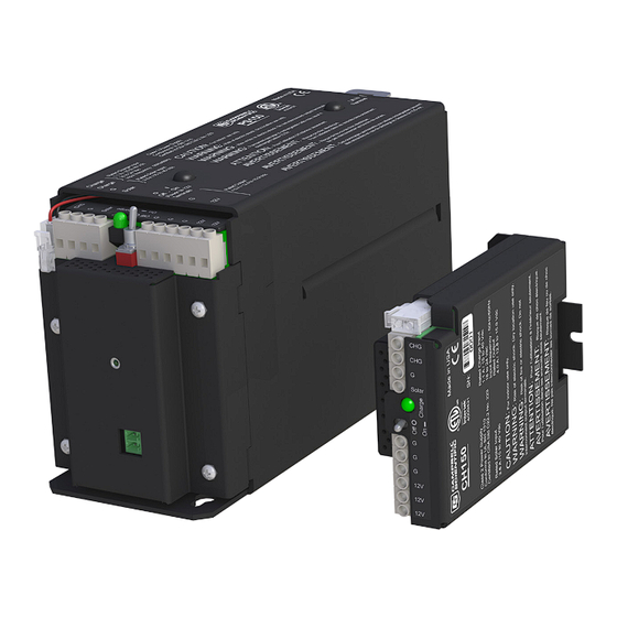
FIGURE 5-1. A 12-V 7Amp-hr rechargeable battery is included with the PS150, whereas the user provides the rechargeable battery, such as the BP12 or BP24 offered by Campbell Scientific, Inc., for the CH150. See Section 4.2, Battery Packs , for rechargeable batteries offered for the CH150 by (p. -
Page 21: Charging Details
Continuous charging input has a maximum value of 1.1 Adc to help protect AC/AC transformers and AC/DC converters. The 3.6 Adc typical current limit of the PS150/CH150 Solar charging input is well suited for 70 W solar panels. Typical Continuous charging inputs would be AC/AC transformers or AC/DC converters in which a charge voltage is continuously applied except for line power outages. -
Page 22: Maximum Power Point Tracking
The ports are used to connect two 9-pin devices (e.g., modems or RF radios) that would normally be connected to the CS I/O port of a Campbell datalogger. The charger supplies 12 Vdc and 5 Vdc to the appropriate pins on the connector for powering the connected devices. -
Page 23: A105 Additional 12 V Terminals Adapter
A105 Additional 12 V Terminals Adapter The A105 adapter adds four 12 V terminals and four ground terminals to a PS150/CH150 charging regulator. The extra terminals make it easier to wire multiple continuously powered 12 Vdc devices to the power supply. -
Page 24: References
PS150/CH150 12 V Charging Regulators FIGURE 8-1. A105 adapter References 1 – Genesis Application Manual – Genesis NP and NPX Series US-NP-AM- 002, June 2006. - Page 26 Santo Domingo, Heredia 40305 SOUTH AFRICA COSTA RICA • cleroux@csafrica.co.za • info@campbellsci.cc www.campbellsci.co.za www.campbellsci.cc Campbell Scientific Southeast Asia Co., Ltd. Campbell Scientific Ltd. 877/22 Nirvana@Work, Rama 9 Road Campbell Park Suan Luang Subdistrict, Suan Luang District 80 Hathern Road Bangkok 10250...
Need help?
Do you have a question about the CH150 and is the answer not in the manual?
Questions and answers