Table of Contents
Advertisement
Technical Manual
T H E R M O C O M P U T E R
Z 1
Z2
Z3
tmp 2
tmp 1
t 0
t 1
rmp1
prog
7
1050°C
4
memo
150°C
0
1
hold
event 1
shift
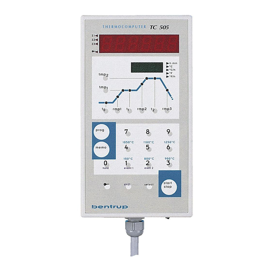
Programme Controller
TC 505 / TC507
> V1.30 (flat case)
TC
505
h.min
°C
°C/h
°F
°F/h
rmp2
rmp3
t 2
8
9
1180°C
1250°C
5
6
800°C
900°C
2
3
event 2
start
select
stop
TC 50 7
T H E R M O C O M P U T E R
Z1
Z2
Z3
seg#
value
R
N
tmp
prog#
time
rmp
dwell
prog
7
8
skip!
memo
4
5
0
1
2
p.hold
event 1
event 2
start
shift
select
stop
h.min
°C
°C/h
°F
°F/h
9
hold!
6
3
end
Advertisement
Table of Contents

Related Manuals for bentrup TC 505


Summary of Contents for bentrup TC 505
- Page 1 1050°C 1180°C 1250°C memo 150°C 800°C 900°C p.hold event 1 event 2 hold event 1 event 2 start shift select start stop shift select stop Programme Controller TC 505 / TC507 > V1.30 (flat case)
- Page 2 1. General Information In most applications the bentrup TC500 series controller (TC505 and TC507) can adapted by the controller configuration as described in the operating instructions Appendix C (simple configuration mode). However, some applications require controller features which can not be accessed by the simple configuration mode (Examples: Using motorized valvues, adapting error conditions etc.).
- Page 3 3. Changing Parameters in the Extended Configuration Mode Enter the configuration mode as usually (pess and hold key „select“ until display changes). The controllers display appears as shown: TC505 TC507 h.min seg# value °C h.min °C °C/h °C/h °F °F °F/h tmp 2 °F/h...
- Page 4 DO......digital output (e.g. switching output) DI......digital input (e.g. status input) AO ......analog output (e.g. 0-10V output) AI ......analog input (e.g. measure input) The number following this designator specifies the input/output. Examples: DO 0.0....1st switching output of the controller DO 0.1....2nd switching output of the controller AI 0.0 ....1st analog input (e.g.
- Page 5 5. Changing Parameters by a PC If your TC500 controller is fitted with a RS232 or RS485 interface you can use the free bentrup software WinConfig to do all parameter changes very easy. WinConfig makes parameter setting simple as well you can save configurations on disk and reload etc.
- Page 6 / calender is used to time stamp logged data and events. When configuring the controller using bentrup WinConfig / WinControl the controller is automatically updated with the PCs time / date information, Therefore manually changeing time / date is disabled...
- Page 7 (value range OFF to 62) Sets the communication ID of the controller. Affects external communication only. Make sure that this ID fits the setting in the communcation software (e.g. bentrup WinControl). Each ID must be unique on the communication network...
- Page 8 Table 2: analog input Specifies the analog input signals for the controller. Analog inputs are used to connect sensors like thermocouples, resistors, voltage/current signals to the controller. You can exactly define signal type (voltage, resistance, current) as well as signal range, signal conversion and correction, unit etc. The most common signal types are predefined.
- Page 9 value is respected as overrun (causing an error) following parameters apply on selection T/C only: 08: thermocouple (options S, R, K, J, B) Select the IEC code of the thermocouple used 09: external CJC (value range OFF, IN00 to IN03) Could junction compensation temperature.
- Page 10 Table 3: digital input Digital inputs can be used for different purposes. First they are used to create a process value depending on a frequency or number of pulses. Second they are used to control programme execution in different ways. Third, they are used by the optional PLC.
- Page 11 settings resp. reconnecting the outlets to a different position 02: destination (value range AO0.0 to AO0.2) Selects the physical output of the signal following parameters apply on selection PRZ only: 03: channel source (value range CH00 to CH02) Selects the control channel (loop) used to drive the output. The options MX../A resp. MX../G are the outputs of the air / gas mixer (for combustion units) 04: output charact (value range 0 to 4)
- Page 12 Table 5: digital output Digital outputs are used to switch any kind of ON/OFF devices as well as motorized valves (using 2 digital outputs in sequence). Depending on controller hardware the output is either a switching relay output (8A / 250V) or a logic output (OFF=0V / ON=12V).
- Page 13 Upper output signal limit. The output will never exceed this limit. Can be used for instance to limit the maximum heating of a kiln. Note that limiting can cause problems if the applications lacks of heating power (gradient check errors etc.) 08: cyclus time (value range 0 to 100) Cyclus time (in seconds) of the digital output.
- Page 14 set the parameters as follows: compare more = 0 / limit 1 = IN00 / limit 2 = SP00 / limit const = 30 23: limit 1 (value range OFF, SP00 to CH19) Selects the process value used as "limit 1" in the formula. This can be a setpoint, an actual temperature, a channel (loop) output or "OFF"...
- Page 15 Table 6: programme table The programme table determines the parameters and the sequence to be entered for each programme segment. The first programme parameter is always a time followed by a temperature. Depending on the application the following programme segment parameters could be for instance offset temperatures (for multizone kilns), programme events etc.
- Page 16 24: upper val. lim (value range -9999 to 9999) Upper limit of the programme table value. Used for instance to ensure the values entered by the user stay within the operation limits of the kiln following parameters apply on selection VAL-S only: 32: value unit (options °C, °F, °K, dg, mV, mA, O2, CO, %, ev, mb, m³, m³h, kh, kwh, Pa, AT) Specifies the unit of the programme table value...
- Page 17 temperature of 1000°C 03: num of matches (value range 1 to 250) An uncontrolled ramp (SKIP) is only completed if the temperature matched the specified number of cycles. The check is done each 0.5 seconds. This is used to avoid leaving the segment if the temperature only overshoots for a short time.
- Page 18 Table 8: programme setpoint The programme setpoints are calculated according to the programme resp. temperature curve entered by the operator. Some adjustments are possible for easy operation. Automatic setpoint calculation required for cascade control systems is also entered by the following settings 00: setpoint type (options END, CON, MOD, CHA) The following basic types creating a setpoint can be selected:...
- Page 19 following parameters apply on selection CHA only: 21: based on SP (value range SP00 to SP02) Selects the programme setpoint used for the cascade control, ie. the programme setpoing for the target 22: charg.ctrl.CH (value range CH00 to CH02) Selects the master control channel (loop). The basic idea of a cascade control is as follows: An application requires a large target (e.g.
- Page 20 03: power % on ERR (value range -100 to 100) Predefined process output if an error occurs in the control channel. The control channel enters error state if a.) the process value fails (overrun, underrun, invalid), b.) the process value exceeds the process value limit specified in the channel configuration or c.) the gradient check indicates failure 04: maximum value (value range 0 to 9999)
- Page 21 channel enters OFF status as long as heating applies 23: - activat. DOx (value range OFF, DO0.0 to DO1.0) Selects the bit (digital output) which activates the negative operation range (cooling). When the bit is off the channel enters OFF status as long as cooling applies following parameters apply on selection D-HYS only: 28: hyster.
- Page 22 DIx: Displays a group of 8 digital inputs AIx: Displays a group of 8 analog inputs MIXER: Displays the status of the atmosphere mixer FLWRT: Displays a flow ratio KWH: Displays the power pickup VOL.: Displays a media flow volume RTC: Displays real time / calendar PLC.S: Displays various PLC status information following parameters apply on selection VAL only:...
- Page 23 Selects the process value to be shown following parameters apply on selection KWH only: 131: power calc.CH (value range -CH02 to CH02 ) Selects either a single control channel of a range of control channels used for calculating power pickup. Negative channel number stands for CH00 to CH..
- Page 24 36: output sel.B (value range OFF, DO0.0 to DO1.0) As before, but selects between options 0/1 and 2/3. Set to "OFF" if not used ©2015 bentrup Industriesteuerungen. We reserve the right to change specifications without prior notice. Compiled JUN 24...
Need help?
Do you have a question about the TC 505 and is the answer not in the manual?
Questions and answers
Hello, we need this product. BENTRUP TC505