
Related Manuals for Tektronix TDS3SDI


Summary of Contents for Tektronix TDS3SDI
- Page 1 Technical Reference TDS3SDI 601 Digital Video Application Module 071-0689-00 This document supports firmware version 2.20 and above. www.tektronix.com...
- Page 2 Copyright © Tektronix, Inc. All rights reserved. Tektronix products are covered by U.S. and foreign patents, issued and pending. Information in this publication supercedes that in all previously published material. Specifications and price change privileges reserved. Tektronix, Inc., P.O. Box 500, Beaverton, OR 97077 TEKTRONIX and TEK are registered trademarks of Tektronix, Inc.
- Page 3 WARRANTY SUMMARY Tektronix warrants that the products that it manufactures and sells will be free from defects in materials and workmanship for a period of three (3) years from the date of shipment from an authorized Tektronix distributor. If a product proves defective within the respective period, Tektronix will provide repair or replacement as described in the complete warranty statement.
-
Page 5: Table Of Contents
......... . Appendix Appendix A: Specifications ......TDS3SDI 601 Digital Video Technical Reference... - Page 6 Table of Contents TDS3SDI 601 Digital Video Technical Reference...
-
Page 7: General Safety Summary
Do Not Operate in an Explosive Atmosphere. Safety Terms and Symbols Terms in This Manual. The following term appears in this manual: CAUTION. Caution statements identify conditions or practices that could result in damage to this product or other property. TDS3SDI 601 Digital Video Technical Reference... - Page 8 Do not slide sensitive components over any surface. Do not touch exposed connector pins. Handle sensitive components as little as possible. Transport and Store Carefully. Transport and store sensitive components in a static-protected bag or container. TDS3SDI 601 Digital Video Technical Reference...
-
Page 9: Preface
Preface The TDS3SDI 601 Digital Video application module provides additional functions to the TDS3000 series Digital Phosphor Oscilloscope. These new functions make it easier to capture, display, and measure video waveforms from both broadcast and non-broad- cast equipment. This Technical Reference describes the capabilities, operation, and applications of the 601 Digital Video module. -
Page 10: Contacting Tektronix
1-800-833-9200 6:00 a.m. – 5:00 p.m. Pacific time Or contact us by e-mail: support@tektronix.com For product support outside of North America, contact your local Tektronix distributor or sales office. Service Tektronix offers a range of services, including support Extended Warranty Repair and Calibration services. -
Page 11: Getting Started
Getting Started This section describes how to install and check the TDS3SDI 601 Digital Video application module. Installing the Application Module Firmware NOTE. You must do the firmware installation procedure the first time you install a new application module. If you do not update the oscilloscope firmware, the new application module may not function at all, or may not function correctly. - Page 12 NOTE. If you power off the oscilloscope, eject the floppy disk before prompted, or there is a power outage during the firmware upgrade process, you must restart the firmware upgrade procedure starting at step 2 on page 1. TDS3SDI 601 Digital Video Technical Reference...
- Page 13 Push MENU OFF to remove this message” 1. Push the MENU OFF button. 2. Eject the floppy disk. 3. You are done installing the firmware. Go to to Installing the Application Module on page 4. TDS3SDI 601 Digital Video Technical Reference...
-
Page 14: Installing The Application Module
Getting Started Installing the Application Module The following figures show how to install the TDS3SDI application module. CAUTION. Turn off power before installing or removing a module. To avoid damaging the oscilloscope or application module, observe the ESD precautions described on page iv. - Page 15 Getting Started ITU-R 601 TDS3SDI 601 Digital Video Technical Reference...
- Page 16 Getting Started CH 2 CH 3 CH 4 TDS3SDI 601 Digital Video Technical Reference...
-
Page 17: Checking Module Installation
Getting Started Checking Module Installation Do these steps to check that the TDS3SDI 601 Digital Video application module and firmware are correctly installed. 1. Power on the oscilloscope. Look at the oscilloscope startup screen; it should list the 601 module. If the oscilloscope displays... -
Page 18: Troubleshooting Module Installation
5. Reinstall the firmware (page 1). 6. Turn on the oscilloscope. If the oscilloscope still does not display the application menu items as listed in Checking Module Installation, power off the oscilloscope and contact the nearest Tektronix service center. TDS3SDI 601 Digital Video Technical Reference... -
Page 19: Operating Basics
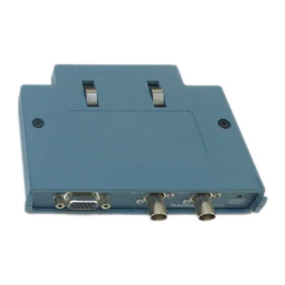
1 of the oscilloscope. You can also connect this signal to a video monitor. BNC connector for 601 video signal input. Green LED that lights when the module recognizes a valid 601 video signal. TDS3SDI 601 Digital Video Technical Reference... -
Page 20: 601 Digital Video Feature Overview
You can then manually adjust controls to optimize the display. Vectorscope Use the Vectorscope function with 100% and 75% color bars to analyze 601 digital, standard video, or analog HDTV color difference video signals using a familiar display format. TDS3SDI 601 Digital Video Technical Reference... - Page 21 1 and field 3. Custom Video Use the custom video function to specify custom horizontal scan rates in order to trigger on non-broadcast video waveforms, such as those used by computer monitors and medical equipment displays. TDS3SDI 601 Digital Video Technical Reference...
-
Page 22: Accessing 601 Video Functions
1. Push the UTILITY panel button. 2. Push the System bottom button to select Apps. 3. Push the Module button to select ITU-R 601. The bottom and side menus change to show the 601 functions. TDS3SDI 601 Digital Video Technical Reference... - Page 23 1. Push the Acquire MENU front panel button to display the Acquire menu. 2. Push the Autoset bottom button to display the Autoset side menu. 3. Push the Video Autoset side button to automatically display a composite video waveform triggered on all lines. TDS3SDI 601 Digital Video Technical Reference...
- Page 24 2. Push the Graticule bottom button to display the graticule side menu. Push the -More- button to display the IRE and mV buttons if they are not already displayed. 3. Select IRE or mV on the side menu. TDS3SDI 601 Digital Video Technical Reference...
-
Page 25: Reference
H The oscilloscope does not have video signal clamping. Tektronix offers an optional Video Display Clamp module (part number 013-0278-00) that provides video signal clamping. H The TDS3SDI module is optimized for the TDS3054 DPO oscilloscope. The module provides reduced performance in other TDS3000 Series oscilloscopes. -
Page 26: Video Quickmenu
The following tables describe the video QuickMenu. There are two video types in the SUBMENU button: ITU-R 601 and SDTV/HDTV. The following menu descriptions apply to both video types unless marked otherwise. TDS3SDI 601 Digital Video Technical Reference... - Page 27 (601 only) ACQUIRE Fast Trig Sets the acquisition mode to Fast Trigger (SDTV/HDTV (500 points). only) Normal Sets the acquisition mode to Normal (10K points). TDS3SDI 601 Digital Video Technical Reference...
- Page 28 Turning Picture Off returns the oscilloscope to the state prior to turning Picture On, except for any values changed while in Video Picture mode. Key Points DISPLAY Waveform. Pushing the Waveform button automatically turns off Video Picture or Vectorscope. TDS3SDI 601 Digital Video Technical Reference...
- Page 29 Displayed when HDTV is selected in 1080/24sF the Format side menu. 720p/60 480p/60 Holdoff Time Sets the trigger holdoff time value. Use the general purpose knob to change the holdoff time value. TDS3SDI 601 Digital Video Technical Reference...
- Page 30 Input Sets the oscilloscope to decode and trigger on (601 only) 525 or 625-line video signals. Auto Sets the oscilloscope to automatically detect and Detect trigger on either 525 or 625-line video signals. TDS3SDI 601 Digital Video Technical Reference...
- Page 31 For example, if you are triggering on an HDTV signal, then select the ITU-R 601 submenu, the oscillo- scope continues to use the HDTV trigger setting until you select a trigger in the ITU-R 601 side menu. TDS3SDI 601 Digital Video Technical Reference...
-
Page 32: Alternating Trigger Source Function
If one or more of the source signals do not meet the trigger settings, the oscilloscope either waits for that source channel to trigger (Normal trigger mode) or autotriggers (Autotrigger mode). TDS3SDI 601 Digital Video Technical Reference... -
Page 33: New Functions In The Video Trigger Menu
(non-in- terlaced) video waveforms. Odd/Even: Sets to trigger on odd or even fields. Only enabled when Interlaced is selected. Scan Rate Displays custom horizontal scan rate ranges on which to trigger. TDS3SDI 601 Digital Video Technical Reference... - Page 34 The oscilloscope then re-arms the video trigger system and waits for the next valid video trigger. This enables the oscillo- scope to always trigger on the same field. TDS3SDI 601 Digital Video Technical Reference...
- Page 35 For 625/PAL and SECAM, the range of line values is 1 through 625. Increasing the line count when at line 625 changes the setting to line 1. TDS3SDI 601 Digital Video Technical Reference...
- Page 36 Scan Rate sets the oscilloscope to search for negative sync pulses within the selected range. Rate 1 Rate 2 Rate 3 Rate 4 Rate 5 15-20 kHz 20-25 kHz 25-35 kHz 35-50 kHz 50-65 kHz TDS3SDI 601 Digital Video Technical Reference...
-
Page 37: New Apps > 601 Module Menu
Sets the module to decode and trigger on either 525 or 625 video waveforms. Autoset Lines Automatically displays a video graticule and adjusts Fields the vertical, horizontal, and video trigger settings to display a video waveform triggered on all lines or all fields. TDS3SDI 601 Digital Video Technical Reference... -
Page 38: New Functions In The Display Graticule Menu
QuickMenu. Bottom Side Description Graticule Displays an IRE measurement graticule and sets (new) the vertical scale to 143 mV/div. Displays a mV measurement graticule and sets (new) the channel vertical scale to 143 mV/div. TDS3SDI 601 Digital Video Technical Reference... - Page 39 You can use the general purpose knob to change these values. You can also push the side menu button to toggle between even and odd line numbers for NTSC signals. TDS3SDI 601 Digital Video Technical Reference...
- Page 40 SECAM, Custom, or analog HDTV signals. Also, many of the oscilloscope controls are disabled while in Video Picture mode. The default Video Picture contrast and brightness settings correspond to a black level of 7 IRE and a white level of 100 IRE. TDS3SDI 601 Digital Video Technical Reference...
-
Page 41: Changes To The Acquire Menu
The 601 Digital Video application module adds the following side menu item to the Acquire Autoset menu. Side menu Description Video Autoset Executes the video autoset function to automatically display a mV video graticule with video waveforms triggered on all lines. TDS3SDI 601 Digital Video Technical Reference... -
Page 42: Examples
6. Push the AUTOSET Lines/Fields bottom button to trigger on and display a video signal. 7. Push the Picture bottom button to turn Video Picture mode On. The picture displays in the center of the graticule area. TDS3SDI 601 Digital Video Technical Reference... - Page 43 Reference TDS3SDI 601 Digital Video Technical Reference...
- Page 44 This sets the oscilloscope Field/Line trigger value to the field and line at the position of the picture line. 3. Push the Picture button to turn Video Picture mode Off. TDS3SDI 601 Digital Video Technical Reference...
- Page 45 Reference 4. Push the AUTOSET bottom menu button to select the compo- nent format (YPbPr, RGB, or YC). The oscilloscope displays the component signals. TDS3SDI 601 Digital Video Technical Reference...
- Page 46 The oscilloscope displays the vectorscope screen. 2. If necessary, push the DISPLAY Vectorscope button again to select 75%. 3. To return to the component signal or picture mode, push the corresponding AUTOSET or DISPLAY bottom button. TDS3SDI 601 Digital Video Technical Reference...
- Page 47 5. Connect the oscilloscope to the other test points until you locate where the signal is lost. You do not need to change any oscilloscope settings. TDS3SDI 601 Digital Video Technical Reference...
- Page 48 Write down the line number (and field if applicable) of any waveforms with pixels that exceed error specifications. You can also use the Zoom function to magnify the line display and determine the number of defective pixels in a line. TDS3SDI 601 Digital Video Technical Reference...
- Page 49 65 kHz. However, the waveform data (such as line count) may not be accurate because the oscilloscope is triggering on the next-detected sync pulse. The oscilloscope may miss some sync pulses when scan rates are greater than 65 kHz. TDS3SDI 601 Digital Video Technical Reference...
- Page 50 10. Push the Holdoff side button to select Fields. This menu lets you specify the number of video fields to skip before re-arming the video trigger. 11. Rotate the general purpose knob to set the number of holdoff fields to 2.5. TDS3SDI 601 Digital Video Technical Reference...
- Page 51 13. If the oscilloscope is triggering on field 2, repeatedly push the SINGLE SEQ button until the colorburst waveform changes to the correct phase for field 1, and then push the RUN/STOP button to resume triggering the oscilloscope. TDS3SDI 601 Digital Video Technical Reference...
- Page 52 Reference TDS3SDI 601 Digital Video Technical Reference...
-
Page 53: Appendix A: Specifications
Appendix A: Specifications This section describes the TDS3SDI 601 Digital Video application module specifications. All specifications are guaranteed unless labeled ‘typical.’ Typical specifications are provided for your convenience but are not guaranteed. Table 1: Specifications Characteristic Description Input signal 270 Mb/s; complies with ITU–R BT.601–5 and SMPTE 259M. - Page 54 Monochrome, compressed video image in 4:3 format. Video error EDH (Error Detection and Handling) per SMPTE RP165. detection Environmental, Refer to the TDS3000 Series instrument specifications for Mechanical and environmental, mechanical, and EMI specifications. TDS3SDI 601 Digital Video Technical Reference...
Need help?
Do you have a question about the TDS3SDI and is the answer not in the manual?
Questions and answers