Table of Contents
Advertisement
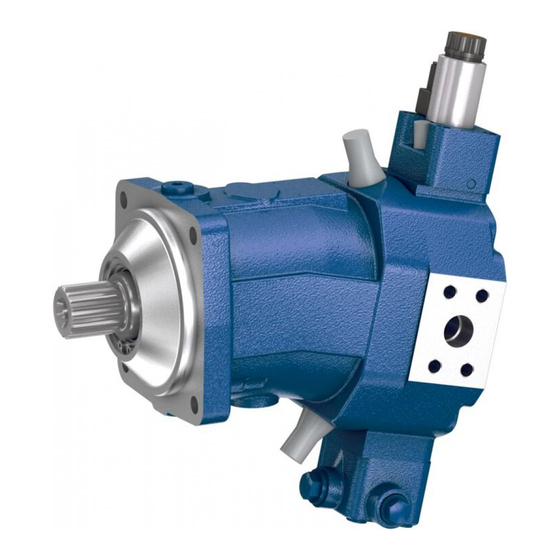
A6VM series 71
Americas
Features
▶ Variable motor with axial tapered piston rotary group of
bent-axis design, for hydrostatic drives in open and
closed circuit
▶ For use in mobile and stationary applications
▶ The wide control range enables the variable motor to
satisfy the requirement for high speed and high torque.
▶ The displacement can be infinitely varied from V
V
= 0.
g min
▶ The output speed is dependent on the flow of the pump
and the displacement of the motor.
▶ The output torque increases with the pressure differen-
tial between the high and low-pressure side and with
increasing displacement.
▶ Wide control range with hydrostatic transmissions
▶ Wide selection of control devices
▶ Cost savings through elimination of gear shifts and
possibility of using smaller pumps
▶ Compact, robust motor with long service life
▶ High power density
▶ Good starting efficiency
▶ Version with 9-piston rotary group
▶ Good low speed characteristics
▶ High uniformity
▶ Sizes 60 to 215
▶ Nominal pressure 6500 psi (450 bar)
▶ Maximum pressure 7250 psi (500 bar)
▶ Open and closed circuits
Contents
to
g max
Dimensions size 115
Dimensions size 150
Dimensions size 170
Dimensions size 215
RE-A 91610
Edition: 12.2015
Replaces: 04.2013
RE-A 91610/12.2015, Bosch Rexroth Corp.
2
5
6
6
7
8
10
13
15
16
17
22
24
25
31
32
38
44
50
56
62
63
65
69
70
72
74
75
Advertisement
Table of Contents

Related Manuals for Bosch Rexroth A6VM series 71


Summary of Contents for Bosch Rexroth A6VM series 71
-
Page 1: Table Of Contents
▶ Version with 9-piston rotary group Connector for solenoids ▶ Good low speed characteristics Flushing and boost pressure valve ▶ High uniformity Counterbalance valve BVD and BVE Speed sensor Setting range for displacement Installation instructions Project planning notes Safety instructions RE-A 91610/12.2015, Bosch Rexroth Corp. -
Page 2: Type Code
(see page 62) Without connector (without solenoid, only for hydraulic control) DEUTSCH - molded connector, 2-pin, without suppressor diode = Available = On request = Not available ● ○ ‒ Connectors for other electric components can deviate. Bosch Rexroth Corp., RE-A 91610/12.2015... - Page 3 ‒ 165-4 ‒ ‒ ‒ ‒ ‒ ● = Available = On request = Not available ● ○ ‒ The settings for the setting screws can be found in the table (see pages 70 and 71). RE-A 91610/12.2015, Bosch Rexroth Corp.
- Page 4 State ordering code for counterbalance valve separately in accor- sheet 95132 for DSM or 95133 for DSA and note the requirements dance with data sheet 95522 for BVD or 95525 for BVE. Note the relating to the electronics. restrictions described on page 65. Bosch Rexroth Corp., RE-A 91610/12.2015...
-
Page 5: Axial Piston Variable Motor | A6Vm Series 71
Range of optimum operating viscosity ν Optimum efficiency (10) Minimum permissible viscosity for short-term operation (−40) (−25) (−10) (0) (10) (30) (50) (70) (90) (115) −40 −13 Minimum permissible temperature for cold start Temperature θ [°F (°C)] RE-A 91610/12.2015, Bosch Rexroth Corp. -
Page 6: Flow Direction
Direction of rotation, viewed on drive shaft from -13 °F to +240 °F (-25 °C to +115 °C). For application clockwise (cw) counter-clockwise (ccw) cases below -13 °F (-25 °C), an NBR shaft seal is required A to B B to A (permissible temperature range: -40 °F to +195 °F (-40 °C to +90 °C)). Bosch Rexroth Corp., RE-A 91610/12.2015... -
Page 7: Operating Pressure Range
Operating pressure range valid when using hydraulic fluids based on mineral oils. Values for other hydraulic fluids, please contact us. Minimum pressure (high-pressure side) Time t Total operating period = t + ... + t RE-A 91610/12.2015, Bosch Rexroth Corp. -
Page 8: Technical Data
Note inlet flow limitation due to counterbalance valve (see page 65). (lower than the maximum angular acceleration) can be Torque without radial force, With radial force see page 9. found in data sheet 90261. Values in this range on request Bosch Rexroth Corp., RE-A 91610/12.2015... - Page 9 ▶ Special requirements apply in the case of belt drives. Please contact us. ▼ Toothed gear output drive 1 Direction of rotation "counter-clockwise", pressure at port B 2 Direction of rotation "clockwise", pressure at port A 3 Bidirectional direction of rotation With intermittent operation RE-A 91610/12.2015, Bosch Rexroth Corp.
-
Page 10: Hp - Proportional Hydraulic Control
> pilot pressure). The control is to be suitably configured to avoid an independent build-up of pilot 290 (20) pressure. 220 (15) 175 (12) 145 (10) 75 (5) 30 (2) g min g max g max Displacement Bosch Rexroth Corp., RE-A 91610/12.2015... - Page 11 1000 (70) 870 (60) 725 (50) 580 (40) 510 (35) 435 (30) 290 (20) 145 (10) 75 (5) g min g max g max Displacement ▼ Circuit diagram HP1, HP2 (positive control) g min g max RE-A 91610/12.2015, Bosch Rexroth Corp.
- Page 12 With the increase in displacement the motor develops more torque, while the pressure remains constant. Setting range of the pressure control valve 1150 to 6500 psi (80 to 450 bar) ▼ Circuit diagram HP5D1, HP6D1 (negative control) g min g max Bosch Rexroth Corp., RE-A 91610/12.2015...
-
Page 13: Ep - Proportional Electric Control
< 435 psi (30 bar), an auxiliary pressure of at least 435 psi (30 bar) must be applied at port G using an external check valve. For lower pressures, please contact us. Please note that pressures up to 7250 psi (500 bar) can occur at port G. RE-A 91610/12.2015, Bosch Rexroth Corp. - Page 14 Setting range of the pressure control valve 1150 to 6500 psi (80 to 450 bar) ▼ Circuit diagram EP5D1, EP6D1 (negative control) ▼ Circuit diagram EP5, EP6 (negative control) g min g max g min g max Bosch Rexroth Corp., RE-A 91610/12.2015...
-
Page 15: Hz - Two-Point Hydraulic Control
G via an external check valve. For lower pressures, please contact us. Please note that pressures up to 7250 psi (500 bar) can occur at port G. ▼ Circuit diagram HZ7 (negative control) size 60 to 115 g min g max RE-A 91610/12.2015, Bosch Rexroth Corp. -
Page 16: Ez - Two-Point Electric Control
Nominal resistance (at 68 °F (20 °C)) 5.5 Ω 21.7 Ω Nominal power 26.2 W 26.5 W g min Minimum required active current 1.32 A 0.67 A g max Duty cycle 100 % 100 % Type of protection: see connector version on page 62 Bosch Rexroth Corp., RE-A 91610/12.2015... -
Page 17: Ha - Automatic High-Pressure Related Control
▶ The beginning of control and the HA.T3 characteristic curve are influenced by case pressure. An increase in case pressure causes an increase in the beginning of control (see page 6) and thus a parallel shift of the characteristic. RE-A 91610/12.2015, Bosch Rexroth Corp. - Page 18 725 (50) 1150 (80) 725 (50) g min g max g max Displacement g min g max g max Displacement ▼ Circuit diagram HA1 ▼ Circuit diagram HA2 g min g max g min g max Bosch Rexroth Corp., RE-A 91610/12.2015...
- Page 19 Pilot pressure at port X 0 psi 145 psi g min 0 bar (10 bar) g max Beginning of control at 4350 psi 1900 psi (300 bar) (130 bar) Note Maximum permissible pilot pressure 1450 psi (100 bar). ▼ Circuit diagram HA1.T3 g min g max RE-A 91610/12.2015, Bosch Rexroth Corp.
- Page 20 Nominal power 30 W 30 W Minimum required active current 1.5 A 0.75 A Duty cycle 100 % 100 % Type of protection: see connector version on page 62 ▼ Circuit diagram HA1U1, HA1U2 g min g max Bosch Rexroth Corp., RE-A 91610/12.2015...
- Page 21 Nominal resistance (at 68 °F (20 °C)) 5.5 Ω 21.7 Ω Nominal power 26.2 W 26.5 W Minimum required active current 1.32 A 0.67 A Duty cycle 100 % 100 % Type of protection: see connector version on page 62 RE-A 91610/12.2015, Bosch Rexroth Corp.
-
Page 22: Da - Automatic Speed-Related Control
We recommend that all DA applications be reviewed by a Bosch Rexroth application engineer. g min... - Page 23 Nominal resistance (at 68 °F (20 °C)) 5.5 Ω 21.7 Ω Nominal power 26.2 W 26.5 W Minimum required active current 1.32 A 0.67 A Duty cycle 100 % 100 % Type of protection: see connector version on page 62 RE-A 91610/12.2015, Bosch Rexroth Corp.
-
Page 24: Electric Travel Direction Valve (For Da, Ha.r)
K1. 1 Switching solenoid a on the travel direction valve K2. 1 K1.2 24 V DC Solenoid a Motor The diodes and relays shown are not included in the scope of delivery of the motor. Bosch Rexroth Corp., RE-A 91610/12.2015... -
Page 25: Dimensions Size 60
0.79 (20) 3.58 (91) 5.16 (131) 4.51 (114.5) 9.29 (236) 5.75 (146) 10.51 (267) View Y 0.94 (23.8) Flange SAEJ744 Center of gravity Port plate 1 — SAE working ports A and B at rear RE-A 91610/12.2015, Bosch Rexroth Corp. - Page 26 S7 ‒ 1 1/4 in 14T 12/24DP 1.89 (48) 1.10 (28) 0.37 (9.5) 1.57 (40) 2.20 (56) Involute toothing acc. to ANSI B92.1a, 30° pressure angle, flat root, side fit, tolerance class 5 Thread according to ASME B1.1 Bosch Rexroth Corp., RE-A 91610/12.2015...
- Page 27 The spot face can be deeper than as specified in the standard. Depending on installation position, T or T must be connected O = Must be connected (plugged on delivery) (see also installation instructions on page 72). X = Plugged (in normal operation) RE-A 91610/12.2015, Bosch Rexroth Corp.
- Page 28 10.35 (263) 1.40 10.39 (264) (35.5) 9.21 (234) 7.24 (184) 1.40 (35.5) ▼ HP5D1, HP6D1 – Hydraulic proportional control, negative control, with pressure control, fixed setting 10.39 (264) 1.40 (35.5) 9.41 (239) Bosch Rexroth Corp., RE-A 91610/12.2015...
- Page 29 HA1T and HA2T, X open ▼ HA1R1, HA2R2 – Automatic high-pressure-related control, positive control, with override, electric and travel direction valve, electric 10.35 (263) 4.33 (110) Port plate 1 – SAE working ports A and B at rear RE-A 91610/12.2015, Bosch Rexroth Corp.
- Page 30 V switch g max 10.51 (267) 10.51 (267) 4.33 0.33 6.30 (160) 7.95 (202) (110) (8.5) 8.90 (226) pipe fitting SDSC – L8×M12 – F according to ISO 8434-1 Use assembled fitting! Bosch Rexroth Corp., RE-A 91610/12.2015...
-
Page 31: Dimensions Size 85
0.91 (23) 3.94 (100) 5.67 (144) 10.35 (263) 7.13 (181) 8.39 (213) 11.61 (295) View Y 1.09 (27.8) Flange SAEJ744 Center of gravity Port plate 1 — SAE working ports A and B at rear RE-A 91610/12.2015, Bosch Rexroth Corp. -
Page 32: Dimensions Size 85
3.94 (100) 5.79 (147) 0.0047 10.35 (263) (0.12) 11.61 (295) 4.51 (114.5) 6.14 (156) View Y 1.09 (27.8) Flange SAEJ744 Center of gravity Port plate 1 — SAE working ports A and B at rear Bosch Rexroth Corp., RE-A 91610/12.2015... - Page 33 S9 ‒ 1 1/2 in 17T 12/24DP 2.13 (54) 1.10 (28) 0.37 (9.5) 1.73 (44) 2.44 (62) Involute toothing acc. to ANSI B92.1a, 30° pressure angle, flat root, side fit, tolerance class 5 Thread according to ASME B1.1 RE-A 91610/12.2015, Bosch Rexroth Corp.
- Page 34 The spot face can be deeper than as specified in the standard. Depending on installation position, T or T must be connected O = Must be connected (plugged on delivery) (see also installation instructions on page 72). X = Plugged (in normal operation) Bosch Rexroth Corp., RE-A 91610/12.2015...
- Page 35 1.40 11.50 (292) 11.42 (290) (35.5) 10.31 (262) 8. 1 5 (207) 1.40 (35.5) ▼ HP5D1, HP6D1 – Hydraulic proportional control, negative control, with pressure control, fixed setting 1.40 11.50 (292) (35.5) 10.51 (267) RE-A 91610/12.2015, Bosch Rexroth Corp.
- Page 36 HA1T and HA2T, X open ▼ HA1R1, HA2R2 – Automatic high-pressure-related control, positive control, with override, electric and travel direction valve, electric 10.35 (263) 4.33 (110) Port plate 1 – SAE working ports A and B at rear Bosch Rexroth Corp., RE-A 91610/12.2015...
- Page 37 V switch g max 11.61 (295) 11.57 (294) 6.30 (160) 9.09 (231) 4.33 0.33 (110) (8.5) 10 (254) pipe fitting SDSC – L8×M12 – F according to ISO 8434-1 Use assembled fitting! RE-A 91610/12.2015, Bosch Rexroth Corp.
-
Page 38: Dimensions Size 115
0.98 (25) 4.33 (110) 5.12 (130) 6.36 (161.6) 11.38 (289) 7.87 (200) 12.68 (322) View Y 1.09 (27.8) Flange SAEJ744 Center of gravity Port plate 1 — SAE working ports A and B at rear Bosch Rexroth Corp., RE-A 91610/12.2015... - Page 39 T1 ‒ 1 3/4 in 13T 8/16 DP 2.64 (67) 1.42 (36) 0.47 (12) 2.17 (55) 2.95 (75) Involute toothing acc. to ANSI B92.1a, 30° pressure angle, flat root, side fit, tolerance class 5 Thread according to ASME B1.1 RE-A 91610/12.2015, Bosch Rexroth Corp.
- Page 40 The spot face can be deeper than as specified in the standard. Depending on installation position, T or T must be connected O = Must be connected (plugged on delivery) (see also installation instructions on page 72). X = Plugged (in normal operation) Bosch Rexroth Corp., RE-A 91610/12.2015...
- Page 41 12.32 (313) 1.59 12.60 (320) (40.5) 11.38 (289) 1.59 9.09 (231) (40.5) ▼ HP5D1, HP6D1 – Hydraulic proportional control, negative control, with pressure control, fixed setting 13.90 (353) 1.59 (40.5) 12.68 (322) RE-A 91610/12.2015, Bosch Rexroth Corp.
- Page 42 HA1T and HA2T, X open ▼ HA1R1, HA2R2 – Automatic high-pressure-related control, positive control, with override, electric and travel direction valve, electric 12.32 (313) 4.41 (112) ports A and B at rear Port plate 1 – SAE working Bosch Rexroth Corp., RE-A 91610/12.2015...
- Page 43 V switch g max 12.68 (322) 4.41 0.33 12.68 (322) 6.85 (174) 9.76 (248) (112) (8.5) 10.63 (270) pipe fitting SDSC – L8×M12 – F according to ISO 8434-1 Use assembled fitting! RE-A 91610/12.2015, Bosch Rexroth Corp.
-
Page 44: Dimensions Size 150
0.98 (25) 4.88 (124) 6.57 (167) 6.36 (161.6) 12.60 (320) 7.87 (200) 13.90 (353) View Y 1.25 (31.8) Flange SAEJ744 Center of gravity Port plate 1 — SAE working ports A and B at rear Bosch Rexroth Corp., RE-A 91610/12.2015... - Page 45 T1 ‒ 1 3/4 in 13T 8/16DP 2.64 (67) 1.42 (36) 0.47 (12) 2.17 (55) 2.95 (75) Involute toothing acc. to ANSI B92.1a, 30° pressure angle, flat root, side fit, tolerance class 5 Thread according to ASME B1.1 RE-A 91610/12.2015, Bosch Rexroth Corp.
- Page 46 The spot face can be deeper than as specified in the standard. Depending on installation position, T or T must be connected O = Must be connected (plugged on delivery) (see also installation instructions on page 72). X = Plugged (in normal operation) Bosch Rexroth Corp., RE-A 91610/12.2015...
- Page 47 13.66 (347) 1.59 13.86 (352) (40.5) 12.64 (321) 1.59 10. 1 2 (257) (40.5) ▼ HP5D1, HP6D1 – Hydraulic proportional control, negative control, with pressure control, fixed setting 1.59 13.90 (353) (40.5) 12.68 (322) RE-A 91610/12.2015, Bosch Rexroth Corp.
- Page 48 10. 1 2 (257) (40.5) HA1 and HA2, X plugged HA1T and HA2T, X open ▼ HA1R1, HA2R2 – Automatic high-pressure-related control, positive control, with override, electric and travel direction valve, electric 13.66 (347) 4.41 (112) Bosch Rexroth Corp., RE-A 91610/12.2015...
- Page 49 V switch g max 6.85 (174) 13.94 (354) 13.94 (354) 4.41 0.33 10.98 (279) 11.89 (302) (112) (8.5) pipe fitting SDSC – L8×M12 – F according to ISO 8434-1 Use assembled fitting! RE-A 91610/12.2015, Bosch Rexroth Corp.
- Page 50 0.98 (25) 4.92 (125) 6.69 (170) 6.36 (161.6) 12.87 (327) 7.87 (200) 14.17 (360) View Y 1.25 (31.8) Flange SAEJ744 Center of gravity Port plate 1 — SAE working ports A and B at rear Bosch Rexroth Corp., RE-A 91610/12.2015...
- Page 51 T2 ‒ 2 in 15T 8/16DP 2.64 (67) 1.42 (36) 0.47 (12) 2.17 (55) 2.95 (75) Involute toothing acc. to ANSI B92.1a, 30° pressure angle, flat root, side fit, tolerance class 5 Thread according to ASME B1.1 RE-A 91610/12.2015, Bosch Rexroth Corp.
- Page 52 The spot face can be deeper than as specified in the standard. Depending on installation position, T or T must be connected O = Must be connected (plugged on delivery) (see also installation instructions on page 72). X = Plugged (in normal operation) Bosch Rexroth Corp., RE-A 91610/12.2015...
- Page 53 13.94 (354) 1.59 14.09 (358) (40.5) 12.91 (328) 1.59 10.39 (264) (40.5) ▼ HP5D1, HP6D1 – Hydraulic proportional control, negative control, with pressure control, fixed setting 1.59 14. 1 7 (360) (40.5) 12.95 (329) RE-A 91610/12.2015, Bosch Rexroth Corp.
- Page 54 1.59 10.39 (264) (40.5) HA1 and HA2, X plugged HA1T and HA2T, X open ▼ HA1R1, HA2R2 – Automatic high-pressure-related control, positive control, with override, electric and travel direction valve, electric 13.94 (354) 4.41 (112) Bosch Rexroth Corp., RE-A 91610/12.2015...
- Page 55 14. 1 7 (360) 4.41 0.33 14. 1 7 (360) 6.85 (174) 11.26 (286) (112) (8.5) 12. 1 7 (309) pipe fitting SDSC – L8×M12 – F according to ISO 8434-1 Use assembled fitting! RE-A 91610/12.2015, Bosch Rexroth Corp.
-
Page 56: Dimensions Size 215
1.26 (32) 5.04 (128) 8.84 (224.5) 6.50 (165) 10.31 (262) 13.62 (346) 14.84 (377) View Y 1.25 (31.8) Flange SAEJ744 Center of gravity Port plate 1 — SAE working ports A and B at rear Bosch Rexroth Corp., RE-A 91610/12.2015... -
Page 57: Dimensions Size 215
T2 ‒ 2 in 15T 8/16DP 2.64 (67) 1.42 (36) 0.47 (12) 2.09 (53) 2.95 (75) Involute toothing acc. to ANSI B92.1a, 30° pressure angle, flat root, side fit, tolerance class 5 Thread according to ASME B1.1 RE-A 91610/12.2015, Bosch Rexroth Corp. - Page 58 The spot face can be deeper than as specified in the standard. Depending on installation position, T or T must be connected O = Must be connected (plugged on delivery) (see also installation instructions on page 72). X = Plugged (in normal operation) Bosch Rexroth Corp., RE-A 91610/12.2015...
-
Page 59: Dimensions Size 215
14.76 (375) 14.61 (371) 1.59 (40.5) 13.54 (344) 1.59 10.91 (277) (40.5) ▼ HP5D1, HP6D1 – Hydraulic proportional control, negative control, with pressure control, fixed setting 1.59 14.80 (376) (40.5) 13.58 (345) RE-A 91610/12.2015, Bosch Rexroth Corp. - Page 60 1.59 10.91 (277) (40.5) HA1 and HA2, X plugged HA1T and HA2T, X open ▼ HA1R1, HA2R2 – Automatic high-pressure-related control, positive control, with override, electric and travel direction valve, electric 14.61 (371) 4.41 (112) Bosch Rexroth Corp., RE-A 91610/12.2015...
- Page 61 V switch g max 14.84 (377) 14.84 (377) 4.41 0.33 6.85 (174) 11.93 (303) (112) (8.5) 12.83 (326) pipe fitting SDSC – L8×M12 – F according to ISO 8434-1 Use assembled fitting! RE-A 91610/12.2015, Bosch Rexroth Corp.
-
Page 62: Connector For Solenoids
2 sockets 0462-201-16141 The mating connector is not included in the scope of deliv- ery. This can be supplied by Bosch Rexroth on request (material number R902601804). Note ▶ If necessary, you can change the position of the con- nector by turning the solenoid. -
Page 63: Flushing And Boost Pressure Valve
S be connected in order to R902138235 0.12 (3.1) 5.5 (21) prevent an increase in case pressure. An increased R909435172 0.14 (3.5) 7.1 (27) R909436622 0.16 (4.0) 8.2 (31) case pressure reduces the flushing flow. RE-A 91610/12.2015, Bosch Rexroth Corp. - Page 64 (381) (295) (172) (148) (244) (201) (217) HP1, HP2 EP5, EP6 EP1, EP2 7/8-14UNF-2B; 0.67 (17) deep 12.76 (324) ISO 11926, ports plugged (in normal operation) The spot face can be deeper than as specified in the standard. Bosch Rexroth Corp., RE-A 91610/12.2015...
-
Page 65: Counterbalance Valve Bvd And Bve
The screws to be used and the procedure mountings can be ports. If the counterbalance valve and motor are delivered found in the instruction manual. separately, the counterbalance valve must first be mounted Pressure-relief valve Counterbalance valve, double-acting Counterbalance valve, single-acting RE-A 91610/12.2015, Bosch Rexroth Corp. - Page 66 ▼ Example schematic for winch drive in cranes A6VM085HP5D10001A/71AWV0C2S97W0-0 + BVE25W38S/51ND-V100K00D4599T30S00-0 Pump, directional Variable motor Counterbalance valve, not included in A6VM...HP5D valve BVE the scope of delivery G´ D´ g min g max C´ Winch with L´ mechanical holding brake Bosch Rexroth Corp., RE-A 91610/12.2015...
- Page 67 The spot face can be deeper than as specified in the standard. The designation of the ports on the installation drawing of the mo- O = Must be connected (plugged on delivery) tor is binding! X = Plugged (in normal operation) RE-A 91610/12.2015, Bosch Rexroth Corp.
- Page 68 The final mounting of the counterbalance valve on the motor is done with screw fitting of the SAE flange. The screws to be used and the procedure mounting can be found in the instruction manual. Bosch Rexroth Corp., RE-A 91610/12.2015...
-
Page 69: Speed Sensor
(18.4) (18.4) (18.4) (18.4) (18.4) (18.4) -0.0098 (-0.25)) B Contact surface 2.95 3.11 3.46 3.66 3.78 3.98 (75) (79) (88) (93) (96) (101) 3.55 3.91 4.30 4.85 4.87 5.01 (90.2) (99.2) (109.2) (123.7) (123.7) (127.2) RE-A 91610/12.2015, Bosch Rexroth Corp. -
Page 70: Setting Range For Displacement
Theoretical, maximum setting: ▶ for V = 0.7 × V g min g max ▶ for V = 0.3 × V g max g max Settings that are not listed in the table may lead to damage. Please contact us. Bosch Rexroth Corp., RE-A 91610/12.2015... - Page 71 Theoretical, maximum setting: ▶ for V = 0.7 × V g min g max ▶ for V = 0.3 × V g max g max Settings that are not listed in the table may lead to damage. Please contact us. RE-A 91610/12.2015, Bosch Rexroth Corp.
-
Page 72: Installation Instructions
Bearing flushing / air bleed port Filling / air bleeding Drain port Minimum required immersion depth (7.87 inch (200 mm)) t min Minimum required distance to tank base (3.94 inch (100 mm)) t min Bosch Rexroth Corp., RE-A 91610/12.2015... - Page 73 Air bleed Filling U (F) t min t min t min t min Note Port F is not part of the motor and can be provided by the customer to make filling and air bleeding easier. RE-A 91610/12.2015, Bosch Rexroth Corp.
-
Page 74: Project Planning Notes
(pressure, volume flow, hydraulic fluid, responding instruction manual completely and thor- temperature) with the required safety factors. oughly. If necessary, these can be requested from Bosch – The service and function ports are only designed to Rexroth. accommodate hydraulic lines ▶... -
Page 75: Safety Instructions
The machine manufacturer / system manufacturer is to undertake additional measures, up to and including encapsulation. RE-A 91610/12.2015, Bosch Rexroth Corp. - Page 76 © This document, as well as the data, specifications and other information set Mobile Applications forth in it, are the exclusive property of Bosch Rexroth Corporation. It may not 8 Southchase Court be reproduced or given to third parties without its consent. The data specified Fountain Inn, SC 29644-9018, USA above only serve to describe the product.
Need help?
Do you have a question about the Rexroth A6VM series 71 and is the answer not in the manual?
Questions and answers