Table of Contents
Advertisement
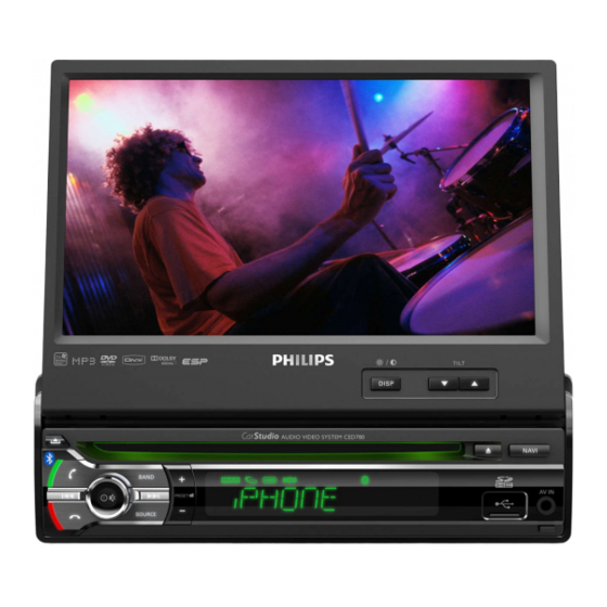
Car Entertainment System
SPECIFICATIONS...............................................................................1-1
CIRCUIT DIAGRAM MAIN&MCU&TUNER BOARD...........................5-8
CIRCUIT DIAGRAM SERVO BOARD.................................................9
CIRCUIT DIAGRAM PANEL& BT BOARD........................................10-11
CIRCUIT DIAGRAM PANEL TFT & SD BOARD...............................12-13
Published by JOEY_SL WK1211
BG LE Printed in The Netherlands Subject to modification
Version 1.2
MAIN & MCU PCB COMPONENT LAYOUT...................................14-15
SERVO PCB COMPONENT LAYOUT.............................................16-17
PANEL&BT PCB COMPONENT LAYOUT.......................................18-19
PANEL TFT&SD PCB COMPONENT LAYOUT...............................20-21
SET EXPLODER VIEW DRAWING.................................................22
TROUBLE SHOOTING ...................................................................23
CED780
/51/55/98/05
314178536642
Advertisement
Table of Contents

Related Manuals for Philips CED780/51


Summary of Contents for Philips CED780/51
-
Page 1: Table Of Contents
CED780 Car Entertainment System /51/55/98/05 MAIN & MCU PCB COMPONENT LAYOUT........14-15 SPECIFICATIONS................1-1 SERVO PCB COMPONENT LAYOUT..........16-17 PANEL&BT PCB COMPONENT LAYOUT........18-19 PANEL TFT&SD PCB COMPONENT LAYOUT.......20-21 CIRCUIT DIAGRAM MAIN&MCU&TUNER BOARD......5-8 SET EXPLODER VIEW DRAWING..........22 CIRCUIT DIAGRAM SERVO BOARD..........9 TROUBLE SHOOTING ..............23 CIRCUIT DIAGRAM PANEL&... -
Page 2: Specifications
1 - 1 SPECIFICATIONS General Power supply 12 V DC (11 V - 16 V), Screen size 7.0 inches negative ground Display resolution 800 x 480 dots Fuse 15 A Contrast ratio length: 128 bytes) Suitable speaker 4 - 8 Brightness 450 cd/m2 impedance... - Page 3 CED780 Dismantlement Method 1. Take out the three screws at heat sink, the six screws at the left right side of the main unit and the screw at the base panel 2. Prize up the left right hook of the base panel and take out the base panel, separate the bottom cover from the unit 3.
-
Page 4: Front Panel
BLOCK DIAGRAM CED780(B) Block Diagram --S3C2451 & CS4728 Solution USB Host IPHONE Subwoofer Deck (Chu Dong) 4558 output I²S or S/PDIF Pickup Sanyo 860 4558 Front Rear Cirrus (SUNPLUS SPHE8202G) Audio output CS47048 (100 pin ) Motor Driver Power Amplifier 16 Pin 5888 SDRAM... - Page 5 WIRING DIAGRAM...
-
Page 6: Circuit Diagram Main&Mcu&Tuner Board
CIRCUIT DIAGRAM-MAIN & MCU & TUNER BOARD... -
Page 10: Circuit Diagram Servo Board
CIRCUIT DIAGRAM-SERVO BOARD... -
Page 11: Circuit Diagram Panel& Bt Board
CIRCUIT DIAGRAM-PANEL & BT BOARD... -
Page 13: Circuit Diagram Panel Tft & Sd Board
CIRCUIT DIAGRAM-PANEL TFT & SD BOARD SD CARD (GPS) VDD_3.3V 3.3VD V_DAC B221 DC+5V FB15 22U/10V CS4334 DEVICE 11 GND R167 R168 ADIN OUTL GPS_AUDIO SDDAT2 10 GND ABLCK USB-SOCKET-MINI DEM/BCK SDDAT3 ALRCIN FL_OUT USB_CHK LRCK NCD_SD 9 D2 33R x 4 AXDI MCLK WP_SD... - Page 14 +12V VDD18 VD_18D VD_33A VDD33 B221 FB14 B600 FB11 B600 L8 3.3uH 22uH DC+5V VLED+ PNL_V/Y B5819WS C117 C114 C139 C118 C119 22UH/1A2 6.8uH 220U/16V 100K 22U/10V 22U/10V 330P 330P 5 OVP RT8284N C112 10U/0805 SYNC 22U/10V BRT/PWM VLED- VD_33D 22U/10V 22U/10V 100U/10V...
-
Page 15: Main & Mcu Pcb Component Layout
PCB LAYOUT-MAIN BOARD TOP SIDE VIEW PCB LAYOUT-MCU BOARD TOP SIDE VIEW... - Page 16 PCB LAYOUT-MAIN BOARD BOTTOM SIDE VIEW PCB LAYOUT-MCU BOARD BOTTOM SIDE VIEW...
-
Page 17: Servo Pcb Component Layout
PCB LAYOUT-SERVO BOARD TOP SIDE VIEW... - Page 18 PCB LAYOUT-SERVO BOARD BOTTOM SIDE VIEW...
-
Page 19: Panel&Bt Pcb Component Layout
PCB LAYOUT-PANEL BOARD TOP SIDE VIEW PCB LAYOUT-PANEL BT BOARD TOP SIDE VIEW... - Page 20 PCB LAYOUT- PANEL BOARD BOTTOM SIDE VIEW PCB LAYOUT- PANEL BT BOARD BOTTOM SIDE VIEW...
-
Page 21: Panel Tft&Sd Pcb Component Layout
PCB LAYOUT-PANEL TFT BOARD TOP SIDE VIEW PCB LAYOUT-PANEL SD BOARD TOP SIDE VIEW... - Page 22 PCB LAYOUT-PANEL TFT BOARD BOTTOM SIDE VIEW PCB LAYOUT- PANEL SD BOARD BOTTOM SIDE VIEW...
-
Page 23: Set Exploder View Drawing
SET EXPLODER VIEW DRAWING 440-0C352499-00-00... -
Page 24: Trouble Shooting
Product Model CED780 Tate 2011-11-28 failure failure cause remark phenomena a. To check whether the CN2(14pin) connector of the tail of the unit is connect well , Whether it is loose of the 15A fuse of the Filter Box, or insert non in place. b. - Page 25 failure failure cause remark phenomena a. To check whether the signal format of the disc is correspond to the request of the unit, whether there is any contamination or damage or light leakage on the surface of the disc. b. To check whether there is any abnormal of the rotation of the deck mechanism, or whether the disc is enter in position.
Need help?
Do you have a question about the CED780/51 and is the answer not in the manual?
Questions and answers