Table of Contents
Advertisement
Advertisement
Table of Contents

Related Manuals for Zynex Medical NexWave


Summary of Contents for Zynex Medical NexWave
- Page 1 NexWave User’s Manual...
-
Page 3: Table Of Contents
NexWave Table of Contents Contact Information / Customer Service / Supplies / Support About the NexWave Safety Information Electrodes and Lead Wires Setup Programming Instructions Preprogrammed Modes Controls Operating Instructions Protocols Indications, Contraindications and Warnings Precautions and Adverse Reactions Troubleshooting Specifications and Accessories... -
Page 4: Contact Information
Durable Medical Equipment (DME) or questions about an Explanation of Benefits form you received in the mail FAX NUMBER 800-495-6695 303-347-9153 MAILING ADDRESS Zynex Medical, Inc. 9555 Maroon Circle Englewood, CO 80112 EMAIL info@zynex.com WEBSITE www.zynex.com EUROPEAN REPRESENTATIVE... -
Page 5: About The Nexwave
About the NexWave The NexWave is a multiple-mode stimulator which allows users a choice of treatment options. This device incorporates Interferential Current (IFC), Transcutaneous Electrical Nerve Stimulation (TENS), and Neuromuscular Electrical Stimulation (NMES). Interferential Current (IFC) The left channel (channel 1) produces a signal at a frequency of 4000 Hz. A slightly higher frequency (4001-4128 Hz) is produced by the right channel (channel 2). -
Page 6: Safety Information
The NexWave a Class IIa medical device per the European Medical Device Directive. Internally Powered Equipment When the NexWave is powered by the internal, 9 VDC, MN1604, battery it is classified as Internally Powered Equipment. Class II Medical Equipment When powered by the external, 12 VDC, medical grade, power supply, the NexWave is classified as Class II Medical Electrical (ME) Equipment. - Page 7 Safety Information Mode of Operation This device is suitable for continuous operation. Symbols Safety symbols shown on this device above are defined below. On/Off. This symbol indicates that the labeled switch electronically cycles the DC power on and off for part of the equipment. Note: To disconnect the external power supply, unplug the power cord of the supplied AC adapter from the AC mains outlet.
- Page 8 Waste Electrical and Electronic Equipment (WEEE). This product may contain substances known to be hazardous to the environment or to human health. It should be disposed of properly (for example, at your local waste collection administration or recycling plant) and in accordance with local ordinances.
-
Page 9: Electrodes And Lead Wires Setup
Open electrode package and remove electrodes from package. Keep electrodes on plastic backing. Note: Only Zynex Medical electrodes are approved for use with the NexWave. P/N 300027 are provided standard. Sterile electrodes, P/N 300100, are optionally available (for U.S. only). See additional accessories on page 43. - Page 10 NexWave Electrode and Lead Wire Setup (continued) Step 3 Remove each electrode from the plastic backing and place on the treatment site according to the type of modality selected. Electrode Arrangement When using the IFC modality, and BLACK lead wires must be placed in a crisscrossed pattern as shown in the diagram below.
- Page 11 NexWave Electrode and Lead Wire Setup (continued) Step 4 Plug lead wires into the top of this device. The IFC modality requires both lead wires to be connected (channel 1 & 2). TENS and NMES can use 1 (Channel 1) or 2 (Channel 1 & 2) lead wires.
-
Page 12: Programming Instructions
NexWave Device Programming Instructions Place electrodes on the skin prior to turning on this device. Turn device on by pressing the black On/Off button Select desired Modality by pressing the “IFC”, “TENS”, or “NMES” button once. Continue to press the selected modality button until arrow is next to desired program. -
Page 13: Preprogrammed Modes
NexWave Preprogrammed Modes Interferential Current (IFC) Mode Description Low-High The frequency of channel 2 sweeps between 4001 Hz and 4128 Hz every 15 seconds, while the channel 1 frequency remains fixed at 4000 Hz. The frequency of channel 2 sweeps between 4001 Hz and 4010 Hz every 15 seconds, while the channel 1 frequency remains fixed at 4000 Hz. - Page 14 NexWave Preprogrammed Modes Neuromuscular Electrical Stimulation (NMES) Mode Description 30:10 Preset 10 seconds on and 30 seconds off time, 35 Hz frequency, 480 μs pulse width, 3 second ramp-up, 1 second ramp-down, both channels cycle simultaneously. 20:10 Same as above, but with a 20 second off time.
-
Page 15: Controls
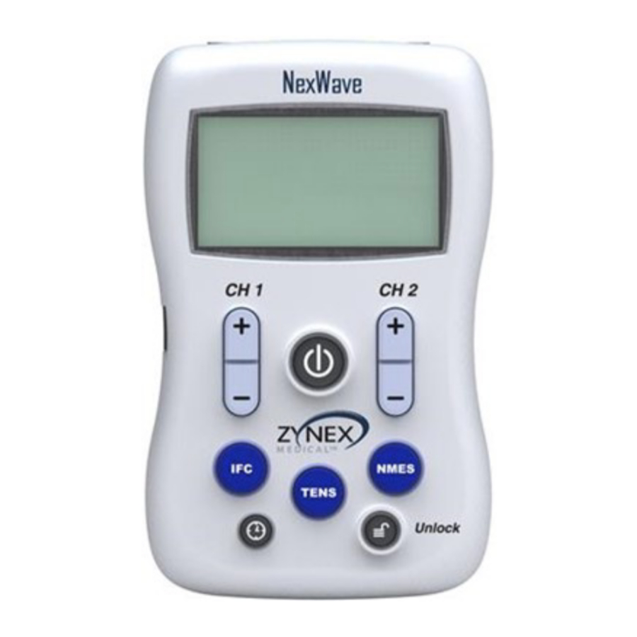
NexWave Device Controls Display Lead Wire Connection Lead Wire Connection Channel 1 Channel 2 Uses electricity from wall socket instead of 9 V battery A/C Adapter Input Turns Unit On/Off On/Off Button Channel 2 Intensity Control Channel 1 Intensity Control... -
Page 16: Operating Instructions
Before starting treatment electrodes must be placed on the treatment site and lead wires and electrodes connected to this device. See pages 9-11 and 17-31 for examples. Turn NexWave on by pressing On/Off button once. Increase intensity by pressing Channel 1 Up button until a strong but comfortable stimulation level is felt. - Page 17 Radicular Back Pain-Sciatica PAIN CONTROL - TENS ONLY INTENSITY LEVEL: The stimulation level should be set to a strong, but comfortable strength. DEVICE SET-UP: Modality Mode Suggested Treatment ________________________________________________________________________________________________________________________________________________________________________ TENS Swp, Lmd, Hmd As needed ELECTRODE PLACEMENT Place one set of electrodes for one channel close to the spine and follow the pain route as shown below.
- Page 18 Lumbar Back PAIN CONTROL INTENSITY LEVEL: The stimulation level should be set to a strong, but comfortable strength. DEVICE SET-UP: Modality Mode Treatment Time ________________________________________________________________________________________________________________________________________________________________________ LoHi, Low, Cmb 40 minutes 4 times/day TENS Swp, Lmd, Hmd As needed ELECTRODE PLACEMENT Electrodes should surround the targeted treatment site with area of pain located in the center of the electrode area.
- Page 19 Cervical / Upper Back PAIN CONTROL INTENSITY LEVEL: The stimulation level should be set to a strong, but comfortable strength. DEVICE SET-UP: Modality Mode Treatment Time ________________________________________________________________________________________________________________________________________________________________________ LoHi, Low, Cmb 40 minutes 4 times/day TENS Swp, Lmd, Hmd As needed ELECTRODE PLACEMENT Electrodes should surround the targeted treatment site with area of pain located in the center of the electrode area.
- Page 20 Thoracic Back PAIN CONTROL INTENSITY LEVEL: The stimulation level should be set to a strong, but comfortable strength. DEVICE SET-UP: Modality Mode Treatment Time _______________________________________________________________________________________________________________________________________________________________________ LoHi, Low, Cmb 40 minutes 4 times/day TENS Swp, Lmd, Hmd As needed ELECTRODE PLACEMENT Electrodes should surround the targeted treatment site with area of pain located in the center of the electrode area.
- Page 21 Shoulder PAIN CONTROL INTENSITY LEVEL: The stimulation level should be set to a strong, but comfortable strength. DEVICE SET-UP: Modality Mode Treatment Time ________________________________________________________________________________________________________________________________________________________________________ LoHi, Low, Cmb 40 minutes 4 times/day TENS Swp, Lmd, Hmd As needed ELECTRODE PLACEMENT Electrodes should surround the targeted treatment site with area of pain located in the center of the electrode area.
- Page 22 Elbow PAIN CONTROL INTENSITY LEVEL: The stimulation level should be set to a strong, but comfortable strength. DEVICE SET-UP: Modality Mode Treatment Time _______________________________________________________________________________________________________________________________________________________________________ LoHi, Low, Cmb 40 minutes 4 times/day TENS Swp, Lmd, Hmd As needed ELECTRODE PLACEMENT Electrodes should surround the targeted treatment site with area of pain located in the center of the electrode area.
- Page 23 Wrist PAIN CONTROL INTENSITY LEVEL: The stimulation level should be set to a strong, but comfortable strength. DEVICE SET-UP: Modality Mode Treatment Time ________________________________________________________________________________________________________________________________________________________________________ LoHi, Low, Cmb 40 minutes 4 times/day TENS Swp, Lmd, Hmd As needed ELECTRODE PLACEMENT Electrodes should surround the targeted treatment site with area of pain located in the center of the electrode area.
- Page 24 PAIN CONTROL INTENSITY LEVEL: The stimulation level should be set to a strong, but comfortable strength. DEVICE SET-UP: Modality Mode Treatment Time ________________________________________________________________________________________________________________________________________________________________________ LoHi, Low, Cmb 40 minutes 4 times/day TENS Swp, Lmd, Hmd As needed ELECTRODE PLACEMENT Electrodes should surround the targeted treatment site with area of pain located in the center of the electrode area.
- Page 25 Back of Leg PAIN CONTROL INTENSITY LEVEL: The stimulation level should be set to a strong, but comfortable strength. DEVICE SET-UP: Modality Mode Treatment Time ________________________________________________________________________________________________________________________________________________________________________ LoHi, Low, Cmb 40 minutes 4 times/day TENS Swp, Lmd, Hmd As needed ELECTRODE PLACEMENT Electrodes should surround the targeted treatment site with area of pain located in the center of the electrode area.
- Page 26 Anterior Knee PAIN CONTROL INTENSITY LEVEL: The stimulation level should be set to a strong, but comfortable strength. DEVICE SET-UP: Modality Mode Treatment Time ________________________________________________________________________________________________________________________________________________________________________ LoHi, Low, Cmb 40 minutes 4 times/day TENS Swp, Lmd, Hmd As needed ELECTRODE PLACEMENT Electrodes should surround the targeted treatment site with area of pain located in the center of the electrode area.
- Page 27 Lateral / Medial Knee PAIN CONTROL INTENSITY LEVEL: The stimulation level should be set to a strong, but comfortable strength. DEVICE SET-UP: Modality Mode Treatment Time ________________________________________________________________________________________________________________________________________________________________________ LoHi, Low, Cmb 40 minutes 4 times/day TENS Swp, Lmd, Hmd As needed ELECTRODE PLACEMENT Electrodes should surround the targeted treatment site with area of pain located in the center of the electrode area.
- Page 28 Ankle PAIN CONTROL INTENSITY LEVEL: The stimulation level should be set to a strong, but comfortable strength. DEVICE SET-UP: Modality Mode Treatment Time ________________________________________________________________________________________________________________________________________________________________________ LoHi, Low, Cmb 40 minutes 4 times/day TENS Swp, Lmd, Hmd As needed ELECTRODE PLACEMENT Electrodes should surround the targeted treatment site with area of pain located in the center of the electrode area.
- Page 29 Foot PAIN CONTROL INTENSITY LEVEL: The stimulation level should be set to a strong, but comfortable strength. DEVICE SET-UP: Modality Mode Treatment Time ________________________________________________________________________________________________________________________________________________________________________ LoHi, Low, Cmb 40 minutes 4 times/day TENS Swp, Lmd, Hmd As needed ELECTRODE PLACEMENT Electrodes should surround the targeted treatment site with area of pain located in the center of the electrode area.
-
Page 30: Protocols
Post-Operative Knee PAIN RELIEF & EDEMA REDUCTION Post-operative pain and swelling may be reduced by the application of electrical stimulation immediately after surgery and continuing as needed. INTENSITY LEVEL: The stimulation level should be set to a strong, but comfortable strength. DEVICE SET-UP: Modality Mode... - Page 31 Muscle Spasm SPASM REDUCTION Muscle spasm may be reduced by intentionally fatiguing the associated muscle or muscle group. INTENSITY LEVEL: The stimulation level should be set to a strong, but comfortable strength. DEVICE SET-UP: Modality Mode Treatment Time ________________________________________________________________________________________________________________________________________________________________________ 40 minutes 3 to 4 times/day NMES 10:10 on: off...
- Page 32 Using the supplied AC adapter to power the unit, the maximum peak voltage that the NexWave can produce is 50 V (1000 Ω load). The maximum peak current that the NexWave can produce is 50 mA (1000 Ω load). The maximum output power that the NexWave can produce is 2.5 W per channel...
- Page 33 NexWave Warnings Interferential Current (IFC) Warnings (Continued) Maximum peak output voltage (500 Ω load) = 25 V Maximum peak output current (500 Ω load) = 50 mA Maximum peak output voltage (1 KΩ load) = 50 V ...
- Page 34 Safety References Zynex Medical, Inc. is only responsible for the safety, reliability and function of this device when repairs and adjustments have been made by persons authorized by Zynex Medical, Inc., and this device is used in accordance with the user’s manual.
- Page 35 The maximum peak voltage that the NexWave can produce is 100 V (1000 Ω load). The maximum peak current that the NexWave can produce is 100 mA (1000 Ω load). The maximum output power that the NexWave can produce...
- Page 36 NexWave Warnings Transcutaneous Electrical Nerve Stimulation (TENS) Warnings (Continued) Maximum peak output voltage (500 Ω load) = 50 V Maximum peak output current (500 Ω load) = 100 mA Maximum peak output voltage (1 KΩ load) = 100 V ...
- Page 37 Safety References Zynex Medical, Inc. is only responsible for the safety, reliability and function of this device when repairs and adjustments have been made by persons authorized by Zynex Medical, Inc., and this device is used in accordance with the user’s manual.
- Page 38 Therefore its output voltage, current, and power are dependent upon the load as well as the pulse width and frequency of the output waveform. The maximum peak voltage that the NexWave can produce is 100 V (1000 Ω load).
- Page 39 Warnings Neuromuscular Electrical Stimulation (NMES) Warnings (Continued) The maximum output power that the NexWave can produce is 0.168 W per channel into a 1000 Ω load, 0.336 W total. Maximum peak output voltage (500 Ω load) = 50 V ...
- Page 40 Safety References Zynex Medical, Inc. is only responsible for the safety, reliability and function of this device when repairs and adjustments have been made by persons authorized by Zynex Medical, Inc., and this device is used in accordance with the user’s manual.
-
Page 41: Precautions And Adverse Reactions
NexWave Precautions and Adverse Reactions All Modes (IFC, TENS, NMES) Precautions Isolated cases of skin irritation may occur at the site of the electrode placement following long-term application. Effectiveness is highly dependent upon patient selection by a person qualified in management of pain patients. -
Page 42: Troubleshooting
When the ON button is Press and hold the UNLOCK button for 20 seconds or pressed, a flashing “Lock” until the “Lock” icon on the display disappears. icon appears on the display and the NexWave remains unresponsive. -
Page 43: Specifications And Accessories
NexWave Specifications and Accessories Interferential Current (IFC) Amplitude: 0-50 mA Channel 1 frequency: 4000 Hz Channel 2 frequency: 4001- 4128 Hz I/F Modes: Low-High, Low, Combo Muscle Mode: 64 Hz, 6 sec. on, 6 sec. off, ramp up 1 sec., and ramp down 0.5 sec. - Page 44 Please dispose of used batteries properly. AC Adapter The NexWave is supplied with an AC adapter that is plugged into the left side of this device and then into a 120 or 230 VAC electrical outlet. Note: The supplied AC adapter, Zynex P/N 200109, mains power requirement is 100-240 VAC, 50-60 Hz, 0.3A...
-
Page 45: Warranty
five years after the original purchase. During that time, Zynex Medical, Inc. will repair or replace, at its sole discretion, the NexWave device that has been used in a standard manner. This warranty does not cover misuse or use contrary to the operating instructions supplied. - Page 48 Zynex Medical, Inc. 9555 Maroon Circle Englewood, CO 80112 Phone: 1-800-495-6670 Fax: 1-800-495-6695 Internet: www.zynex.com Email: info@zynex.com European Representative: Zynex Europe Fælledvej 1, Box 19 BDO DK-5100 Odense C Denmark P/N 300400, Rev. 10, 12/8/2017...
Need help?
Do you have a question about the NexWave and is the answer not in the manual?
Questions and answers
Batteries don't last long at all with Zynex unit Maybe 2 hours
The batteries of the Zynex Medical NexWave unit only last about 2 hours because rechargeable batteries are not recommended due to their short usage time and inability to charge while in the device. The device uses a 9V alkaline battery, which has limited capacity when powering the unit for multiple treatments daily.
This answer is automatically generated