Advertisement
Service
Manual
AUDIO SYSTEM
HEAD UNIT
VEHICLE
DESTINATION
LEXUS RX330
U.S.A.
CANADA
Manufactured for TOYOTA
by PIONEER CORPORATION
RX330
PRODUCED AFTER
TOYOTA PART No.
February 2003
86120-48180
86120-48320
86120-48190
86120-48330
ORDER NO.
CRT3022
ID No.
PIONEER MODEL No.
P6826
FX-MG8227ZT/UC
P6826
FX-MG8227ZT-91/UC
P6827
FX-MG8327ZT/UC
P6827
FX-MG8327ZT-91/UC
CRT3022
PUB. NO.
Advertisement
Table of Contents

Related Manuals for Pioneer FX-MG8227ZT-91/UC


Summary of Contents for Pioneer FX-MG8227ZT-91/UC
- Page 1 Service Manual ORDER NO. CRT3022 RX330 AUDIO SYSTEM HEAD UNIT VEHICLE DESTINATION PRODUCED AFTER TOYOTA PART No. ID No. PIONEER MODEL No. LEXUS RX330 U.S.A. February 2003 86120-48180 P6826 FX-MG8227ZT/UC CANADA 86120-48320 P6826 FX-MG8227ZT-91/UC 86120-48190 P6827 FX-MG8327ZT/UC 86120-48330 P6827 FX-MG8327ZT-91/UC...
- Page 2 For details, refer to "Important symbols for good services". FX-MG8227ZT/UC(P6826) FX-MG8327ZT/UC(P6827) - This service manual should be used together with the following manual(s): Model No. Order No. Mech. Module Remarks CX-1011 CRT2406 Cassette Mech. Module:Mech.Description, Disassembly CX-951 CRT2872 CD Mech. Module:Circuit Description, Mech.Description, Disassembly - Dolby noise reduction manufactured under license from Dolby Laboratories Licensing Corporation.
-
Page 3: Block Diagram And Schematic Diagram
3. BLOCK DIAGRAM AND SCHEMATIC DIAGRAM 3.1 BLOCK DIAGRAM(1) PU UNIT(SERVICE)(PX1) PCB UNIT PCB UNIT(SIDE) CN11 CN12 CN41 MD 23 A+C,B+D, HOLOGRAM UNIT FOCUS ACT TRACKING ACT PCB UNIT(M2 UNIT) MOTOR CN42 DRIVER SPINDLE SIN(EC) IC 1 BA6849FS S2 CLAMP CLAMP CLAMP S1 HOME... - Page 4 3.2 BLOCK DIAGRAM(2) FM/AM TUNER UNIT FM/AM 1ST IF 10.7MHz MPXREF 41kHz AMRF T51 Q51 CF51 CF52 CF53 AMDET AMANT L ch IC 2 FM MPX R ch Q406 AMIN CN501 ANT ADJ COMP MAIN ANTENNA MIXER, IF AMP, DET. LDET FMANT ANTENNA...
-
Page 5: Main Unit
BALANCE TO UNBALANCE CONVERTER LANLP IC201 MAIN UNIT LANL LANLM NJM2068MD TUNER SELECTOR MIXING AMP UNBALANCE TO BALANCE CONVERTER IC401 NJM2068MD Q203 Q204 sysmute@ IC203 IC204 IC202 Q406 Q202 NJM2068MD NJM2068MD TC4052BF SEL1b Q201 Q205 SEL1a SELECTOR UNBALANCE TO BALANCE CONVERTER Q303 Q304 sysmute... -
Page 6: Overall Connection Diagram(Guide Page)
3.3 OVERALL CONNECTION DIAGRAM(GUIDE PAGE) Note: When ordering service parts, be sure to refer to " EXPLODED VIEWS AND PARTS LIST" or "ELECTRICAL PARTS LIST". Large size SCH diagram FM(30%,400Hz)(FX-MG8227ZT/UC):-24.3dBs FX-MG8227ZT/UC FX-MG8327ZT/ AM(30%,400Hz)(FX-MG8227ZT/UC):-11.8dBs FM/AM TUNER UNIT R417 FM(30%,400Hz)(FX-MG8327ZT/UC):-24.5dBs R418 AM(30%,400Hz)(FX-MG8327ZT/UC):-11.7dBs C411 R018 ANTENNA... - Page 7 NOTE : Symbol indicates a resistor. FX-MG8327ZT/UC Decimal points for resistor No differentiation is made between chip resistors and and capacitor fixed values discrete resistors. are expressed as : R018 BALANCE TO UNBALANCE ← Symbol indicates a capacitor. R018 ← No differentiation is made between chip capacitors and 0.022 R022...
- Page 8 FX-MG8227ZT/UC...
- Page 9 FX-MG8227ZT/UC...
- Page 10 FX-MG8227ZT/UC...
- Page 11 FX-MG8227ZT/UC...
-
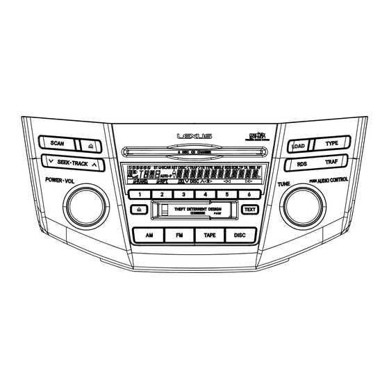
Page 12: Keyboard Unit
3.4 KEYBOARD UNIT KEYBOARD PCB LEFT PCB POWER•VOL SCAN SEEK•TRACK DOWN TAPE EJECT TEXT CD EJECT LOAD SEEK•TRACK DISC TAPE CN804 FX-MG8227ZT/UC... -
Page 13: Right Pcb
RIGHT PCB AUDIO CONTROL• TUNE TRAF TYPE 2SC4116 R998 4R7K FX-MG8227ZT/UC... -
Page 14: Cd Mechanism Module(Guide Page)
3.5 CD MECHANISM MODULE(GUIDE PAGE) @) 8 1 PCB UNIT (SIDE) PCB UNIT (M2 UNIT) CN11 ELVSENSE CCW1023 MOTOR DRIVER 1K(B) PCB UNIT CD CONTROL SPINDLE MOTOR LOAD3 CN42 CSN1051 CN12 CSN1057 CLAMP HOME CSN1057 CRG MOTOR M3 CXC1143 CN41 CN14 PU UNIT(SERVICE)(PX1) 3+3ch... - Page 15 CONTROL UNIT(G2T) MUTE 3.3V-5V CONVERTER BUFFER RAM SHOCK PROOF MEMORY CONTROLLER & 5V-3.3V CONVERTER 3.3V REGULATOR 5V REGULATOR MECHANISM CONTROLLER FX-MG8227ZT/UC...
- Page 16 F G H FX-MG8227ZT/UC...
- Page 17 FX-MG8227ZT/UC...
- Page 18 CN351 FX-MG8227ZT/UC...
- Page 19 FX-MG8227ZT/UC...
- Page 20 Note: The encircled numbers denote measuring points in the circuit diagram. CH1 : 1 FDX CH1 : 5 RFO Mode:Test Mode:Test CH2 : 2 FOP CH2 : 6 TE CH3 : 3 FOM CH3 : 7 TEC CH4 : 4 EC Focus search mode Tracking open CH1 : 5 RFO...
- Page 21 CH1 : 6 TE CH1 : 1 FDX Mode:Normal Mode:Normal CH2 : 9 FE CH2 : ! FOK CH3 : 0 RFI CH3 : @ MDX CH4 : # FG Focus close Setup CH1 : 9 FE Mode:Normal CH1 : $ STSMO Mode:Normal CH2 : 1 FDX CH2 : 6 TE...
- Page 22 CH1 : * LOUT CH1 : 6 TE Mode:Normal Mode:Normal CH2 : ( ROUT CH2 : 8 TDX CH3 : ) SD CH4 : 4 EC Audio output(1kHz , 0dB) During inside / outside search CH1 : 1 FDX Mode:Normal CH2 : ! FOK CH3 : @ MDX CH4 : # FG...
-
Page 23: Cassette Mechanism Module
3.6 CASSETTE MECHANISM MODULE DECK UNIT CN252 VR302 CCP1280 Q271 33K(B) 2SC4116 R260 R258 C254 390P Rev-L R284 0R0 R256 C253 390P Rev-R MSGV(R) NFI(L) R283 0R0 R403 MAOUT RIN(L) C271 R287 C404 R01 IC251 Fwd-R R282 0R0 1/50 MSDET FIN(L) C252 390P HA12216F... -
Page 24: Sensor Unit
M1 MOTOR UNIT (MAIN MOTOR) EXA1618 CN255 Q101 CN256 EGN1004 CN253 L102 L101 Q271 2SC4116 R277 R375 70µs S103 220K MODE S102 R373 load LOAD S101 R275 ESG1007x3 C405 R033 SENSOR UNIT R404 270K CN254 MOTOR UNIT (SUB MOTOR) VCC2 EXA1623 R374 MECHANISM... -
Page 25: Connection Diagram
Rear Disp and SDVD GGD1319 RSE ECU M/L AMP SYSTEM cannot use GGD1317. Because, external connector is different from pioneer AMP and VTR Adapter M/L AMP(PIO:24P-20P,M/L:25P-16P). Moreover, GGD1240 which is a previous jig cannot be used (Because the signal array is different). - Page 26 SP Line AUI- AUI+ M/L AMP SYSTEM cannot use GGD1317. Because, external connector is different from pioneer AMP and M/L AMP(PIO:24P-20P,M/L:25P-16P). Moreover, GGD1240 which is a previous jig cannot be used (Because the signal array is different). Therefore, when the head unit of the M/L AMP system is repaired, pioneer AMP system is used.
- Page 27 GGD1319 RSE ECU M/L AMP SYSTEM cannot use GGD1317. VTR Adapter Because, external connector is different from pioneer AMP and M/L AMP(PIO:24P-20P,M/L:25P-16P). Moreover, GGD1240 which is a previous jig cannot be used (Because the signal array is different). Therefore, when the head unit of the M/L AMP system is repaired, pioneer AMP system is used.
- Page 28 SP Line (To DC Regulated Power Supply) M/L AMP SYSTEM cannot use GGD1317. Because, external connector is different from pioneer AMP and M/L AMP(PIO:24P-20P,M/L:25P-16P). Moreover, GGD1240 which is a previous jig cannot be used (Because the signal array is different).
Need help?
Do you have a question about the FX-MG8227ZT-91/UC and is the answer not in the manual?
Questions and answers