Table of Contents
Advertisement
Service
Manual
AUDIO SYSTEM
HEAD UNIT
VEHICLE
DESTINATION
LEXUS LS430
U.S.A.,CANADA August 2000
LEXUS LS430
U.S.A.,CANADA August 2000
LEXUS LS430
EUROPE
LEXUS LS430
OVERSEAS
Manufactured for TOYOTA
by PIONEER CORPORATION
LS430
PRODUCED AFTER
ID No.
P6811
P6815
August 2000
P3902
August 2000
P7801
TOYOTA PART No.
PIONEER MODEL No.
86120-50670
FX-MG9006ZT/UC
FX-MG9006ZT-91/UC
86120-50660
FX-MG9506ZT/UC
FX-MG9506ZT-91/UC
86120-50680
FX-MG9006ZT/EW
FX-MG9006ZT-91/EW
86120-50720
FX-MG9006ZT/ES
FX-MG9006ZT-91/ES
PUB. NO.
ORDER NO.
CRT2539
CRT2539
Advertisement
Table of Contents

Related Manuals for Pioneer FX-MG9006ZT/UC


Summary of Contents for Pioneer FX-MG9006ZT/UC
- Page 1 Service Manual ORDER NO. CRT2539 LS430 AUDIO SYSTEM HEAD UNIT VEHICLE DESTINATION PRODUCED AFTER ID No. TOYOTA PART No. PIONEER MODEL No. LEXUS LS430 U.S.A.,CANADA August 2000 P6811 86120-50670 FX-MG9006ZT/UC FX-MG9006ZT-91/UC LEXUS LS430 U.S.A.,CANADA August 2000 P6815 86120-50660 FX-MG9506ZT/UC FX-MG9506ZT-91/UC...
-
Page 2: Fx-Mg9006Zt,Mg9006Zt-91,Mg9506Zt,Mg9506Zt
ID No. P7801 NOTE: - FX-MG9006ZT-91/UC, FX-MG9506ZT-91/UC, FX-MG9006ZT-91/EW and FX-MG9006ZT-91/ES are supplementary genuine part for a TOYOTA vehicle, and a Pioneer product for recycling stock. - Supplementary model is identical to the original except for the addition of following items. Part No. -
Page 3: Table Of Contents
FX-MG9006ZT,MG9006ZT-91,MG9506ZT,MG9506ZT-91 - This service manual should be used together with the following manual(s): Model Order No. Mech. Module Remarks CX-890 CRT2376 CD Mechanism Module:Circuit Description, Mech.Description, Disassembly CX-631 CRT1640 Cassette Mech. Module:Mech.Description, Disassembly - Dolby noise reduction manufactured under license from Dolby Laboratories Licensing Corporation. "Dolby"... -
Page 4: Safety Information
FX-MG9006ZT,MG9006ZT-91,MG9506ZT,MG9506ZT-91 1. SAFETY INFORMATION This service manual is intended for qualified service technicians; it is not meant for the casual do-it-yourselfer. Qualified technicians have the necessary test equipment and tools, and have been trained to properly and safely repair complex products such as those covered by this manual. Improperly performed repairs can adversely affect the safety and reliability of the product and may void the warranty. -
Page 5: Exploded Views And Parts List
FX-MG9006ZT,MG9006ZT-91,MG9506ZT,MG9506ZT-91 2. EXPLODED VIEWS AND PARTS LIST 2.1 EXTERIOR (FX-MG9006ZT/UC,FX-MG9506ZT/UC) - Page 6 FX-MG9006ZT,MG9006ZT-91,MG9506ZT,MG9506ZT-91...
- Page 7 - Parts marked by “*” are generally unavailable because they are not in our Master Spare Parts List. ∇ mark on the product are used for disassembly. - Screws adjacent to - EXTERIOR SECTION PARTS LIST (FX-MG9006ZT/UC,FX-MG9506ZT/UC) Mark No. Description Part No.
- Page 8 FX-MG9006ZT,MG9006ZT-91,MG9506ZT,MG9506ZT-91 Mark No. Description Part No. 89 Spring CBH2361 90 Spring CBH2365 91 Spring Uint CXB6850 92 Connector CDE6302 93 Chassis CNA2131 94 Holder CNC7477 95 Holder CNC7826 96 Holder CNC8160 97 Holder CNC8161 98 Holder CNC8162 99 Mechanism Assy(Service)CXX1430 100 Sheet CNM5981 101 Insulator...
- Page 9 FX-MG9006ZT,MG9006ZT-91,MG9506ZT,MG9506ZT-91 2.2 EXTERIOR (FX-MG9006ZT/EW)
- Page 10 FX-MG9006ZT,MG9006ZT-91,MG9506ZT,MG9506ZT-91...
- Page 11 FX-MG9006ZT,MG9006ZT-91,MG9506ZT,MG9506ZT-91 - EXTERIOR SECTION PARTS LIST (FX-MG9006ZT/EW) Mark No. Description Part No. Mark No. Description Part No. 1 Screw BMZ26P040FMC 46 Holder CNC8778 2 Screw BMZ26P050FMC 47 Holder CNC8798 3 Screw(#1) BMZ50P080FMC 48 Plate CNM6841 4 Connector CDE6172 49 Rubber CNV5678 5 Case CNB2425...
- Page 12 FX-MG9006ZT,MG9006ZT-91,MG9506ZT,MG9506ZT-91 Mark No. Description Part No. 91 Spring Uint CXB6850 92 Connector CDE6302 93 Chassis CNA2131 94 Holder CNC7477 95 Holder CNC7826 96 Holder CNC8160 97 Holder CNC8161 98 Holder CNC8162 99 Mechanism Assy(Service)CXX1430 100 Sheet CNM5981 101 Insulator CNM7141 102 Sheet CNM6318 103 Insulator...
- Page 13 FX-MG9006ZT,MG9006ZT-91,MG9506ZT,MG9506ZT-91 2.3 EXTERIOR (FX-MG9006ZT/ES)
- Page 14 FX-MG9006ZT,MG9006ZT-91,MG9506ZT,MG9506ZT-91...
- Page 15 FX-MG9006ZT,MG9006ZT-91,MG9506ZT,MG9506ZT-91 - EXTERIOR SECTION PARTS LIST (FX-MG9006ZT/ES) Mark No. Description Part No. Mark No. Description Part No. 1 Screw BMZ26P040FMC 46 Holder CNC8778 2 Screw BMZ26P050FMC 47 Holder CNC8798 3 Screw(#1) BMZ50P080FMC 48 Plate CNM6841 4 Connector CDE6172 49 Rubber CNV5677 5 Case CNB2533...
- Page 16 FX-MG9006ZT,MG9006ZT-91,MG9506ZT,MG9506ZT-91 Mark No. Description Part No. 91 Spring Uint CXB6850 92 Connector CDE6302 93 Chassis CNA2131 94 Holder CNC7477 95 Holder CNC7826 96 Holder CNC8160 97 Holder CNC8161 98 Holder CNC8162 99 Mechanism Assy(Service)CXX1430 100 Sheet CNM5981 101 Insulator CNM7141 102 Sheet CNM6318 103 Insulator...
- Page 17 FX-MG9006ZT,MG9006ZT-91,MG9506ZT,MG9506ZT-91 2.4 CD MECHANISM...
- Page 18 FX-MG9006ZT,MG9006ZT-91,MG9506ZT,MG9506ZT-91 - CD MECHANISM SECTION PARTS LIST Mark No. Description Part No. Mark No. Description Part No. 1-9 ••••• 59 Gear CNC7236 10 CD Core Unit(Servo Unit) CWX2421 60 Gear CNC8883 11 Connector(CN101) CKS2764 61 Lever CNC7243 12 Connector(CN301) CKS3966 62 Lever CNC7244 13 Connector(CN201)
- Page 19 FX-MG9006ZT,MG9006ZT-91,MG9506ZT,MG9506ZT-91 Mark No. Description Part No. Mark No. Description Part No. 109 Screw CBA1041 159 Screw CBA1453 110 Screw CBA1250 160 Washer CBF1038 111 Screw CBA1362 CXX1457 Loading Arm R Assy(Service) 112 Screw CBA1471 162 Washer CBF1074 113 Washer CBF1038 163 Spring CBH2136 114 Spring...
- Page 20 FX-MG9006ZT,MG9006ZT-91,MG9506ZT,MG9506ZT-91 2.5 CASSETTE MECHANISM MODULE...
- Page 21 FX-MG9006ZT,MG9006ZT-91,MG9506ZT,MG9506ZT-91 - CASSETTE MECHANISM MODULE SECTION PARTS LIST Mark No. Description Part No. Mark No. Description Part No. 1 Screw BSZ20P040FMC 31 Gear ENV1347 2 Washer CBF1037 32 Collar ENV1508 3 Washer CBF1038 33 Gear ENV1350 4 Washer CBG1003 34 Flywheel ENV1500 5 Deck Unit EWM1027...
-
Page 22: Block Diagram And Schematic Diagram
FX-MG9006ZT,MG9006ZT-91,MG9506ZT,MG9506ZT-91 3. BLOCK DIAGRAM AND SCHEMATIC DIAGRAM 3.1 BLOCK DIAGRAM (FX-MG9006ZT/UC) CD CORE UNIT(SERVO UNIT) MAIN UNIT PICKUP UNIT(SERVICE) CN101 CD CORE UNIT(STS UNIT) RF AMP 8fs DF D/A LPF CN701 CN701 CN801 CN201 Q301 IC 201 CD MUTE IC 101... - Page 23 FX-MG9006ZT,MG9006ZT-91,MG9506ZT,MG9506ZT-91 ANALOG SW UNBAL → BAL IC305 MIXING Q301 Q307 SYS MUTE TC74HC4066AF CD MUTE TAPE MUTE IC301 IC302 IC303 NJM2068MD NJM2068MD NJM2068MD Q602 Q309 Q303 Q305 Q702 Q603 Q833 Q831 SW5V Q601 ILL+ SW5V ILL- X601 HARD MUTE 10.00MHz MUTE Q801 MUTE...
- Page 24 : -4.8dBs TAPE MUTE TAPE 250nwb/m 315Hz : -7.2dBs : +2.2dBs SCH diagram Guide page CD MUTE Detailed page FX-MG9006ZT/UC : D601,602 FX-MG9006ZT/EW : D601,603 CD 0dB 1kHz : +2.1dBs FX-MG9006ZT/ES : D603,604 CD CONTROLLER PD5575B KEYBOARD UNIT ILL2 SELECTOR...
- Page 25 FX-MG9006ZT,MG9006ZT-91,MG9506ZT,MG9506ZT-91 NOTE : UNBALANCE TO BALANCE CONVERTER Symbol indicates a resistor. Decimal points for resistor No differentiation is made between chip resistors and ANALOG SWITCH and capacitor fixed values discrete resistors. are expressed as : ← Symbol indicates a capacitor. ←...
- Page 26 FX-MG9006ZT,MG9006ZT-91,MG9506ZT,MG9506ZT-91...
- Page 27 FX-MG9006ZT,MG9006ZT-91,MG9506ZT,MG9506ZT-91...
- Page 28 FX-MG9006ZT,MG9006ZT-91,MG9506ZT,MG9506ZT-91...
- Page 29 FX-MG9006ZT,MG9006ZT-91,MG9506ZT,MG9506ZT-91...
- Page 30 FX-MG9006ZT,MG9006ZT-91,MG9506ZT,MG9506ZT-91 3.3 KEYBOARD UNIT, SW UNIT KEYBOARD PCB UC, EW : CAW1591 ES : CAW1582...
- Page 31 FX-MG9006ZT,MG9006ZT-91,MG9506ZT,MG9506ZT-91 KEYBOARD UNIT Consists of KEYBOARD PCB BACKLIGHT PCB S902 S903 S904 S908 S916 S920 TRAF TYPE SCAN P.SCAN FM1/2 SCAN CN804 BACKLIGHT S922 S923 SW UNIT CDEJ LOAD CDEJ LOAD LOAD CDEJ...
- Page 32 FX-MG9006ZT,MG9006ZT-91,MG9506ZT,MG9506ZT-91 3.4 CD CORE UNIT(SERVO UNIT) CD CORE UNIT(SERVO UNIT) RF AMP/ AUTO POWER PICKUP UNIT CONTROL (SERVICE)(P8) CD DRIVER MOTOR PCB(B) M4 CARRIAGE CXB3178 DISC INSERT DETECT M5 SPINDLE CXM1120...
- Page 33 FX-MG9006ZT,MG9006ZT-91,MG9506ZT,MG9506ZT-91 FOCUS/TRACKING CARRIAGE/SPINDLE DIGITAL SERVO DIGITAL SIGNAL PROCESSOR D/A CONVERTER...
- Page 34 FX-MG9006ZT,MG9006ZT-91,MG9506ZT,MG9506ZT-91 3.5 CD CORE UNIT(STS UNIT) CD CORE UNIT(STS UNIT) SURE TRACK MEMORY CONTROLLER +5V REGULATOR M1 : CXB6929 ELV SENSE Q1 : RPI-221 M3 : CXB3175 MOTOR PCB MOTOR DRIVER...
- Page 35 FX-MG9006ZT,MG9006ZT-91,MG9506ZT,MG9506ZT-91 D/A CONVERTER ROLLER 4M DRAM MOTOR DRIVER...
- Page 36 FX-MG9006ZT,MG9006ZT-91,MG9506ZT,MG9506ZT-91 Note:1. The encircled numbers denote measuring pointes in the circuit diagram. 2. Reference voltage REFOUT:2.5V - Waveforms 1 RFO 1 RFO 1 CH1: RFO 0.5V/div. 0.2µs/div. 0.5V/div. 0.5µs/div. 1V/div. 0.5ms/div. 2 CH2: MIRR Normal mode: play Test mode 5V/div. Normal mode: The defect part passes 500µs/div.
- Page 37 FX-MG9006ZT,MG9006ZT-91,MG9506ZT,MG9506ZT-91 3 CH1: FIN 1V/div. 8 CH1: TEY 8 CH1: TEY 0.5V/div. 0.5V/div. 0.2s/div. 5ms/div. 500µs/div. $ CH2: HOLD 6 CH2: FEY ! CH2: SD 5V/div. 0.1V/div. 0.5V/div. µ Normal mode: The defect part passes 800 Normal mode: AGC after focus close REFOUT→...
- Page 38 FX-MG9006ZT,MG9006ZT-91,MG9506ZT,MG9506ZT-91 8 CH1: TEY 8 CH1: TEY 0.5V/div. 0.5V/div. & SCKO 2V/div. 500ns/div. 5ms/div. 10ms/div. 9 CH2: TIN 9 CH2: TIN 0.5V/div. 0.5V/div. Test mode: 100 tracks jump(FWD) Normal mode: Play Play REFOUT→ REFOUT→ REFOUT→ REFOUT→ REFOUT→ ) CH1: RCH 2V/div.
- Page 39 FX-MG9006ZT,MG9006ZT-91,MG9506ZT,MG9506ZT-91 3.6 PCB UNIT(A,B,C,D,E), LOAD MOTOR PCB PCB UNIT(B) PCB UNIT(E) PCB UNIT(C) CPT230SCTD MAX DETECT SWITCH PCB UNIT(A) CN802 CPT230SCTD CXB3177 PCB UNIT(D) S886:CSN1052 S887:CSN1051 LOAD MOTOR PCB...
-
Page 40: Cassette Mechanism Module
FX-MG9006ZT,MG9006ZT-91,MG9506ZT,MG9506ZT-91 3.7 CASSETTE MECHANISM MODULE DECK UNIT CN252 VR302 CCP1280 Q271 33K(B) 2SC4116 R260 R258 C253 390P Rev-L R283 0R0 R275 R256 C254 390P Rev-R MSGV(R) NFI(L) R284 0R0 R403 C405 R033 MAOUT RIN(L) C271 R291 C404 R01 IC251 Fwd-R R282 0R0 R404 1/50... - Page 41 FX-MG9006ZT,MG9006ZT-91,MG9506ZT,MG9506ZT-91 PCB UNIT M1 MOTOR UNIT (MAIN MOTOR) CN253 EXA1499 LOAD R373 load ESG1004 70µs R375 ESG1004 R277 220K R362 R275 MODE SENSE 405 R033 R404 270K EGN1 EGN1005 CN254 MOTOR UNIT (SUB MOTOR) EGN2 EGN3 VCC2 EXA1382 EGN1006 EGN1006 FWD END REV END SENSE...
-
Page 42: Pcb Connection Diagram
FX-MG9006ZT,MG9006ZT-91,MG9506ZT,MG9506ZT-91 4. PCB CONNECTION DIAGRAM MAIN UNIT 4.1 MAIN UNIT NOTE FOR PCB DIAGRAMS 1. The parts mounted on this PCB include all necessary parts for several destination. For further information for respective destinations, be sure to check with the schematic diagram. - Page 43 FX-MG9006ZT,MG9006ZT-91,MG9506ZT,MG9506ZT-91 SIDE A CN701 CN251 FRONT...
- Page 44 FX-MG9006ZT,MG9006ZT-91,MG9506ZT,MG9506ZT-91 MAIN UNIT...
- Page 45 FX-MG9006ZT,MG9006ZT-91,MG9506ZT,MG9506ZT-91 SIDE B...
- Page 46 FX-MG9006ZT,MG9006ZT-91,MG9506ZT,MG9506ZT-91 4.2 KEYBOARD PCB (FX-MG9006ZT/UC, FX-MG9506ZT/UC, FX-MG9006ZT/EW) SIDE A...
- Page 47 FX-MG9006ZT,MG9006ZT-91,MG9506ZT,MG9506ZT-91 SIDE B...
- Page 48 FX-MG9006ZT,MG9006ZT-91,MG9506ZT,MG9506ZT-91 4.3 KEYBOARD PCB (FX-MG9006ZT/ES) SIDE A...
- Page 49 FX-MG9006ZT,MG9006ZT-91,MG9506ZT,MG9506ZT-91 SIDE B...
- Page 50 FX-MG9006ZT,MG9006ZT-91,MG9506ZT,MG9506ZT-91 4.4 BACKLIGHT PCB SIDE B SIDE A CN906...
- Page 51 FX-MG9006ZT,MG9006ZT-91,MG9506ZT,MG9506ZT-91 4.5 SW UNIT SIDE B SIDE A...
- Page 52 FX-MG9006ZT,MG9006ZT-91,MG9506ZT,MG9506ZT-91 4.6 CD CORE UNIT(SERVO UNIT) SIDE A PICKUP UNIT (SERVICE)
- Page 53 FX-MG9006ZT,MG9006ZT-91,MG9506ZT,MG9506ZT-91 SIDE B...
- Page 54 FX-MG9006ZT,MG9006ZT-91,MG9506ZT,MG9506ZT-91 4.7 CD CORE UNIT(STS UNIT) CD CORE UNIT(STS UNIT) SIDE A...
- Page 55 FX-MG9006ZT,MG9006ZT-91,MG9506ZT,MG9506ZT-91 SIDE B CD CORE UNIT(STS UNIT)
- Page 56 FX-MG9006ZT,MG9006ZT-91,MG9506ZT,MG9506ZT-91 4.8 MOTOR PCB(A) SIDE A MOTOR PCB(A) M3 ELV M1 CAM GEAR ELV SENSE CN201...
- Page 57 FX-MG9006ZT,MG9006ZT-91,MG9506ZT,MG9506ZT-91 SIDE B MOTOR PCB(A) CN801...
- Page 58 FX-MG9006ZT,MG9006ZT-91,MG9506ZT,MG9506ZT-91 4.9 MOTOR PCB(B) SPINDLE MOTOR MOTOR PCB(B)
- Page 59 FX-MG9006ZT,MG9006ZT-91,MG9506ZT,MG9506ZT-91 CN301 CARRIAGE...
- Page 60 FX-MG9006ZT,MG9006ZT-91,MG9506ZT,MG9506ZT-91 4.11 PCB UNIT(D) 4.10 PCB UNIT(B) PCB UNIT(B) PCB UNIT(D) CN802 S887 CLAMP S886 ELV HOME...
- Page 61 FX-MG9006ZT,MG9006ZT-91,MG9506ZT,MG9506ZT-91 4.12 PCB UNIT(C) Q881 PCB UNIT(C) S885 MAX DETECT D883...
- Page 62 FX-MG9006ZT,MG9006ZT-91,MG9506ZT,MG9506ZT-91 4.13 LOAD MOTOR PCB LOAD MOTOR PCB LOAD 4.14 PCB UNIT(A) PCB UNIT(A) D892 D891...
- Page 63 FX-MG9006ZT,MG9006ZT-91,MG9506ZT,MG9506ZT-91 4.15 PCB UNIT(E) PCB UNIT(E) PCB UNIT(E) SIDE A SIDE B...
- Page 64 FX-MG9006ZT,MG9006ZT-91,MG9506ZT,MG9506ZT-91 4.16 CASSETTE MECHANISM MODULE SIDE A DECK UNIT IC,Q ADJ C351 C401 C352 VR302 CN254 C354 VR302 Q271 Q271 R351 R355 C403 C404 R291 C402 CN253 R262 R275 R403 R256 R284 CN252 IC351 R274 IC351 R282 R273 R281 IC251 IC251 R272 R283...
- Page 65 FX-MG9006ZT,MG9006ZT-91,MG9506ZT,MG9506ZT-91 PCB UNIT SIDE A LOAD SW 70µs SW MODE SENSE EGN1 PCB UNIT SIDE B 6 5 4 3 2 1 CN253 MOTOR UNIT (MAIN MOTOR) REEL PCB...
-
Page 66: Electrical Parts List
=====Circuit Symbol & No.===Part Name Part No. =====Circuit Symbol & No.===Part Name Part No. ------ ------------------------------------------ ------------------------- ------ ------------------------------------------ ------------------------- Unit Number : CWM6852 Transistor DTA114EK (FX-MG9006ZT/UC) 2SJ517 (FX-MG9506ZT/UC) Transistor DTC123YK : CWM6853 Chip Transistor 2SC2712 (FX-MG9006ZT/EW) Transistor DTC114EK : CWM6857 (FX-MG9006ZT/ES) - Page 67 FX-MG9006ZT,MG9006ZT-91,MG9506ZT,MG9506ZT-91 =====Circuit Symbol & No.===Part Name Part No. =====Circuit Symbol & No.===Part Name Part No. ------ ------------------------------------------ ------------------------- ------ ------------------------------------------ ------------------------- RESISTORS 1kΩ CCN1120 47kΩ CCN1131 RS1/10S102J RS1/10S122J RA2CQ102J RS1/10S122J RA3C102J RS1/10S473J RS1/10S473J 1kΩ CCN1120 RS1/10S123J RS1/10S473J RS1/10S473J RS1/10S123J RS1/10S102J RS1/10S183J RA2CQ473J RS1/10S183J...
- Page 68 FX-MG9006ZT,MG9006ZT-91,MG9506ZT,MG9506ZT-91 =====Circuit Symbol & No.===Part Name Part No. =====Circuit Symbol & No.===Part Name Part No. ------ ------------------------------------------ ------------------------- ------ ------------------------------------------ ------------------------- RS1/8S472J 4.7µF/35V CCH1016 RS1/8S222J 4.7µF/35V CCH1016 RS1/8S472J CCSQCH330J50 RS1/8S221J CCSQCH330J50 RS1/10S473J CKSQYB331K50 RS1/10S104J CKSQYB331K50 RS1/10S473J CKSQYB682K50 RS1/10S104J CKSQYB682K50 RS1/10S473J CKSQYB682K50 RS1/10S104J CKSQYB682K50...
- Page 69 CKSQYB102K50 Keyboard Unit CKSQYB474K16 Consists of Keyboard PCB CKSQYB103K50 Backlight PCB CCSQCH101J50 CCSQCH101J50 Unit Number : CWM6865 (FX-MG9006ZT/UC) Unit Number : CWX2421 (FX-MG9506ZT/UC) Unit Name : CD Core Unit(Servo Unit) (FX-MG9006ZT/EW) : CWM6864 MISCELLANEOUS (FX-MG9006ZT/ES) Unit Name : Keyboard Unit...
- Page 70 FX-MG9006ZT,MG9006ZT-91,MG9506ZT,MG9506ZT-91 =====Circuit Symbol & No.===Part Name Part No. =====Circuit Symbol & No.===Part Name Part No. ------ ------------------------------------------ ------------------------- ------ ------------------------------------------ ------------------------- RESISTORS CKSRYB682K50 CKSRYB333K16 CKSQYB334K16 RS1/8S100J CKSQYB334K16 RS1/8S120J CKSQYB334K16 RS1/16S822J RS1/16S682J CKSQYB334K16 RS1/16S183J CKSQYB104K16 CKSRYB472K50 RS1/16S822J CKSQYB104K16 RS1/16S333J CCSRCH5R0C50 RS1/16S683J RS1/16S134J CKSRYB153K25 RS1/16S273J...
- Page 71 FX-MG9006ZT,MG9006ZT-91,MG9506ZT,MG9506ZT-91 =====Circuit Symbol & No.===Part Name Part No. =====Circuit Symbol & No.===Part Name Part No. ------ ------------------------------------------ ------------------------- ------ ------------------------------------------ ------------------------- RS1/16S102J Unit Number : RS1/16S102J Unit Name : Motor PCB(B) RS1/16S102J RS1/16S471J Motor Unit(Carriage) CXB3178 RS1/16S101J Motor(Spindle) CXM1120 RS1/16S101J Unit Number : RS1/16S471J Unit Name...
- Page 72 FX-MG9006ZT,MG9006ZT-91,MG9506ZT,MG9506ZT-91 =====Circuit Symbol & No.===Part Name Part No. =====Circuit Symbol & No.===Part Name Part No. ------ ------------------------------------------ ------------------------- ------ ------------------------------------------ ------------------------- RS1/8S0R0J Unit Number : RS1/8S0R0J Unit Name : Reel PCB RS1/8S0R0J RS1/8S0R0J Photo-Interrupter EGN1006 RS1/8S0R0J Photo-Interrupter EGN1006 RS1/8S0R0J Miscellaneous Parts List RS1/8S0R0J RS1/8S0R0J Pickup Unit(Service)(P8)
-
Page 73: Adjustment
FX-MG9006ZT,M9006ZT-91,M9506ZT,M9506ZT-91 6. ADJUSTMENT - CONNECTION DIAGRAM Hide Away TUNER DECK UNIT GEX-T9006ZT/UC VR302 VR301 Pin2 GGD1121 Pin3 To MAIN UNIT (CN301) CN251 L-CH R-CH Meter GGD1232 BULLET CONNECTOR DSP AMP GM-9006ZT/E Rear Controller CD-R1976ZT/E GGD1169 BULLET CONNECTOR 6.1 AUDIO ADJUSTMENT DOLBY NR ADJUSTMENT Test Tape Adjustment Point... -
Page 74: Checking The Grating After Changing The Pickup Unit
FX-MG9006ZT,M9006ZT-91,M9506ZT,M9506ZT-91 6.2 CHECKING THE GRATING AFTER CHANGING THE PICKUP UNIT • Note : The grating angle of the PU unit cannot be adjusted after the PU unit is changed. The PU unit in the CD mechanism module is adjusted on the production line to match the CD mechanism module and is thus the best adjusted PU unit for the CD mechanism module. - Page 75 FX-MG9006ZT,M9006ZT-91,M9506ZT,M9506ZT-91 Ech → Xch 20mV/div, AC Grating waveform Fch → Ych 20mV/div, AC 0° 30° 45° 60° 75° 90°...
-
Page 76: General Information
FX-MG9006ZT,M9006ZT-91,M9506ZT,M9506ZT-91 7. GENERAL INFORMATION 7.1 DIAGNOSIS 7.1.1 TEST MODE - CD Test Mode 1) Precautions on Adjustment 2) Description of the Test Mode • The unit employs a single voltage (+5V) for the • Turning on the Test Mode regulator, thus the reference potential of the signal is See page 77. - Page 77 FX-MG9006ZT,M9006ZT-91,M9506ZT,M9506ZT-91 - CD Player Flow Chart [Key] [1] + [6] + [DISC] 3 times Diag. Mode In Contents Display [TRACK UP] + [AM] Test Mode In PBUS TEST EW model ES model [MSG] [ASL] [P.SCAN] [DISC] 3sec [TYPE] [PTY] [ASL] Diag.
- Page 78 FX-MG9006ZT,M9006ZT-91,M9506ZT,M9506ZT-91 - CD Mechanism Test Mode Flow Chart [Key] [1] + [6] + [DISC] 3 times Diag. Mode In Contents Display [TRACK UP] + [AM] Test Mode In PBUS TEST EW model ES model [DISC] 3sec [MSG] [ASL] [P.SCAN] Diag. off [TYPE] [PTY] [ASL]...
- Page 79 FX-MG9006ZT,M9006ZT-91,M9506ZT,M9506ZT-91 Operating Procedures for Ejecting a Clamped Disc Select CAMMOTOR using [3], then press the [TRACK DOWN] while the disc is being clamped (CAMSW state is 32). The CAMSW status indication sequentially changes through 32→33→23→22. When the disc to be ejected is not identical with the disc being clamped, select the [4 ] ELVMOTOR in the vicinity of where the display changes from 22 to 20, then match the elevation to the disc to be ejected according to the following procedures: After selecting ELVMOTOR, lower the elevation until the ELV position display becomes 01 (1st disc) using the [TRACK DOWN].
- Page 80 FX-MG9006ZT,M9006ZT-91,M9506ZT,M9506ZT-91 Code Name Description Door OPENING While the mechanism is in operation, should have been closed a door was opened. Roller OFF time-out 4 seconds have elapsed before completing the roller OFF (the cam gear has not been rotated to the roller-OFF end position). Roller SET time-out 4 seconds have elapsed before completing the roller SET.
-
Page 81: Self-Diagnostic Function
FX-MG9006ZT,M9006ZT-91,M9506ZT,M9506ZT-91 7.1.2 SELF-DIAGNOSTIC FUNCTION Audio System Service Test Operation procedures Purpose of operation Procedure How to enter service Press the "Disc" (or "CD") button three times with the ch "1" and "6" buttons of the H/U test mode (Head Unit) pressed at the same time. (When the service test mode is switched, a beep sound is output. - Page 82 FX-MG9006ZT,M9006ZT-91,M9506ZT,M9506ZT-91 1. Transition of "service test mode" display Physical address P190 Self diagnosis Diagnostic memory TUNE DOWN TUNE UP Display of results (OK) good TUNE DOWN TUNE UP Physical address P360 System test result request Diagnostic memory request TUNE DOWN TUNE UP Display of results (Check) "Test"...
- Page 83 FX-MG9006ZT,M9006ZT-91,M9506ZT,M9506ZT-91 2. Transition of "Test detailed information display mode" or "Exchange detailed information display mode" display • If the ch "2" button is pressed when "CHEC" (test) or "ECHn" (exchange) is displayed, each detailed information display mode is entered. • To switch from each detailed information display mode to the "service test mode", press the ch "3" button. •...
- Page 84 FX-MG9006ZT,M9006ZT-91,M9506ZT,M9506ZT-91 - "Exchange" detailed information screen Connecting equipment: Radio cassette (PA = 190), CD - CH (PA = 360), MD - CH (PA = 3A0) * If memory clear is executed in the P360 detailed information display mode, a diagnostic memory clear instruction is individually send to object equipment Service test mode and the service test mode is switched.
- Page 85 FX-MG9006ZT,M9006ZT-91,M9506ZT,M9506ZT-91 - "Test" detailed information display screen Connecting equipment: Radio cassette (PA = 190), CD - CH (PA = 360), MD - CH (PA = 3A0) * If memory clear is executed in the P3A0 detailed information display mode, a Service test mode diagnostic memory clear instruction is individually send to object equipment and...
- Page 86 FX-MG9006ZT,M9006ZT-91,M9506ZT,M9506ZT-91 - "Old Ver" detailed information display screen Connecting equipment: Radio cassette (PA = 190), CD - CH (PA = 360), MD - CH (PA = 3A0) * If memory clear is executed in the P3A0 detailed information display mode, a Service test mode diagnostic memory clear instruction is individually send to object equipment and...
-
Page 87: Disassembly
FX-MG9006ZT,M9006ZT-91,M9506ZT,M9506ZT-91 7.1.3 DISASSEMBLY Case Removing the Case (Fig.1) Remove the six screws and then remove the Holder. Remove the two screws and then remove the Case. Holder Fig.1 Cassette Mechanism Module Removing the Grille Assy (Fig.2) Remove the two screws and then remove the Grille Assy. - Page 88 FX-MG9006ZT,M9006ZT-91,M9506ZT,M9506ZT-91 Removing the Chassis Unit (Fig.4) Remove the seven screws and then remove the Chassis Unit. Fig.4 Chassis Unit - Removing the Mechanism Assy (Fig.5) 1. Disconnect the Connector. 2. Remove the three screws A, and then remove the Holder and Damper. 3.
- Page 89 FX-MG9006ZT,M9006ZT-91,M9506ZT,M9506ZT-91 - How to remove the Tray Assy 3. Lift up the Tray assy to remove it. 1. Apply about 6V current to the Cam gear motor until * Be careful not to remove the Tray hooks from the Tray all holes match at the position (A) (elevation OK assy.
- Page 90 FX-MG9006ZT,M9006ZT-91,M9506ZT,M9506ZT-91 10. Remove the screw, pressure spring and collar. Lift up the Carriage mechanism assy to remove it. Screw * Screw tightening torque: 2.6kgfcm Pressure spring Collar Carriage mechanism Assy Fig.9 - How to remove the Pickup unit 1. Remove the pulling spring, torsion spring and E- Pulling spring shaped ring.
- Page 91 FX-MG9006ZT,M9006ZT-91,M9506ZT,M9506ZT-91 8. Loosen the 2 screws. Remove the plate spring and the rack. Grease (Yellow: 9. Pull out the feed screw from the Pickup unit. PG-641) Plate spring Rack Feed screw Grease (White: KD-1) Grease (Yellow: PG-641) Pickup unit Fig.12...
-
Page 92: Pcb Locations
FX-MG9006ZT,M9006ZT-91,M9506ZT,M9506ZT-91 7.1.4 PCB LOCATIONS MAIN UNIT KEYBOARD PCB BACKLIGHT PCB SW UNIT MOTOR PCB(B) MOTOR PCB(A) PCB UNIT(B) CD CORE UNIT(SERVO UNIT) CD CORE UNIT(STS UNIT) LOAD MOTOR PCB PCB UNIT(D) PCB UNIT(A) PCB UNIT(E) PCB UNIT PCB UNIT(C) REEL PCB DECK UNIT... -
Page 93: Connector Function Description
FX-MG9006ZT,M9006ZT-91,M9506ZT,M9506ZT-91 7.1.5 CONNECTOR FUNCTION DESCRIPTION - FX-MG9006ZT/UC, FX-MG9506ZT/UC, FX-MG9006ZT/ES MUTE TXS+ SGND ILL+ ILL- TXS- - FX-MG9006ZT/EW MUTE SGND TXS+ SGND MUTE ILL+ ILL- TXM+ TXM- GND TXS-... -
Page 94: Parts
FX-MG9006ZT,M9006ZT-91,M9506ZT,M9506ZT-91 7.2 PARTS 7.2.1 IC - Pin Functions (PD5556B) Pin No. Pin Name Function and Operation LOFF LCD driver OFF output Not used BLIGHT Not used LAMP power supply control LCD driver data output Not used Clock output for LCD driver BYTE VCC joint CNVSS... - Page 95 FX-MG9006ZT,M9006ZT-91,M9506ZT,M9506ZT-91 Pin No. Pin Name Function and Operation Key strobe output kst$ KST3 Key strobe output kst@ Key strobe output kst! Key strobe output Key strobe output kst) Music sense input Head forward/reverse select output PLAY MS gain select output Cassette mechanism tape select input CDEJ CD eject key sense input...
- Page 96 FX-MG9006ZT,M9006ZT-91,M9506ZT,M9506ZT-91 - Pin Functions (PD5575B) Pin No. Pin Name Format Function and Operation VDIN Power supply short sensor input doorsw Door open position SW input Not used P-BUS service request output bsrq clamp DISC clamp SW input elhome ELV reset position SW input XSCK CD LSI clock output CD LSI data output...
- Page 97 FX-MG9006ZT,M9006ZT-91,M9506ZT,M9506ZT-91 Pin No. Pin Name Format Function and Operation Not used VREF A/D converter reference voltage input AVSS A/D GND ADRMON The remainder amount address monitor input EREF DRAM A/D reference voltage Disc photo sense input 1 Disc photo sense input 2 Disc photo sense input 3 ELVSNS ELV position photo sense input...
- Page 98 FX-MG9006ZT,M9006ZT-91,M9506ZT,M9506ZT-91 HA12216F NFI(L) MSGV(R) Dolby B-N RIN(L) MAOUT FIN(L) MSDET MSOUT FIN(R) MSGV VREF RIN(R) 120/70 Dolby B-N NFI(R)
-
Page 99: Display
FX-MG9006ZT,M9006ZT-91,M9506ZT,M9506ZT-91 7.2.2 DISPLAY - CAW1591 (FX-MG9006ZT/UC, FX-MG9506ZT/UC, FX-MG9006ZT/EW) - Page 100 FX-MG9006ZT,M9006ZT-91,M9506ZT,M9506ZT-91 - CAW1582 (FX-MG9006ZT/ES)
-
Page 101: System Block Diagram
FX-MG9006ZT,M9006ZT-91,M9506ZT,M9506ZT-91 7.3 SYSTEM BLOCK DIAGRAM POWER SUPPLY(+B, ACC) - (7SP) SIGNAL(SOUND, VISION) GM-9006ZT/E FX-MG9006ZT/UC FX-MG9006ZT/EW FX-MG9106ZT/EW FX-MG9006ZT/ES FX-MG9106ZT/ES FX-MG9506ZT/UC CHANGER (OTHER MAKERS) (EW model only) RADIO +B, ACC TUNER GEX-T9006ZT/UC GEX-T9006ZT/EW GEX-T9006ZT/ES GEX-T9106ZT/ES CD-R1976ZT/E - (7SP+REAR CONTROLLER) REAR CONTROLLER FX-MG9006ZT/UC... -
Page 102: Operational Flow Chart
FX-MG9006ZT,M9006ZT-91,M9506ZT,M9506ZT-91 7.4 OPERATIONAL FLOW CHART Power ON VDD=5V 16pin, 62pin bsens 20pin asens 19pin IPPW 22pin Starts communication with AVC-LAN. swvdd 45pin brst 36pin Starts communication with G1 microcomputer. Source Keys operative Source ON Completes power-on operation. (After that, proceed to each source operation.) -
Page 103: Operations And Specifications
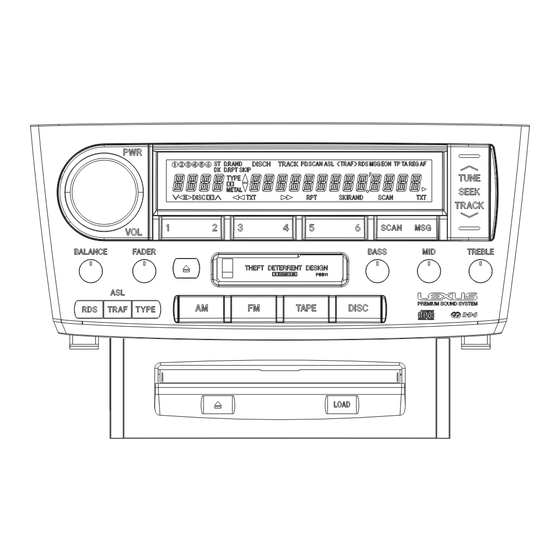
FX-MG9006ZT,M9006ZT-91,M9506ZT,M9506ZT-91 8. OPERATIONS AND SPECIFICATIONS 8.1 OPERATIONS (FX-MG9006ZT/UC) - RADIO PRESET RECALL POWER ON/OFF PRESET CH. MEMORY SCAN VOLUME DOWN MANUAL TUNING SEEK TUNING BASS TREBLE TRAFFIC INFO. BALANCE FADER - TAPE FAST FORWARD MUSIC REPEAT DOLBY B NR BLANK SKIP... -
Page 104: Specifications
PIONEER ELECTRONICS SERVICE INC. P.O.Box 1760, Long Beach, CA 90801-1760 U.S.A. PIONEER EUROPE NV Haven 1087 Keetberglaan 1, 9120 Melsele, Belgium PIONEER ELECTRONICS ASIACENTRE PTE.LTD. 253 Alexandra Road, #04-01, Singapore 159936 C PIONEER CORPORATION 2000 K-ZZY. AUG. 2000 Printed in Japan...
Need help?
Do you have a question about the FX-MG9006ZT/UC and is the answer not in the manual?
Questions and answers