Table of Contents
Advertisement
Service Literature
icomfort
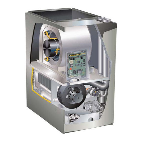
EL296DFV(X) series units are 90% efficiency gas furnaces
used for upflow or horizontal applications only, manufac
tured with Lennox Duralokt heat exchangers formed of
aluminized steel. EL296DFV(X) units are available in heat
ing capacities of 44,000 to 110,000 Btuh and cooling ap
plications up to 5 tons. Refer to Engineering Handbook for
proper sizing.
Units are factory equipped for use with natural gas. Kits are
available for conversion to LPG operation. EL296DFV(X)
model units are equipped with the icomfort
®
eLight
two-stage variable speed integrated control.
EL296DFV(X) unit meets the California Nitrogen Oxides
(NO
) Standards and California Seasonal Efficiency re
x
quirements. All units use a redundant gas valve to assure
safety shut-off as required by C.S.A.
All specifications in this manual are subject to change. Pro
cedures outlined in this manual are presented as a recom
mendation only and do not supersede or replace local or
state codes. In the absence of local or state codes, the
guidelines and procedures outlined in this manual (except
where noted) are recommendations only and do not consti
tute code.
TABLE OF CONTENTS
. . . . . . . . . . . . . . . . . . . . . . . . . . . . .
I Unit Components
. . . . . . . . . . . . . . . . . . . . . . . .
II Installation
. . . . . . . . . . . . . . . . . . . . . . . . . . . . .
III Start Up
. . . . . . . . . . . . . . . . . . . . . . . . . . . . . .
IV Heating System Service Checks
V Typical Operating Characteristics
VI Maintenance
. . . . . . . . . . . . . . . . . . . . . . . . . .
VII Wiring and Sequence of Operation
VIII Field Wiring and Jumper Settings
IX Program Unit Capacity Size Mode
X Troubleshooting
. . . . . . . . . . . . . . . . . . . . . . . .
Corp. 1126-L5
Revised 01/2018
®
- ENABLED EL296DFV(X) SERIES UNITS
®
enabled Sur
Page 2
Page 5
Page 31
Page 55
. . . . . . . . .
Page 56
. . . . . . . . .
Page 59
Page 59
. . . . . .
Page 62
. . . . . . .
Page 67
. . . . . . .
Page 71
Page 72
Page 1
EL296DFV(X)
WARNING
Improper installation, adjustment, alteration, service
or maintenance can cause property damage, person
al injury or loss of life. Installation and service must
be performed by a licensed professional HVAC in
staller (or equivalent), service agency or the gas sup
plier.
CAUTION
As with any mechanical equipment, contact with
sharp sheet metal edges can result in personal in
jury. Take care while handling this equipment and
wear gloves and protective clothing.
© 2018 Lennox Industries Inc.
Advertisement
Table of Contents
Troubleshooting

Related Manuals for Lennox EL296DF045XV36B


Summary of Contents for Lennox EL296DF045XV36B
- Page 1 EL296DFV(X) series units are 90% efficiency gas furnaces used for upflow or horizontal applications only, manufac tured with Lennox Duralokt heat exchangers formed of aluminized steel. EL296DFV(X) units are available in heat ing capacities of 44,000 to 110,000 Btuh and cooling ap...
-
Page 2: Specifications
SPECIFICATIONS Model No. EL296DF045XV36B EL296DF070XV48B EL296DF090XV60C EL296DF110XV60C Heating AFUE Performance High Input - Btuh 44,000 66,000 88,000 110,000 Fire Output - Btuh 43,000 64,000 85,000 106,000 Temperature rise range - °F 35-65 35-65 40-70 45-75 Gas Manifold Pressure (in. w.g.) 3.5 / 10.0... - Page 3 OPTIONAL ACCESSORIES - ORDER SEPARATELY NOTE - FURNACES CANNOT BE TWINNED! “B” Width Models “C” Width Models CABINET ACCESSORIES Downflow Combustible Flooring Base 11M60 11M61 CONDENSATE DRAIN KITS Condensate Drain Heat Cable 6 ft. 26K68 26K68 24 ft. 26K69 26K69 50 ft.
- Page 4 EL296DFV PARTS IDENTIFICATION CONTROL BOX (Includes integrated control, transformer and door switch) VARIABLE SPEED MOTOR (hidden) BAG ASSEMBLY (shipping location) COMBUSTION AIR INDUCER BLOWER DECK DuralokPlus HEAT EXCHANGER ASSEMBLY OUTER ACCESS PANEL COLD END HEADER BOX COMBUSTION AIR INDUCER PRESSURE SWITCH PRIMARY LIMIT BURNER BOX ASSEMBLY (includes sensor, rollout switches and ignitor)
- Page 5 I-UNIT COMPONENTS WARNING EL296DFV(X) unit components are shown in figure 1. The gas valve, combustion air inducer and burners can be ac Shock hazard. cessed by removing the access panel. Electrical compo Disconnect power before servicing. Integrated control is not field repairable. If control is inoper nents are in the control box (figure 2) found in the blower able, simply replace entire control.
- Page 6 proved during the 4-second period, the control will try four TABLE 1 more times with an inter purge and warm-up time between ® SureLight Control 5 Pin Terminal Designation trials of 35 seconds. After a total of five trials for ignition (in PIN # Function cluding the initial trial), the control goes into Watchguard-...
- Page 7 INTEGRATED CONTROL HS/ CAI LINE 1 NEUTRAL 7 SEGMENT LED FLAME SENSE INDOOR BLOWER DIAGNOSTIC CONNECTOR PUSH BUTTON DIP SWITCHES 12 PIN LOW OUTDOOR AIR VOLTAGE SENSOR CONNECTOR TERMINALS DISCHARGE AIR W915 Y1 TO Y2 SENSOR 2 STAGE COMPR TERMINALS W951 R TO O TB83 HEAT PUMP...
- Page 8 INTEGRATED CONTROL CONFIGURATION GUIDE CLG BLOWER SPEED ADJUSTMENT 2ND STAGE HEAT ON DELAY DEFAULT 7 MIN CONTINUOUS FAN MODE BLOWER SPEED UPSTAGE THERMOSTAT SELECTION DELAY + 10% MEDIUM−LOW SPEED TWO STAGE (38%) THERMOSTAT 12 MIN UPSTAGE − 10% MEDIUM−HIGH DELAY SPEED 1−STAGE (70%)
- Page 9 TABLE 4 Integrated Control Diagnostic Modes Display Action (when button released) No change (idle)* Remain in idle mode Solid “E” Enter diagnostic recall mode Solid “F” Enter flame signal mode Solid “P” (variable speed only) Program unit capacity/size (Unit Code) Soft disable Two horizontal bars __ * No change implies the display will continue to show whatever is currently being displayed for normal operation (blinking...
- Page 10 TABLE 5 Integrated Diagnostic Codes/Status of Equipment Code Diagnostic Codes/Status of Equipment Action Required to Clear and Recover Idle mode (Decimal blinks at 1 Hertz -- 0.5 second ON, 0.5 second OFF). Cubic feet per minute (cfm) setting for indoor blower (1 second ON, 0.5 second OFF) / cfm setting for current mode displayed.
- Page 11 TABLE 5 Continued Code Diagnostic Codes/Status of Equipment Action Required to Clear and Recover E 124 Active communicating thermostat signal missing for more than 3 min Equipment lost communication with the thermostat. utes. Check four wiring connections, ohm wires and cycle power at the thermostat.
- Page 12 TABLE 5 Continued Code Diagnostic Codes/Status of Equipment Action Required to Clear and Recover E 206 Gas valve second-stage relay failure Furnace will operate on 1 stage for remainder of the heating demand. Will clear after fault recovered. If unable to operate 2nd stage, replace control. E 207 Hot surface ignitor sensed open - Refer to troubleshooting.
- Page 13 TABLE 5 Continued Code Diagnostic Codes/Status of Equipment Action Required to Clear and Recover E 271 Soft lockout - Exceeded maximum number of retries. Last retry failed due Check pressure (inches w.c.) of low pressure switch to the pressure switch opening. closing on heat call.
- Page 14 TABLE 5 Continued Code Diagnostic Codes/Status of Equipment Action Required to Clear and Recover E 312 Restricted air flow in cooling or continuous fan mode is lower than cfm Warning Only. Restricted airflow - Indoor blower is setting. running at a reduced CFM (Cutback Mode - The variable speed motor has pre-set speed and torque limiters to protect the motor from damage caused by operating outside of design parameters (0 to 0.8”...
- Page 15 TABLE 5 Continued Code Diagnostic Codes/Status of Equipment Action Required to Clear and Recover E 406 LSOM - Compressor open start circuit. Required amount of current is not passing through Start current transformer. Clears the error after cur rent is sensed in START sensor, or after power re set.
- Page 16 -10% to better suit the application. Table 8 below provides Ramping Option C S Motor runs at 100% until demand is satisfied. blower speed adjustments that will result from different switch settings. Refer to tables for corresponding cfm val S Once demand is met, motor runs at 100% for 45 sec ues.
- Page 17 Continuous Fan Only speed is selectable at 28%, 38%, 70% and 100% of the selected second stage cooling speed - minimum 250 cfm. Lennox Harmony III™ Zone Control Applications - Minimum blower speed is 250 cfm. EL296DF045XV36B BLOWER MOTOR WATTS (COOLING) Motor Watts @ Various External Static Pressures - in.
- Page 18 Continuous Fan Only speed is selectable at 28%, 38%, 70% and 100% of the selected second stage cooling speed - minimum 380 cfm. Lennox Harmony III™ Zone Control Applications - Minimum blower speed is 380 cfm. EL296DF070XV48B BLOWER MOTOR WATTS (COOLING) Motor Watts @ Various External Static Pressures - in.
- Page 19 Continuous Fan Only speed is selectable at 28%, 38%, 70% and 100% of the selected second stage cooling speed - minimum 450 cfm. Lennox Harmony III™ Zone Control Applications - Minimum blower speed is 450 cfm. EL296DF090XV60C BLOWER MOTOR WATTS (COOLING) Motor Watts @ Various External Static Pressures - in.
- Page 20 Continuous Fan Only speed is selectable at 28%, 38%, 70% and 100% of the selected second stage cooling speed - minimum 450 cfm. Lennox Harmony III™ Zone Control Applications - Minimum blower speed is 450 cfm. EL296DF110XV60C BLOWER MOTOR WATTS (COOLING) Motor Watts @ Various External Static Pressures - in.
- Page 21 With Heat Pump - Cut W914 (R to DS) & W951 (R to O) on SureLight control setpoint** ® Use Dave Lennox ComfortSense 7000 thermostat Y2081 4 heat / 2 cool for this application *Dehumidification blower speed is 70% of COOL speed for all units . ®...
- Page 22 With Heat Pump - Cut W914 (R to DS) & W951 (R to O) on SureLight control ® Use Dave Lennox ComfortSense 7000 thermostat Y2081 4 heat / 2 cool for this application. *Normal operation first stage cooling blower speed is 70% COOL speed.
- Page 23 DC filter capacitors inside the controller. If the discon nect switch is bounced when the disconnect is closed, the dis Earlier ECM motors used on other Lennox furnace models are not interchangeable with motors used on connect contacts may become welded. Try not to bounce the the EL296 furnace line.
- Page 24 Motor Start‐Up Troubleshooting Motor Operation When B3 begins start‐up, the motor gently vibrates back and To verify motor operation see steps below and figures 8 forth for a moment. This is normal. During this time the elec tronic controller is determining the exact position of the rotor. and 9.
- Page 25 BLOWER B3 HARNESS CONNECTORS BLOWER B3 HARNESS CONNECTORS P48 5 Pin P49 4 Pin P48 5 Pin SHAFT SHAFT P49 4 Pin MOTOR with INTEGRATED MOTOR with INTEGRATED CONTROLLER CONTROLLER J48 5 Pin P48 5 Pin J49 4 Pin P49 4 Pin J49 4 Pin Control Connector J48 5 Pin Line Voltage Connector J48 Connector...
- Page 26 3-pin LPG change over kits are available from Lennox. Kits include motor plug. For the purpose of this test, start at either end of the connector as lead 1.
- Page 27 The switch may have a different quire no adjustment. Always operate the unit with the burner set point for each unit model number. See Lennox Repair box front panel in place. Each burner uses an orifice (see table 28 for orifice size) that is precisely matched to the burn...
- Page 28 EL296DFV Ignitor Check Test 1 Check ignitor circuit for correct resistance. Remove 4-pin plug from control. Check ohms reading across terminals 1 and 5. If value is correct, this is the only test needed. If the reading on the meter is not correct, (0 or infinity) then a second test is needed.
- Page 29 If the flue becomes obstructed during op NOTE - Each furnace model uses a unique CAI. Refer to eration, the switch senses a loss of negative pressure Lennox Repair Parts listing for correct inducer for replace ment. (pressure becomes more equal with atmospheric pres...
- Page 30 Pressure Switch Check 5 - Operate unit and observe manometer reading. Readings will change as heat exchanger warms. To check pressure switch differential, refer to figure 16 and a. Take one reading immediately after start‐up. use the provided fittings and tubing to follow the steps be b.
-
Page 31: Venting Options
II-PLACEMENT AND INSTALLATION IMPORTANT Pipe & Fittings Specifications EL296DFV exhaust and intake connections are made of PVC. Use PVC primer and solvent cement when All pipe, fittings, primer and solvent cement must conform using PVC vent pipe. When using ABS vent pipe, use with American National Standard Institute and the Ameri... - Page 32 9 - Use a utility knife to cut out the cabinet insulation for Patch Plate Top Cap the right side vent / air intake. Sheet Metal 10 -Install the two 90° street elbows (provided) through the Patch Plate side of the cabinet. The male side of each elbow should extend down through the blower deck and con...
- Page 33 Right Side Vent Configuration Side Vent Sealing Plate Side Vent Sealing Gaskets Exhaust Intake Street Elbows (2) FIGURE 19 Page 33...
- Page 34 TABLE 19 OUTDOOR TERMINATION USAGE* STANDARD CONCENTRIC Flush Wall Kit Wall Ring Kit Mount 1-1/2 inch 2 inch 3 inch Vent 2 inch 3 inch 2 inch Pipe Input Size Field Dia. in. 51W11 71M80 69M29 Fabricated 44J40 (US) 22G44 (US) (US) (US) 60L46 (US)
-
Page 35: Venting Practices
Venting Practices Joint Cementing Procedure All cementing of joints should be done according to the Piping Suspension Guidelines specifications outlined in ASTM D 2855. NOTE - A sheet metal screw may be used to secure SCHEDULE 40 the intake pipe to the connector, if desired. Use a drill PVC - 5' or self tapping screw to make a pilot hole. - Page 36 9. In areas where piping penetrates joists or interior ers and any appliances not connected to the common venting system. Turn on any exhaust fans, such as walls, hole must be large enough to allow clearance on range hoods and bathroom exhausts, so they will oper all sides of pipe through center of hole using a hanger.
- Page 37 Vent Piping Guidelines fittings. ® NOTE - Exhaust piping should be checked carefully to NOTE - Lennox has approved the use of DuraVent Centrotherm manufactured vent pipe and terminations as make sure there are no sags or low spots. ®...
- Page 38 TABLE 21 Maximum Allowable Intake or Exhaust Vent Length Size intake and exhaust pipe length separately. Values in table are for Intake OR Exhaust, not combined total. Both Intake and Exhaust must be same pipe size. NOTE - Additional vent pipe and elbows used to terminate the vent pipe outside the structure must be included in the total vent length calculation. Standard Termination at Elevation 0 - 4500 ft 2”...
- Page 39 TYPICAL EXHAUST PIPE CONNECTIONS Pipe size determined in table 21. 2” 2” 2” 2” 2” 3” TRANSITION INTAKE *2” EXHAUST DO NOT transition from smaller to larger pipe size in horizontal TOP VIEW runs of exhaust pipe. * When transitioning up in pipe size, use the shortest length of 2” PVC pipe possible. NOTE −...
- Page 40 TYPICAL EXHAUST CONNECTIONS WITH RIGHT SIDE VENT OPTION Pipe Length 4” Maximum (Not Furnished) 3” 2” 2” TRANSITION *2” 2” Plate (Furnished) Street Ell TOP VIEW (Not Furnished) * When transitioning up in pipe size, use the shortest length of 2” PVC pipe possible. NOTE Intake pipe and exhaust pipe must be the same diameter.
- Page 41 Intake Piping EQUIPMENT IN CONFINED SPACE (Inlet Air from Ventilated Crawlspace and Outlet Air to Outside) The EL296DFV furnace may be installed in either direct vent or non-direct vent applications. In non-direct vent applications, when intake air will be drawn into the furnace Roof Terminated from the surrounding space, the indoor air quality must be Exhaust Pipe...
- Page 42 doors. The EL296DFV is then classified as a direct vent, TYPICAL AIR INTAKE PIPE CONNECTIONS Category IV gas furnace. NON−DIRECT VENT APPLICATIONS In both Non‐Direct Vent and Direct Vent applications, the vent termination is limited by local building codes. In the INTAKE absence of local codes, refer to the current National Fuel SCREEN...
- Page 43 TABLE 22 Maximum Allowable Exhaust Vent Pipe Length (in ft.) Without Insulation In Unconditioned Space For Winter Design Temperatures Two - Stage High Efficiency Furnace Unit Input Size Winter Design Vent Pipe Temperatures °F (°C) Diameter 2 in. 32 to 21 (0 to -6) 2-1/2 in.
- Page 44 TABLE 23 Maximum Allowable Exhaust Vent Length Using Ventilated Attic or Crawl Space For Intake Air in Feet NOTE - Additional vent pipe and elbows used to terminate the vent pipe outside the structure must be included in the total vent length calculation. Standard Termination at Elevation 0 - 10,000 ft Number Of 2”...
-
Page 45: Vent Termination Clearances
‡ Permitted only if veranda, porch, deck or balcony is fully open on a minimum of two sides beneath the floor. Lennox recommends avoiding this location if possible. FIGURE 31... - Page 46 ‡ Permitted only if veranda, porch, deck or balcony is fully open on a minimum of two sides beneath the floor. Lennox recommends avoiding this location if possible. FIGURE 32 Page 46...
- Page 47 Details of Intake and Exhaust Piping Terminations for 6. On field supplied terminations, a minimum distance between the end of the exhaust pipe and the end of Direct Vent Installations the intake pipe without a termination elbow is 8” and a NOTE - In Direct Vent installations, combustion air is tak...
- Page 48 7. If intake and exhaust piping must be run up a side wall wall, the exhaust piping must be terminated with pipe sized per table 24.The intake piping may be equipped to position above snow accumulation or other ob with a 90° elbow turndown. Using turndown will add 5 structions, piping must be supported.
- Page 49 FIELD FABRICATED WALL TERMINATION NOTE − FIELD−PROVIDED REDUCER MAY BE 2” (51mm) 3” (76mm) REQUIRED TO ADAPT LARGER VENT PIPE SIZE Vent Pipe Vent Pipe TO TERMINATION A− Minimum clearance above grade or average 12” (305 mm) 12” (305 mm) snow accumulation B−...
- Page 50 1-1/2” (38mm) accelerator 2” EXTENSION FOR provided on 71M80 & 44W92 FURNACE 2” PVC PIPE EXHAUST kits for EL296DFV045P36B- 1” EXTENSION FOR PIPE & 070P36B 3” PVC PIPE FLASHING 12” (305mm) GLUE EXHAUST (Not Furnished) INTAKE Minimum END FLUSH INTO FURNACE Above Average TERMINATION...
- Page 51 3. If exhaust piping must be run up a side wall to position CONDENSATE TRAP AND PLUG LOCATIONS above snow accumulation or other obstructions, pip ing must be supported every 24 inches (610mm). When exhaust piping must be run up an outside wall, any reduction in exhaust pipe size must be done after the final elbow.
- Page 52 Heat cable kit is avail properly. able from Lennox in various lengths; 6 ft. (1.8m) - kit no. 26K68; 24 ft. (7.3m) - kit no. 26K69; and 50 ft. CAUTION (15.2m) - kit no.
- Page 53 TRAP / DRAIN ASSEMBLY USING 1/2” PVC OR 3/4” PVC COLD END HEADER BOX WITH 3/4” DRAIN CONNECTION Optional Condensate Drain Connection Adapter 3/4 inch slip X 3/4 inch mpt (not furnished) 90° Street Elbow 3/4 inch PVC (not furnished) Adapter 3/4 inch slip X 3/4 inch mpt (not furnished) Condensate Drain...
- Page 54 TRAP / DRAIN ASSEMBLY USING 1/2” PVC OR 3/4” PVC COLD END HEADER BOX WITH 1/2” DRAIN CONNECTION Optional Condensate Drain Connection Adapter 1/2 inch slip X 1/2 inch mpt (Not Furnished) 90° Street Elbow 1/2 inch PVC (Not Furnished) Adapter 1/2 inch slip X 1/2 inch mpt (Not Furnished) Condensate Drain...
- Page 55 III-START‐UP 4 - This furnace is equipped with an ignition device which automatically lights the burners. Do not try to light the A-Preliminary and Seasonal Checks burners by hand. 1 - Inspect electrical wiring, both field and factory installed 5 - Remove the upper access panel. for loose connections.
- Page 56 IV-HEATING SYSTEM SERVICE CHECKS through Lennox under part number 31B2001. See Corp. 8411-L10, for further details. A-CSA Certification All units are CSA design certified without modifications. Do not use matches, candles, flame or any other Refer to the EL296DFV(X) Installation Instruction.
- Page 57 NOTE- To obtain accurate reading, shut off all other gas Furnace should operate minimum 15 minutes with correct appliances connected to meter. manifold pressure and gas flow rate before checking com bustion. See sections E- and F-. Take combustion sample TABLE 25 beyond the flue outlet.
- Page 58 I- Proper Ground and Voltage 2 - In addition, measure the AC voltage from Line Hot to Line Neutral (spade terminals) on the integrated con A poorly grounded furnace can contribute to premature ig trol. See figure 53. This voltage should be in the range nitor failure.
- Page 59 V-TYPICAL OPERATING CHARACTERISTICS 3 - With only the blower motor running and the evaporator coil dry, observe the manometer reading. Adjust blow A-Blower Operation and Adjustment er motor speed to deliver the air desired according to 1 - Blower operation is dependent on thermostat control the job requirements.
- Page 60 1 - Turn off electrical and gas supplies to the furnace. against the data given in the appropriate Lennox 2 - Remove the furnace access panels. Product Specifications bulletin. Additional informa...
- Page 61 14 - Disconnect condensate line from cold end header 38 - Reinstall gas valve manifold assembly. Reconnect box. Remove cold end header box. gas supply line to gas valve. 15 - Loosen clamps on exhaust and air intake pipe seal 39 - Reinstall burner box cover if equipped.
- Page 62 VII- Wiring and Sequence of Operation Page 62...
- Page 63 the combustion air inducer will switch to high fire. After WARNING a 15 second pre-purge the high fire pressure switch will close and the unit will begin operation on high fire. Electric Shock Hazard. Can cause After 10 to 20 seconds of high fire operation the unit injury or death.
- Page 64 Applications Using A Single-Stage Thermostat 4 - After the 20-second warm-up period has ended, the gas See figure 58 for ignition control sequence valve is energized on low fire (first stage) and ignition oc curs. At the same time, the control module sends a sig B - Heating Sequence -- Integrated Control Thermostat nal to begin an indoor blower 30-second ON-delay.
- Page 65 ® icomfort Wi-Fi Thermostat with EL296DFV ® icomfort Wi-Fi Thermostat with EL296DFV and Non-Communicating Outdoor Unit and icomfortt-ENABLED Outdoor Unit ® ® icomfort Wi-Fi Thermostat icomfort Wi-Fi Thermostat icomfortt-Enabled EL296DFV Indoor Furnace icomfortt-Enabled EL296DFV Indoor Furnace Non-Communicating Outdoor Air Conditioner icomfortt-Enabled Outdoor Air Conditioner or Heat Pump icomfortt- ENABLED...
- Page 66 ® Optional Accessories for use with any icomfort Touch System ® NOTE: icomfort Wi-Fi THERMOSTAT SENSES HUMIDITY & CON TROLS HUM CONTACTS TO CYCLE HUMIDIFIER BASED ON 120V CONNECTIONS DEMAND. NO OTHER CONTROL OR HUMIDISTAT REQUIRED. “HUM” CONTACT IS OPTIONAL OUTDOOR AIR SENSOR FOR USE WITH HUMIDI CLOSED ANYTIME FIER (IF NOT ALREADY IN THE SYSTEM FOR OTHER FUNC...
- Page 67 VIII- EL296DFV Field Wiring Applications With Conventional Thermostat TABLE 29 DIP Switch Settings and On-Board Links (See figure 4) DIP Switch 1 On Board Links Must Be Cut To Select Thermostat Thermostat Wiring Connections System Options Heating Stages 1 Heat / 1 Cool FURNACE OUTDOOR T'STAT...
- Page 68 TABLE 29 EL296 Field Wiring Applications With Conventional Thermostat (Continued) DIP Switch Settings and On-Board Links (See figure 4) DIP Switch 1 On Board Links Must Be Cut To Select Thermostat Thermostat Wiring Connections System Options Heating Stages 2 Heat / 2 Cool FURNACE OUTDOOR T'STAT...
- Page 69 TABLE 29 EL296 Field Wiring Applications With Conventional Thermostat (Continued) DIP Switch Settings and On-Board Links (figure 4) DIP Switch 1 Wiring Connections Thermostat On Board Links Must Be Cut To Select Thermostat Heating System Options Stages Dual Fuel FURNACE HEAT PUMP L7724U TERM.
- Page 70 TABLE 29 EL296 Field Wiring Applications With Conventional Thermostat (Continued) DIP Switch Settings and On-Board Links (figure 4) DIP Switch 1 Wiring Connections Thermostat On Board Links Must Be Cut To Select Thermostat Heating System Options Stages Dual Fuel FURNACE HEAT PUMP L7724U TERM.
- Page 71 IX- Program Unit Capacity Size Modes − − Power-Up - Number displayed represents by integrated control unit size code (furnace model − and capacity). If three horizontal bars are displayed followed by continuous E203, furnace control does not recognize unit size code. Configure per the following: Furnace control in IDLE mode No heating, cooling or indoor fan operation)
- Page 72 X- Troubleshooting Troubleshooting: Heating Sequence of Operation CALL FOR FIRST-STAGE HEAT CALL FOR 1ST STAGE HEAT (LOW FIRE) INDOOR BLOWER OFF AFTER HEAT FAN OFF DELAY (LOW HEAT SPEED) INDOOR LIMIT BLOWER OFF HIGH ERROR WATCHGUARD − SWITCH INDOOR AFTER HEAT FAN LIMIT SWITCH CODE ERROR CODE...
- Page 73 Troubleshooting: Heating Sequence of Operation (Continued) CALL FOR SECOND-STAGE HEAT CALL FOR 2ND STAGE HEAT (HIGH FIRE) SINGLE STAGE 2 STAGE THERMOSTAT THERMOSTAT 2ND STAGE RECOGNITION DELAY ON DELAY (30 SECONDS) EXPIRED? ONLY FOR 1ST EXPIRED? REQUEST FOR 2ND STAGE HEAT INDUCER SWITCHED TO HIGH SPEED HIGH...
- Page 74 Troubleshooting: Heating Sequence of Operation (Continued) CALL FOR HEAT SATISFIED FIRST-STAGE HEAT SECOND-STAGE HEAT RUN MODE: 1ST OR 2ND STAGE CALL FOR HEAT. ALL INPUTS MONITORED (LIMIT, PRESSURE, CALL FOR HEAT/COOL, FLAME LEVEL) 2ND STAGE HEAT 2ND STAGE CALL FOR HEAT SATISFIED? DE−ENERGIZE 2ND STAGE GAS VALVE...
- Page 75 Troubleshooting: Cooling Sequence of Operation (Continued) CALL FOR COOLING 1ST STAGE COOLING REQUEST RECEIVED WAIT FOR COMPRESSOR TIMED OFF DELAY TO EXPIRE ENERGIZE 1ST STAGE COOLING CONTACTOR (COMPRESSOR & FAN) INDOOR BLOWER 2 SECOND ON DELAY ENERGIZE INDOOR BLOWER (LOW COOLING MODE) MAINTAIN INDOOR BLOWER (LOW COOLING MODE)
- Page 76 Troubleshooting: Continuous Fan Sequence of Operation CALL FOR FAN CALL FOR FAN INDOOR BLOWER ON CONTINUOUS FAN SPEED CALL FOR FAN MAINTAIN INDOOR REMOVED? BLOWER AT CONTINUOUS FAN REQUEST MAINTAIN INDOOR FOR COOLING GO TO CALL FOR COOLING BLOWER AT RECEIVED? CONTINUOUS FAN REQUEST...
Need help?
Do you have a question about the EL296DF045XV36B and is the answer not in the manual?
Questions and answers