
Related Manuals for National Flooring Equipment 3396


Summary of Contents for National Flooring Equipment 3396
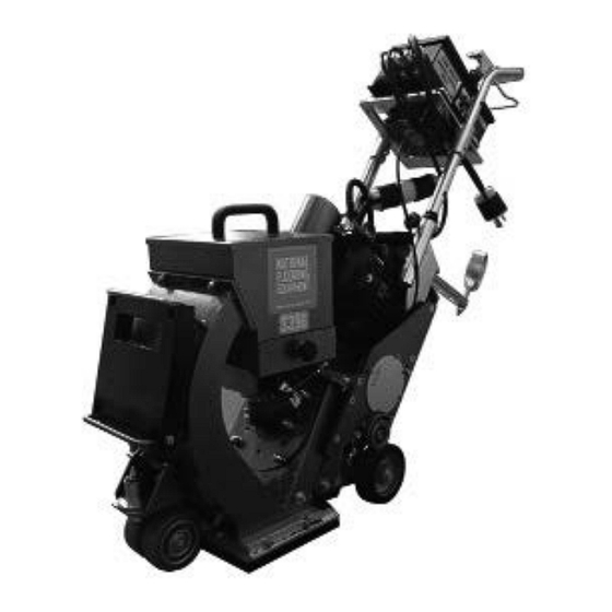
- Page 1 3396 SHOT BLASTER OPERATING MANUAL Read Manual Before Operating Machine 402561 Rev D...
-
Page 3: Table Of Contents
Table of Contents Table of Contents ................................3 Features and Specifications ............................4 Safety ....................................5 Components and Assembly ............................7 Amp Meter ................................7 Phase Reverse ..............................7 Comb Lever - Traction Drive ..........................7 Comb Lever - Abrasive Control Valve ........................7 The Wheel Kit ................................ -
Page 4: Features And Specifications
Features and Specifications Valve and Blast Wheel Control Rear-Facing Vacuum Port Adjustable Handle In-Line Air Wash Separation Systems Front Swivel Casters 8” Blast Pattern FEATURES Valve and Blast Wheel Control - Located on the machine steering Rear-Facing Vacuum Port - Incorporated into the rebound hopper to drive handle for reduced fatigue. -
Page 5: Safety
Read the manual carefully to learn equipment applications and limitations, as well as potential hazards associated with this type of equipment. Keep manual near machine at all times. If your manual is lost or damaged, contact National Flooring Equipment (NFE) for a replacement. Personal Maintenance &... - Page 6 Safety SHOT BLASTER SAFETY GUIDELINES Before use, anyone operating this equipment must read and understand these safety instructions. Dust Collection Shot Blasting Beware of hidden obtrusions. Turn off machine before working with dust collector. Watch out for hidden dangers and protrusions in flooring. Do not Do not switch off or remove the dust collector while the machine is use on largely uneven surfaces.
-
Page 7: Components And Assembly
Components and Assembly AMP METER The Amp meter (Figure 1) shows the load consumption of the blast wheel motor. When turning on the motor, the current is high (starting current peak). For no-load current and operating current, see the following values: No Load Operating <... -
Page 8: The Separator
Components and Assembly the abrasive is facing the center of the machine. Two small grooves (K) indicate the loca- tion of the control cage opening. Turning the control cage counterclockwise will move the blast pattern to the right, and turning it clockwise will move the blast pattern to the left. THE SEPARATOR (FIGURE 5) The separator (1) is mounted to the end of the rebound plenum. -
Page 9: Belt Drive
Components and Assembly BELT DRIVE The V-belt is designed for the installed drive power. Forcing the drive to grant a higher output by over tensioning the V-belt results in belt breaks, bearing damage and thus to lower efficiency. A low V-belt tension results in slippage causing an increased belt temperature and thus to premature destruction of the V-belts. -
Page 10: Preparing For Operation
Components and Assembly • Do not fix any rope or chain to the handle. Only fix ropes or chains at locations as shown (Figure 10). The handle is only fixed with two screws and cannot be used for transport or to fix ropes or hoisting equipment. •... -
Page 11: Operation
Operation START-UP PROCEDURE (FIGURE 12) Turn on dust collector (see dust collector manual). Check that the magnetic valve is closed. Push the green “Control Power” button. Set the potentiometer in a low speed setting (2-3). Push the green “Blast Wheel” button. -
Page 12: The Blast Pattern
Operation Turn the machine around by first closing the feed valve. Then turn the machine to the right and guide it in an arc to get back to the last blasted path. Repeat this in order to complete the surface. Move away from the filter towards the open surface. Move the dust collector to the surface already blasted and finished the area where the filter was located before. -
Page 13: Adjusting Magnets And Seals
Operation the steel plate. There will be a hot zone on the blasted surface where the machine has developed the highest blast intensity. The zone is nor- mally a little lighter and warmer than the rest of the blast cleaned area. Adjust the control cage until the hot zone is exactly in the middle of the blast pattern. -
Page 14: Troubleshooting Guide
Troubleshooting Guide Problem Cause Solution Reduced or no Worn blast wheel or control cage Replace worn items performance Belt tension Check and adjust belts Valve does not close properly Close valve, stop motor, re-adjust valve Too much abrasive admitted Motor must reach max. speed before opening valve Feed motion too fast Reduce speed Losing abrasive... -
Page 15: Warranty
Warranty National Flooring Equipment Inc. (referred to as “the Company”) warrants that each new unit manufactured by The Company, to be free from defects in material and workmanship in normal use and service for a period of twelve (12) months from date of shipment from the Company. For administrative ease, will honor warranty for a period of fifteen (15) months from date of shipment from the company. - Page 16 9250 Xylon Avenue N • Minneapolis, MN 55445 • U.S.A. Toll-free 800-245-0267 • Phone 763-315-5300 • Fax 800-648-7124 • Fax 763-535-8255 Web Site: www.nationalequipment.com • E-Mail: info@nationalequipment.com...
Need help?
Do you have a question about the 3396 and is the answer not in the manual?
Questions and answers