Table of Contents
Advertisement
Advertisement
Table of Contents

Related Manuals for GDS VCI

Summary of Contents for GDS VCI
- Page 1 Hardware Ver. 07. 06. 2006...
- Page 2 Qty. User’s Manual User manual with introduction and instructions for GDS System. GHDM-021400 Recovery DVD Recovery DVD for running the GDS This DVD is used to perform a full Recovery Version system recovery. (GHDM-121211) When the Information Terminal is changed, recovery DVD part number could be changed.
- Page 3 GHDM - 210000 Assy.-Trigger module The trigger module is used to manage the data during the flight record mode in the VCI module, it can also be used as a DC power supply for the VCI GHDM - 220000 module.
- Page 4 Part name Part number Description Qty. Cable-DLC [26pin -16pin] DLC main cable for communication between VCI module and (16pin) OBD-II diagnosis connector on vehicle. Length 2.0m. GHDM – 241000 Adapter [16pin-20pin(R)] DLC Adapter cable [16pin to 20pin(R)] for DLC Cable (16-26) and 20-pin diagnosis connector on vehicle.
- Page 5 Description Qty. Cable-DLC [16pin -12pin] This adapter is connected between DLC main cable [26pin to 16pin] on the VCI module and 12pin diagnosis GHDM – 245000 connecter on some specific vehicles. Length: 0.2m Adapter [16pin-6pin] This adapter is connected between...
- Page 6 For more information about self-diagnosis, see chapter A-01-006 Self-test adapter. 6p--DC jack Use this adapter when supplying power to the VCI main module without the vehicle’s battery. GHDM – 250000 AC-DC Power adapter Adapter for supplying power to the VCI main module from AC power GHDM –...
- Page 7 User’s Manual Module: A-01-001 (p.06) Part name Part number Description Qty. Cart System Cart system for protecting your GDS safely. GHDM – 5D0000 (Option Item)
- Page 8 User’s Manual Specifications and Features Hardware Module: A–01-002 (p.01) VCI Specifications General Features Item Specifications Micro Controller ARM9 (S3C2410A) @ 208MHz Memory RAM 32MByte ROM 32MByte Operating Voltage 7~35VDC Temperature Operating -10℃ ~ 70℃ (14℉ ~ 158℉): USB Mode -10℃ ~ 55℃ (14℉ ~ 131℉): Wireless LAN Mode Storage -20℃...
- Page 9 User’s Manual Module: A-01-002 (p.02) VCI (Vehicle Communication Interface) Item Specifications CAN 2.0B K-Line/L-Line ISO-9141, ISO-9141-CARB, KWP-2000 Commercial Veh. SAE-J1708, RS-232C Data/Control Line Melco Pull-Down UART Added Interface Item Specifications 1. VSS Vehicle speed simulation 2. Voltage Output 5 ~20 VDC...
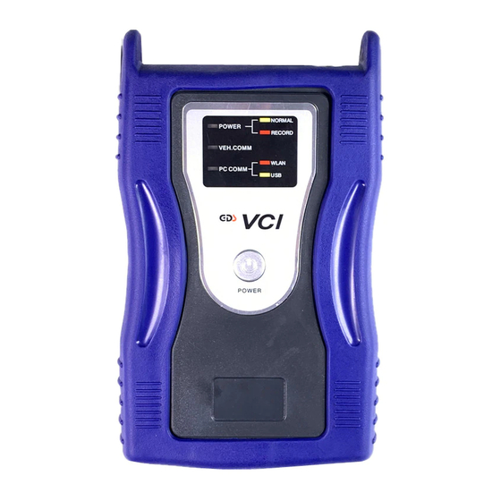
- Page 10 User’s Manual Module: A-01-002 (p.03) Main Components Power Switch VCI Status Display Mini USB Connector DLC Connector Trigger Module Connector Figure 1. Component Identification Information Terminal Specifications Refer To CF-18 Manual or your purchased lap top manual.
- Page 11 Module: A–01-003 (p.01) Turn on the VCI Module To turn on the VCI module, first connect the main DLC cable from the VCI module to the vehicle DLC connector and press the main power switch. If the vehicle DLC is not configured to provide power to the VCI, the cigar power cable must be used.
- Page 12 Green: Normal (diagnosis) mode Red: for Flight Record mode. VEH. COMM The current condition of Vehicle communication to the VCI module can be monitored using this LED. This LED is Green. Note that this LED may flicker during operation. PC COMM Communication between PC and VCI is confirmed based on LED color: Red color indicates wireless LAN connection and Green indicates USB cable connection.
- Page 13 User’s Manual Module: A-01-003 (p.03) Turn Off the VCI Module To turn off the VCI module, press the power switch for 2~3 seconds or disconnect the DLC or cigar power cable. Switch Operation of Trigger Module Trigger module switch operation (Enter / Cancel) “ENTER”...
- Page 14 User’s Manual Installation of VCI Module and DLC Main Cable Hardware Module: A–01-004 (p.01) Installation of Main DLC Cable First, confirm the position of the Data link Connector (DLC). The location of the Data Link Connector (DLC) may vary depending on the type of vehicle.
- Page 15 User’s Manual Module: A-01-004 (p.02) WARNING Do not pull on the wiring when disconnecting the DLC cable. Figure 2. Correct Method of Disconnecting Cable...
- Page 16 User’s Manual Module: A-01-004 (p.03) Installation of VCI Module The VCI should be secured in a safe location when operating the vehicle to avoid interference with other vehicle equipment. Be sure that the DLC main cable is connected securely. Figure 2. Connecting DLC main Cable to VCI module...
- Page 17 Some GDS features require using the USB cable instead of wireless LAN while communicating between the Information Terminal and the VCI module. While installing the USB cable to the VCI module, the USB cable must be tightly connected in order to avoid communication loss.
- Page 18 1. Press the lock tab 2. Remove cable Figure 4. Disconnecting the Mini USB Cable from the VCI module There are no lock tabs at the Information Terminal side connector on the USB cable, therefore use caution when checking the connecting condition between the USB cable and Information Terminal.
- Page 19 The Trigger module has two purposes. When the ignition key is turned to the IG ON position, the trigger module commands the VCI to turn ON. At that time, the VCI (if configured for flight recording) is ready to store ECU data.
- Page 20 User’s Manual Module: A-01-005 (p.02) Figure 2. Connecting cigar connector to extension cable and cigar light socket Figure 3. Connection for battery extension cable Figure 4. Installation of trigger module in a vehicle...
- Page 21 Module: A–01-006 (p.01) Purpose and Scope of Self Test (Semi-Test) The self-test functions are used to check the DLC Main Cable and specific related circuits. Not all VCI circuits are checked with the self-test functions. Basic operation of the self-test function is the loop-back theory.
- Page 22 Connecting the Self-Test Adapter Before performing the self-test function, connect the DLC Main Cable (P/N: GHDM-241000) between VCI module and Self-test adapter. Then, connect the other side of Self-test Adapter to the OBD-∥ Connector on the vehicle as shown in Figure1.
Need help?
Do you have a question about the VCI and is the answer not in the manual?
Questions and answers