Table of Contents
Advertisement
Advertisement
Table of Contents

Related Manuals for FältCom ECII Flex


Summary of Contents for FältCom ECII Flex
- Page 1 ™ FältCom ECII Flex Manual Version: 3.2.4-B Updated: 2014-08-28...
- Page 2 162187 Manual FältCom ECII™ Flex Page 2 of 40...
-
Page 3: Table Of Contents
Table of contents NOTES ..........................5 COPYRIGHT ........................5 DECLARATION OF CONFORMITY .................5 PRODUCT DESCRIPTION ....................6 Design and function....................6 Multiple ECII™ Flex connection ................7 Programming and testing ..................8 Remote programming and monitoring ...............8 4.4.1 Trygga Hissen .......................8 4.4.2 Remote Programming SW ..................8 4.4.3 Remote Programming mobile ................9 4.4.4... - Page 4 Alarm input setting ....................17 Test of alarm reception................... 19 Change of time delay for alarm button ..............20 Connections to telephone line with automatic dial/ connection......20 Automatic test alarm/routine call ................20 Incoming calls ......................22 6.12.1 Multiple units on the line ................
-
Page 5: Notes
Notes We would like to thank you for placing your confidence in Fält Communications AB (FältCom) and we are convinced that the choice of one of our security products will fulfil your expectations. In order to operate this FältCom ECII™ Flex correctly we would ask you to read this manual carefully prior to using it. -
Page 6: Product Description
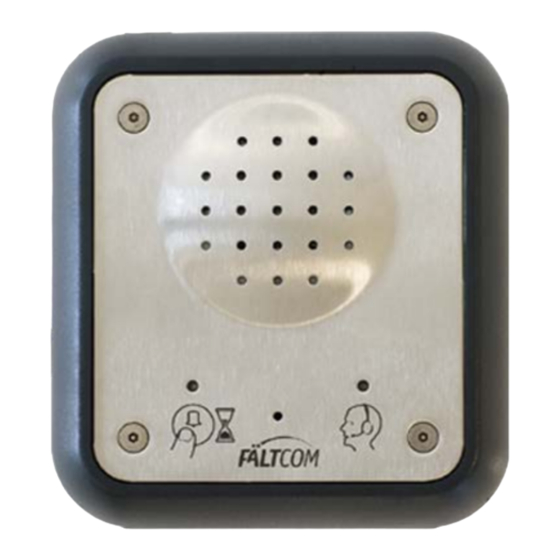
Product description The FältCom ECII™ Flex is an alarm equipment for the PSTN network with built in duplex speech communication designed for installation in lifts. When a lift passenger presses the button for alarm/emergency signal, the ECII™ Flex automat- ically calls up an alarm centre or some other predefined alarm receiver. Voice communication is established and the person in distress can talk to the staff at the alarm centre, from where help will be dispatched. -
Page 7: Multiple Ecii™ Flex Connection
ming mode. The LED’s can be programmed to display other light sequences, see section Pro- gramming for more information. The ECII™ Flex can be mounted behind the car operating panel (COP), on the panel with a small front plate and frame or with a larger front plate and frame with an integrated alarm button. The connection of the ECII™... -
Page 8: Programming And Testing
the others will listen in on the line and only pick up the line if that particular lift phone number is chosen. Connect the lift phones in parallel and place the lift phone with number 1 at the far end of the line. -
Page 9: Remote Programming Mobile
4.4.3 Remote Programming mobile The ECII™ Flex can be programmed by using an app provided by FältCom free of charge for Android or iPhone. For Android, go to Google Play shop and search for “Flex Android”, download and install. For iPhone, start the browser and enter the address: www.faltcom.se/flexconfig/index.html Follow the steps in the app and view the help section for more information. -
Page 10: Mounting Behind The Car Operating Panel
Fasten the frame first and then the lift phone with the enclosed screws. Note! Make sure the cables have been connected and the lift phone has been programmed. Mounting behind the car operating panel This alternative is only possible if there is already a prepared space for a lift phone behind the button &... -
Page 11: Connection To Telephone Line
Connection to telephone line The lift phone must be connected to a standard analogue telephone line. Normally it can also be connected to an ISDN connection via a terminal adaptor. To minimize disturbance when more than one ECII™ Flex is connected to the same telephone line it is recommended that they are connected in parallel. -
Page 12: Flat Cable Type
Check carefully that the cable will not be torn off, squeezed or chafed between the lift car and shaft wall. 5.4.3 Flat cable type Check that the cable is long enough, allow- ing a margin, to reach the telephone jack. Fasten the cable securely until it reaches the lift shaft wall. -
Page 13: Connection To Loop Amplifier
Measure to verify the correct voltage between the pins. Connect the cable to the DC converter input. Connect the DC converter to the lift phone outlet marked ”DC”. Connect the DC converter on the outside of the lift and fasten the cable with cable ties or cable clips. -
Page 14: Programming
Programming Programming of alarm numbers, alarm codes and various functions can be affected by using the keypad on the reverse of the ECII™ Flex, by calling the unit using a standard telephone or by using suitable Windows-based software. This section describes programming using the key- pad and standard telephone. -
Page 15: Activation Of Programming Mode
lapse of 30 sec. programming mode is automatically deactivated. Important! The telephone number of Alarm Receiver 1 must be programmed to make an alarm. Alarm Code 1 is default ‘1’ but must be programmed if the alarm is sent to an alarm central. Activation of programming mode 6.2.1 First time used if unit is powerless... -
Page 16: Clear All Active Alarms
Clear all active alarms This function will clear all active alarms on the ECII™ Flex. It will not remove receivers or codes, but it will make the ECII™ Flex stop calling out an alarm, without an acknowledgment of that alarm. Any new alarm input made after this will be handled normally. From keypad: ... -
Page 17: Dedicated Receiver For Input 2 And Input 3
The alarm inputs 2 and 3 can be configured to have a dedicated receiver. If the input 2 or 3 is programmed as an emergency alarm the ECII Flex will call the first attempt to INP2 or INP3 and the second attempt to the primary alarm receiver (AR1) then AR2 and so INP2 (INP3) S3 –... - Page 18 Examples of technical alarms are sum alarms from the lift controller or sensors from the lift car doors and more. Note: If the alarm input is connected to the lift controller or other external devices the connection must be separated using a relay connection. Setting of alarm input 1 By default the alarm input 1 is auto-detecting.
-
Page 19: Test Of Alarm Reception
alarm input 1 as follows: If alarm input 2 is configured as X = 0 => N/O and Y = 2 => Filtering signal it will not be possible to initiate an alarm from alarm input 1 as long as an open signal is obtained in alarm input 2. -
Page 20: Change Of Time Delay For Alarm Button
1. Alarm Receiver 1 2. Alarm Receiver 2 3. Sequence Receiver 3 4. Sequence Receiver 4 5. Sequence Receiver 5 6. Sequence Receiver 6 7. Test alarm/Routine call receiver 8. Technical alarm receiver 9. Information alarm receiver Change of time delay for alarm button The delay time on the alarm button can be set to between 1 and 30 seconds. - Page 21 It is also possible to make the ECII™ Flex call out an additional test alarm/routine call after each main alarm. To do this, use alternative 1b instead of 1a. Activation of test alarm/routine call 1 a. Select the required test interval: 1 to 30 days. (Use a number between 1 and 30.) <Days (1 –...
-
Page 22: Incoming Calls
301 < Code (max 10 digits) > # From phone: To verify the test alarm/routine call function: From keypad: 300 # From phone: Please view section 6.9 for priority order on test of receiver. To delete the test alarm/routine call receiver, test alarm/routine call interval and test alarm/routine call code: From keypad: # 300 #... -
Page 23: 6.12.2 Single Unit On The Line
From keypad: 140 < 1 – 9 > # From phone: With two or more ECII™ Flex connected on the same telephone line, one of them is pro- grammed as the master with number ‘1’. The others are coded with their individual number (2- 9) by replacing the digit with the corresponding digit. -
Page 24: Answering Time For Incoming Calls
# 141 # From phone: The active alarm mode is automatically disconnected after 6 hours, but will be extended with 6 hours if a new speech connecting alarm is made or if a call is made to the ECII™ Flex dur- ing this interval. -
Page 25: Battery Alarm From A Gsm Gateway (Art. 202236)
From keypad: # 330 # From phone: 6.14.2 Battery alarm from a GSM Gateway (art. 202236) Similar to 6.15.1 above the GSM Gateway (art. 202236) has battery back-up power in case of power failure in the building. When a battery alarm is generated in the GSM Gateway, it will signal this to the ECII™... -
Page 26: Acknowledge On End - 323
321 # From phone: Return to default acknowledgment: From keypad: # 321 # From phone: Note: If a speech message is used; press any key to stop the message. Acknowledge on end – 323 When the ECII™ Flex calls out an alarm duplex conversation is automatically connected. But if there is no answer and no tone (0-9) received the ECII™... -
Page 27: Led Flashing Sequence
The function is disconnected and return to default setting is made with: From keypad: # 710 # From phone: LED flashing sequence When the alarm button has been activated and an alarm is registered by the ECII™ Flex, the left LED on the ECII™ Flex is lit up in yellow. When the alarm is acknowledged the right LED is lit up in green and the yellow LED is turned off. -
Page 28: Info Alarm - Logging Of Alarms
To reset the alarm type to the default value, enter: From keypad: # 600 # From phone: Programmable alarm type alarm input 2 Same functionality as for alarm input 1. Changed by: <XX> From keypad: 601 <xx> # From phone: To reset the alarm type to the default value, enter: From keypad:... -
Page 29: End-Of-Alarm
For test of the alarm receiver program: From keypad: 800 # From phone: Note: If the main alarm was never acknowledged, no Info Alarm will be sent out. Also, this function will not dial out an Info Alarm following battery alarms nor test alarms/routine calls or end-of-alarm. -
Page 30: 6.22.1 End-Of-Alarm Receiver
From keypad: 610 # From phone: 6.22.1 End-of-alarm receiver End-of-alarms can be sent to a separate alarm receiver different from alarm receiver 1. If no specific alarm receiver is programmed for End-of-alarm the alarms are sent to Alarm receiver <Telephone number (max 20 digits)>... -
Page 31: Dial Tone Detection
To specify a CPC receiver: From keypad: < Receiver > 061 < Receiver > # From phone: Receiver: Alarm Receiver 1 Alarm Receiver 2 Sequence Receiver 3 Sequence Receiver 4 Sequence Receiver 5 Sequence Receiver 6 Test alarm/Routine call receiver Technical alarm receiver Information alarm receiver Dial tone detection... - Page 32 410 # From phone: Deleting message 1: From keypad: # 410 # From phone: Note: Resetting to default setting (P990P) will not clear the speech messages. Speech message 2; for the alarm receiver This message is played in the receiving telephone before the alarm call has been acknowledged by the alarm receiver.
-
Page 33: Alarm Reception
Alarm reception All tone dialling telephones (units with the keys and #) can work as simple alarm receivers. The telephone keypad is used to control alarm reception and to acknowledge the alarm un- less the need for acknowledgment has been deactivated. The most important key to learn is 4, used to acknowledge the alarm and set up the call. -
Page 34: Repeat Message 2
the alarm is disconnected by pressing , END (320, 321, 323). No more calls will be made. Repeat Message 2 If the receiver wants to hear the recorded message 2 once again press 1, REPEAT MESSAGE 2. The message can be repeated at any time during the call. Forwarding a call If you want to forward the alarm to the next alarm receiver, press 2, FORWARD. -
Page 35: Volume Control
conversation on incoming calls. End the call by hanging up or press on the receiver handset. Volume control Adjust the volume in the ECII™ Flex speaker by using a screw driver to turn the volume control. The control is located on one of the sides of the ECII™ Flex. To increase the volume;... -
Page 36: Product Label
Product label Following is a description of the ECII™ Flex product label. Liftphone Flex Unit Rev z.z Part No 202187 SW a.d.c Snr MCCCCC W yyww www.faltcom.se The product label describes: Part No 202187: Product part number (order number) Snr MCCCCC: Serial number of the product. Rev z.z: Hardware revision of the product. -
Page 37: 10 Updates
Fält Communications AB reserves the right to determine if the product will be repaired or re- placed. Warranty ceases to be valid if defects occur due to incorrect use, or other method of application, or context than specified in this manual. ECII™... -
Page 38: Service Form
Service form 162187 Manual FältCom ECII™ Flex Page 38 of 40... -
Page 39: 12 Technical Data
12 Technical data Supply voltage: Telephone line (Single mounted) If line voltage is higher than 25 VDC no external power is needed. If line voltage is between 25 VDC and 20 VDC an external power supply is required. Supply voltage: 4.5 VDC, 1500V isolation DC converter. -
Page 40: 13 Contact Information
13 Contact information Fält Communications AB Vasagatan 23 SE-903 29 UMEÅ, Sweden Support: + 46 (0)90 18 39 27 E-mail: support.liftphones@faltcom.se Phone: + 46 (0)90 18 39 00 (exchange) Fax: + 46 (0)90 18 39 29 Homepage: http://www.faltcom.se Service address: Fält Communications AB c/o BL Elektronik AB, Service Furuhedsvägen 29D...
Need help?
Do you have a question about the ECII Flex and is the answer not in the manual?
Questions and answers