Table of Contents
Advertisement
Quick Links
Advertisement
Table of Contents

Related Manuals for Ecodense RT-65 One


Summary of Contents for Ecodense RT-65 One
- Page 1 ROOF TOP SERIES CONDENSING BOILER INSTALLATION, OPERATING AND MAINTENANCE MANUAL ECODENSE RT-65 One ECODENSE RT-80 One ECODENSE RT-100 One ECODENSE RT-125 One ECODENSE RT-150 One ECODENSE RT-65 Twin ECODENSE RT-80 Twin ECODENSE RT-100 Twin ECODENSE RT-125 Twin ECODENSE RT-150 Twin...
- Page 2 DEAR USER, The Roof Top Series Condensing Boilers ECODENSE RT-65 One, ECODENSE RT-80 One, ECODENSE RT-100 One, ECODENSE RT-125 One, ECODENSE RT-150 One, ECODENSE RT-65 Twin, ECODENSE RT-80 Twin, ECODENSE RT-100 Twin, ECODENSE RT-125 Twin, ECODENSE RT-150 Twin are constructed and manufactured according to the most advance technological inventions and the safety rules.
-
Page 3: Table Of Contents
TERMS OF WARRANTY ......................... 5 Out of Warranty Conditions ........................5 GENERAL CHARACTERISTICS OF CONDENSING BOILER ............. 6 ECODENSE Roof Top Series Condensing Boilers for Outdoor Installation .......... 7 Technical Specifications ......................... 7 Boiler Safety ............................7 Standart Equipments ..........................7 ECODENSE Roof Top Series Boiler Components ................. -
Page 4: Warnings
WARNINGS Warning Symbols and Descriptions Symbols Symbol Descriptions Important information and useful hints. Warning of danger to life or property. Warning of electrical voltage. Product handling information. GAZ HATTINI TEMİZLEYİNİZ. CLEAN GAS LINE. "Clean the gas line" warning on gas line. ЧИСТАЯ... -
Page 5: General Safety Rules
General Safety Rules • All personnel engaged in installation, disassembly, commissioning, operation, control, maintenance and repair should have received the necessary training and fully read and understood this manual. • No changes that might damage the safety of the device must be made by persons and/or organizations on the device. -
Page 6: Terms Of Warranty
RT-80 One , ECODENSE RT-100 One , ECODENSE RT-125 One, ECODENSE RT-150 One, ECODENSE RT-65 Twin, ECODENSE RT-80 Twin, ECODENSE RT-100 Twin, ECODENSE RT-125 Twin, ECODENSE RT-150 Twin Roof Top Series Condensing Boilers are guaranteed for 1 year by TERMO ISI SİSTEMLERİ A.Ş. starting from the date of commissioning under the maintenance, adjustment, operating conditions and relevant mechanic, chemical and thermal effects explained herein. -
Page 7: General Characteristics Of Condensing Boiler
ECODENSE RT-65 One, ECODENSE RT-80 One , ECODENSE RT-100 One , ECODENSE RT-125 One,ECODENSE RT-150 One, ECODENSE RT-65 Twin, ECODENSE RT-80 Twin, ECODENSE RT-100 Twin, ECODENSE RT-125 Twin, ECODENSE RT-150 Twin are designed for use as standalone as well as cascade. -
Page 8: Ecodense Roof Top Series Condensing Boilers For Outdoor Installation
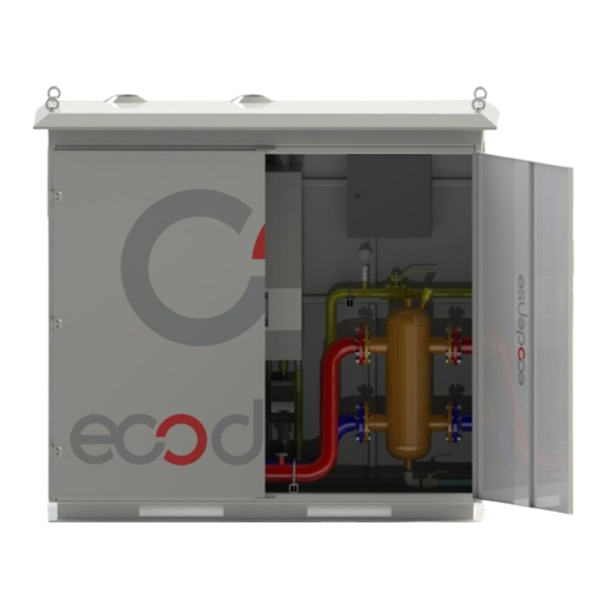
ECODENSE Roof Top Series Condensing Boilers for Outdoor Installation ECODENSE Roof Top series condensing boilers offer solution in hot water production for rooftop outdoor installation in many applications such as shopping centers, office buildings, hospitals and hotels. ECODENSE condensing boilers, when used as CASCADE, meet high-capacity energy requirements with line-up operation and also expand the life-cycle by ensuring equal aging in boilers. -
Page 9: Ecodense Roof Top Series Boiler Components
ECODENSE Roof Top Series Boiler Components ECODENSE WT 65 – ECODENSE WT 80 Material Venturi Reset Flue outlet Control card Gas valve Boiler body Ignition transformer Heater circuit return Ignition electrode Heater circuit supply Ionization electrode Automatic air relief cock... - Page 10 ECODENSE WT 100 – ECODENSE WT 125- ECODENSE WT 150 Material Venturi Reset Flue outlet Control card Gas valve Boiler body Ignition transformer Heater circuit return Ignition electrode Heater circuit supply Ionization electrode Automatic air relief cock Condensing water release outlet...
-
Page 11: Circuit Schemes
CIRCUIT SCHEMES 06.06.2017 Rev. 00... - Page 12 06.06.2017 Rev. 00...
- Page 13 06.06.2017 Rev. 00...
-
Page 14: Closed Circuit Components
CLOSED CIRCUIT COMPONENTS Balance Tank Balance Tank (Separator) must be vertical. Advantages: Ø No hydraulic response occurs between the boiler circuit and the heating circuit. Ø Boilers and heating zones operate under suitable water flow. Sizing of Balance Tank: Ø In order to ensure healthy operation of the balance tank, accurate sizing must be made. Ø... -
Page 15: Sizing Table For Expansion Tank
Sizing Table For Expansion Tank EXPANSION INLET & SYSTEM TANK OUTLET CAPACITY DIAMETER(D) DIAMETER(Ø) 1035 1150 1265 1380 1495 1610 1725 06.06.2017 Rev. 00... -
Page 16: Expansion Tank
Expansion Tank Expansion tank fore pressures must be adjusted according to system. Expansion tank should be placed parallel to circuit return line. Manometer A manometer with capacity of at least 0 to 6 bar must be connected to system. Manometer should be placed to easily visible spot from filling point, preferably same point as expansion tank. -
Page 17: Water Quality
WATER QUALITY 1. Before connection of condensing boilers any dirt and residue in circuit must be cleaned. 2. Refined water must be used while adding water to heating circuit due to any loss in closed circuit. 3. Permitted water hardness for water used in water circuit must comply with VDI 2035 standard. The lime dissolved in water, settles on hot surfaces and forms an insulation layer when water temperature rises. -
Page 18: Technical Data
BOILER TYPE CAPACITY OPERATING GAS INLET NUMBER PRESSURE PRESSURE mbar ECODENSE RT-65 One ECODENSE RT-80 One ECODENSE RT-100 One ECODENSE RT-125 One ECODENSE RT-150 One ECODENSE RT-65 Twin ECODENSE RT-80 Twin ECODENSE RT-100 Twin ECODENSE RT-125 Twin ECODENSE RT-150 Twin... - Page 19 TECHNICAL SPECIFICATIONS Unit WT 80 WT 100 WT 125 WT 150 WT 65 Capacity 80,0 100,0 125,0 150,0 Maximum Heating Capacity 20,0 25,0 25,0 25,0 Minimum Heating Capacity 63,7 78,4 98,0 122,5 147,0 Maximum Thermal Output (80°C / 60°C) Minimum Thermal Outlput (80°C / 60°C) 19,7 19,7 24,6...
-
Page 20: Condensing Boiler Dimensions
Condensing Boiler Dimensions Device must be shipped in original packaging! Clean the inside of fuel line thoroughly before installing the burner to the fuel line. Any damage that may occur due to solid objects and metal particles from the fuel line shall not be covered by our company. -
Page 21: Installation
INSTALLATION General Controls Ø The heating capacity of the device should be determined based on the heat requirement calculated. Ø All parts necessary for the system must be available. Ø Make sure that all protection and safety devices are available. Ø... -
Page 22: Stack Connections
STACK CONNECTIONS 1. Horizontal stack extensions must be connected to boiler at 1.5°-3° angle in order to drain condensing fluid. 2. Stack setup must be according to local ventilation conditions. 3. Stack connections must be leak proof. Some examples of stack setup can be seen below: 06.06.2017 Rev. -
Page 23: Assembly
ASSEMBLY ECODENSE Assembly Instructions ECODENSE condensing boilers are designed to work as CASCADE; they provide suitable space utilization for every stokehold design at required capacities. ECODENSE Single/CASCADE Assembly Instructions Ensure that required gas pressure supplied. Check the hydraulic circuit according the PID. -
Page 24: Ecodense Control Instructions Before Start-Up
Wires of boiler feed and other equipment on circuit belong to user. On first start-up if there is deficiency in the system detected by ECODENSE authorized service technicians, technicians are not allowed to activate the system. -
Page 25: Electrical Diagram
ELECTRICAL DIAGRAM 06.06.2017 Rev. 00... -
Page 26: Commissioning
COMMISSIONING Before Commissioning Ø Open all open/closed valves between the device and systems. Ø Check gas connections by using foam and water solution for determining leakages on connections carefully. Ø Check the initial pressure of expansion tank. Ø Fill the water system. Ø... -
Page 27: Adjusting Combustin Paramaters
ADJUSTING COMBUSTIN PARAMATERS Instructions below are specially prepared for ECODENSE service technicians. Before shipment parameters of all the boilers are adjusted at suitable capacity and pressure at factory’s test stand. Settings mentioned below are for combustion optimization at field conditions. Appropriate allen keys and wrenchs must be used for screws and caps. -
Page 28: Adjusting Minimum Capacity
Adjusting Minimum Capacity 1. Connect probe of flue gas analyzer to measurement point. 2. Connect a manometer to the gas feed pressure measurement point and control if the pressure is at suitable value. 3. In order to operate the boiler at minimum capacity activate cooling mode via A button. “Controller stop function on “) Press selecting heating button for 3 seconds ( will be seen on the... -
Page 29: Adjusting Maximum Capacity
Adjusting Maximum Capacity Via Adjusting of room Comfort setpoint button set boiler capacity to 100%. Later when you press OK button, boiler will start working at medium capacity According to flue gas measurement values at maximum capacity, use A and C points for gas flow rate. -
Page 30: Maintenance
MAINTENANCE Monthly Maintenance Monthly maintenance is a comprehensive process where general checks of condensing boiler and peripheral components are performed to prevent possible faults. After completion of maintenance and adjustment processes, make sure to perform an emission analysis. Ø Clean gas and water line filters. Ø... -
Page 31: List Of Error Code
LIST OF ERROR CODE Error Error Description Code Code Exterior temperature, sensor error Boiler temperature 1, sensor error Solid fuel boiler temperature, sensor error General flow water temperature, sensor error Flue gas temperature, sensor error Flow water temperature 1, sensor error Flow water temperature 1, cooling, sensor error Flow water temperature 2, sensor error Flow water temperature, main control device, sensor error... - Page 32 Error Error Description Code Code Temperature limit safety closing Water pressure is very high Water pressure is very low Water pressure switch disengaged Heating circuit 1 flow water temperature not reached Heating circuit 2 flow water temperature not reached Maximum boiler temperature exceeded DHW supply temperature not reached DHW legionella temperature not reached Flame loss in operation...
- Page 33 Error Error Description Code Code Maximum time per charging exceeded Maximum time for charging per week exceeded Heating circuit error Motor monitoring Diverter valve fan air error Boiler error Sensor error Pressure control Flow sensor error for efficiency measurement Return sensor error for efficiency measurement Pool sensor error Flow water temperature 3 sensor error...
- Page 34 Error Error Description Code Code Accumulation tank address error Main control device/system pump, address error Unpressurized cap, address error B10 sensor is lost Heating circuit 3 flow water temperature Heating circuit 3 temperature limiter Additional module 3 Sitherm Pro calculation BV step motor Drift test limit value Drift test is prevented...
-
Page 35: Solution Recommendations For Some Of The Problems
SOLUTION RECOMMENDATIONS FOR SOME OF THE PROBLEMS Problem Cause Explanation-Recommendation Gas line/Gas Control of leak proofing of connections is required. Gas smell connections Be sure that measurement points are closed. Be sure that flue connections are leak proof and Unburned gas smell Flue tightness measurement points are closed. -
Page 36: After Sales Services
Tel: +90 282 685 44 80-81 Fax: +90 282 685 42 09 You can also reach us through www.ecodense.com website and servis@ecodense.com e-mail address. Please observe the following recommendations. • Use the product in accordance with the principles of this manual. -
Page 37: Notes
NOTES Please record and forward your measurements and observations to us. www.ecodense.com 06.06.2017 Rev. 00...
Need help?
Do you have a question about the RT-65 One and is the answer not in the manual?
Questions and answers