Table of Contents
Advertisement
Advertisement
Table of Contents

Related Manuals for Godrej SEE THRU PRO


Summary of Contents for Godrej SEE THRU PRO
-
Page 1: User Manual
SEE THRU WiFi Video Door Phone USER MANUAL INDOOR UNIT Attend to your visitor anywhere, at anytime! The introductory information in this document may be changed for product improvement without prior notice. We reserve the right of final explanation and revision. -
Page 2: Table Of Contents
Table of Contents 1. Features And Functions ................2 2. Packing Contents ..................2 3. Name And Functions Of Each Part ............3 3.1 Front And Rear Part ...............3 4. Connection Diagram ................4 4.1 System Layout ................4 4.2 Wiring Diagram ................4 5. Installation .....................6 6. -
Page 3: Warning And Caution
WARNING AND CAUTION Please make sure to follow the instructions to prevent any danger or property losses. Warning: Death or serious injury is expected Do not disassemble, install, or repair this product on your own accord Do not place the product near a hot or humid place Do not forcibly bend the cord or put a heavy object on the product Do not use water, thinner or a detergent used to wash oil products to wash the exterior... -
Page 4: Features And Functions
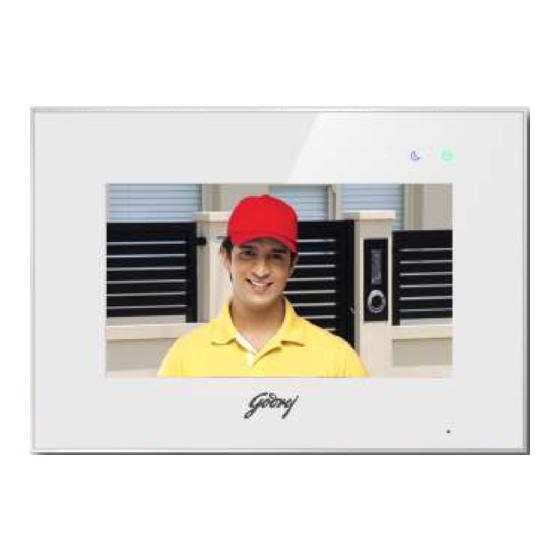
1. Features And Functions • 7” capacitive touch screen monitor,1024*600 resolution • GUI menu support sliding operation • Up to 2 door stations, 2 CCTV cameras,1 master monitor + 3 slave monitors • Built-in WiFi module can support local and remote mobile phone control (optional) •... -
Page 5: Name And Functions Of Each Part
3. Name And Functions Of Each Part 3.1 Front And Rear Part... -
Page 6: Connection Diagram
Part Name Description Micro SD Card Slot Socket for micro SD card Socket for micro USB to Rj45 (only for monitor Micro USB Slot with WiFi) Power Indicator White LED switches on when power is on Do-not-disturb/Leaving Mode Purple LED switches on when mute function is enabled / Indicator Purple LED flashes on when leaving mode is enabled Message Indicator... - Page 7 » Intercom wiring diagram with one monitor. CCTV2 VD-IN CCTV1 VD-IN VCC2 VIDEO2 VCC 2 SYV-75-5 AUDIO2 VCC1 VIDEO1 VCC 1 SYV-75-5 AUDIO1 VD I/O DATA AD I/O » Intercom wiring diagram with master monitor and extensions (please pay attention to the impedance matching switch) CCTV2 VD-IN...
-
Page 8: Installation
5. Installation » Monitor installation location Standard monitor installation height is about 1,500mm where screen center is at eye level; in this case, wall-hanging metal center is 1,450mm above ground level. » Wiring and installation of indoor monitor 1) Remove mounting bracket behind monitor and fix it on the wall with screws; 2) Pull the cable out and connect the system according to 4.2 wiring diagram;... -
Page 9: Visitor Call
6.2 Visitor Call When door station calls in, the visitor’s image will be shown on the monitor screen and you can press [Talk] icon to talk with the visitor and press it again to terminate the call. ※ Icon Definition capture a picture record a video switch between door stations... -
Page 10: Monitor Function
6.3 Monitor Function When you press the [Camera] icon on the main screen, the system will enter monitor mode, and will show image from the corresponding door station and CCTV camera. Remark: • The [Transfer] icon will be disabled in monitor mode. 6.4 Multimedia 6.4.1 Image &... -
Page 11: Voicemail Function
6.4.3 Voicemail Function Press the [Setting] icon on the main screen and enter [Voicemail] setting page, press [For visitor] icon, and then you can record and review messages. Remarks: • The monitor supports up to two voice messages for visitors. When full, the newest message will automatically overwrite the oldest message. - Page 12 ※ Add a new device When the monitor is in [WiFi] setting page, select “WiFi factory setting” item to reset WiFi; IOS system should connect with monitor UID (starts with letters “UID”), while Android system connects to home router before configuration. Open the application «MyBell», press the “+”...
- Page 13 ◆ Android system Note: If your device's WiFi is already configured before, please reset WiFi first, you can operate it on your door intercom monitor ① ② ③ ④ ⑤ ⑥ APP download address: IOS — app store; Android — Google Play; Remarks: When configuring the WiFi settings on cellphone, if you input the wrong password,you need to Ÿ...
-
Page 14: Control The Monitor By Cellphone
※ Add a connected device Step 1&2 can refer to the above operation. Open the application «MyBell», click the “+” icon and select “Device connected to network” icon; Select “Online Device” or “Manual Adding” icon (select “online device” when cellphone and device connect to the same wifi, select “manual adding”... -
Page 15: Call Forwarding Latency
switch between CAM1/CAM2 full-screen display release door lock hold to talk release the electric lock open the automatic door 6.6.3 Call Forwarding Latency 1.When the monitor is in [WiFi] setting page, select "call forwarding latency" icon to set the time for call forwarding latency; 2.Press the setting icon at the upper-right corner and turn “Ring Alerts”... - Page 16 In [Time] setting page, you can set the date & time of the monitor and select the date format. Ÿ In [Mute] setting page,you can enable/disable the mute function and set the time range of do not disturb Ÿ mode. In [General] setting page,you can set the language of the monitor and restore system to factory settings Ÿ...
-
Page 17: Specifications
7. Specifications ※ Indoor monitor Category Specification Input power DC: 14.5V TFT LCD 7 inch digital IPS LCD LCD Resolution 1024(RGB) x 600 Connection with door station Support two 4-wire door stations Connection with extension monitor Support three extension monitors Connection with CCTV Support two 2-wire CCTV input Micro SD card: 1000 images, 128 videos... - Page 18 NOTES...
- Page 19 NOTES...
- Page 20 Toll-free: 1800 209 9955 | SMS 'GSS' to 53636 | Email: secure@godrej.com | Visit: www.godrejsecure.com In view of the Godrej Policy of continuous development and improvement, the dimensions of the products as seen on the catalogue may not match with the actual product. The colour combinations of the products as seen on the catalogue may vary and not match with the actual colour of the product due to printing limitations.