Table of Contents
Advertisement
Advertisement
Table of Contents

Related Manuals for SICK RAM620-10x01


Summary of Contents for SICK RAM620-10x01
- Page 1 O P E R A T I N G I N S T R U C T I O N S Security Systems...
- Page 2 Operating instructions RFID Access Management This work is protected by copyright. Any rights derived from the copyright shall be reserved for SICK AG. Reproduction of this document or parts of this document is only permissible within the limits of the legal determination of Copyright Law.
-
Page 3: Table Of Contents
Connecting an RFID interrogator to a connection module .....35 5.3.2 Connecting the power supply/switching output in the connection module ................36 5.3.3 Inserting the cloning module ............37 5.3.4 Connecting the additional switching output of the connection module ................38 8018582/2015-11-03 Operating instructions| SICK Subject to change without notice... - Page 4 Contents Operating instructions RFID Access Management Connecting the configuration PC to the network ..........38 SICK connection accessories ................39 Commissioning RFID Access Management ............... 40 Switching on the system ..................40 Installing ECS on the configuration PC .............. 40 6.2.1...
- Page 5 RFU62x dimensional drawing ............105 10.2.3 CDB620 connection box dimensional drawing ......106 11 Annex .......................... 107 11.1 List of tables ..................... 107 11.2 List of figures ....................108 11.3 Keywords index ....................109 8018582/2015-11-03 Operating instructions| SICK Subject to change without notice...
-
Page 6: About These Operating Instructions
Qualified personnel, such as service technicians maintenance, and replacement of or industrial electricians system components Commissioning and configuration Qualified personnel, such as service technicians or engineers Tab. 1: Target group Operating instructions | SICK 8018582/2015-11-03 Subject to change without notice... -
Page 7: Information Depth
RFID waves Radio Frequency Unit = Writer and reader for RFID system RFID Access Management = System for managing access rights based on RFID SICK OPEN PORTAL for APPLICATION and SYSTEMS Engineering Tool = SICK configuration SOPAS software 8018582/2015-11-03 Operating instructions| SICK... -
Page 8: Symbols Used
Carefully read and follow the instructions for action. Instructions for taking action are indicated by an arrow. Carefully read and follow the instructions for action. Operating instructions | SICK 8018582/2015-11-03 Subject to change without notice... -
Page 9: Safety
Ethernet connections when connecting the RFID interrogators to the Ethernet • Basic knowledge of how to use an HTML browser (e.g., Internet Explorer) to access the online help Tab. 2: Qualified safety personnel 8018582/2015-11-03 Operating instructions| SICK Subject to change without notice... -
Page 10: Application Of The System
If used in any other way or if alterations are made to the system or the devices are opened – including in the context of mounting and installation – this will void any warranty claims directed to SICK AG. Operating instructions | SICK... -
Page 11: General Safety Notes And Protective Measures
(the example here shows a risk of damage to the eye by laser beams). NOTE Denotes a potential risk of damage or functional impairment to the device or the devices connected to it. This symbol includes a reference to supplementary technical documentation. 8018582/2015-11-03 Operating instructions| SICK Subject to change without notice... -
Page 12: General Safety Notes
Awareness of potential sources of danger in the system will help you to work in a safer manner and thus prevent accidents. To avoid risks, please also observe the special warnings in each of the individual chapters. Operating instructions | SICK 8018582/2015-11-03 Subject to change without notice... - Page 13 RFID interrogator can charge the metal housing to a dangerous voltage, cause malfunction and destruction of devices as well as damage to the cable shielding through heating, and thus cause cable fires. 8018582/2015-11-03 Operating instructions| SICK Subject to change without notice...
-
Page 14: Protection Of The Environment
Do not open the housing of the RFID interrogator. The device is sealed. If the device is opened, any warranty claims against SICK AG will be void. The cover on the card slot can be removed to insert the microSD card. -
Page 15: System Description
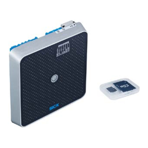
Scope of delivery RFID Access Management is available in various system configurations. RAM620-10x01 The RAM620-10x01 system variant is used to monitor one access point. Fig. 1: RAM620-10x01 scope of delivery Part no. - Page 16 • An RFU62x RFID interrogator configuration device to read the tags. • A configuration PC with Entry Exit Configuration Software to manage the access rights of persons and vehicles and to assign tags. • An Ethernet switch. Operating instructions | SICK 8018582/2015-11-03 Subject to change without notice...
-
Page 17: Specific Features
• Mounting kits for mounting the RFID interrogators (see chapter 4 Setup and mounting). • Network device for connecting the RFU62x configuration device and connecting cables (see chapter 5.5 SICK connection accessories). • CDB650 connection module for each RFID interrogator to cover extended distances between the RFID interrogator and the connections. - Page 18 The RFU62x and RFU63x RFID interrogators used in RFID Access Management process all standard passive tags in accordance with ISO-/IEC-18000-6C and EPCglobal UHF C1G2 in the regional UHF carrier frequency range. Operating instructions | SICK 8018582/2015-11-03 Subject to change without notice...
- Page 19 CMC600-101 cloning module must also be connected there. The cloning module supports the connected RFID interrogator with two additional inputs and outputs. Fig. 6: Operation with connection module and cloning module 8018582/2015-11-03 Operating instructions| SICK Subject to change without notice...
-
Page 20: Operating Principle Of The Management Software
The period during which access is permitted is stored by means of corresponding time frames. Access profiles are initially defined without reference to persons or vehicles. Operating instructions | SICK 8018582/2015-11-03 Subject to change without notice... - Page 21 Managing authorized participants and tags Updating access rights All access-related information about the participant is transferred to the corresponding RFID interrogators. The transfer takes place automatically for all RFID interrogators connected to the configuration PC. 8018582/2015-11-03 Operating instructions| SICK Subject to change without notice...
- Page 22 RFID interrogators that are not permanently connected to the configuration PC have to be updated manually by means of a direct connection between the configuration PC and RFID interrogator. Fig. 10: Updating access rights Operating instructions | SICK 8018582/2015-11-03 Subject to change without notice...
-
Page 23: Notes On The Tags
The tags are not included with delivery. Therefore, please observe the notes below when selecting tags. Recommended tags Fig. 11: Recommended tags No. Type Explanation SICK part no. No. ISO card tag For use as a personnel badge 6051820 On-metal tag For mounting on the metal surface... -
Page 24: Status Indicators
UHF field is present and tags have been detected. The LED indicators can be set via RFID Access Management (see chapter 6.9.4 Configuring the RFID interrogator indicators). Operating instructions | SICK 8018582/2015-11-03 Subject to change without notice... -
Page 25: Rfu63X Rfid Interrogator
UHF field is present and tags have been detected. The LED indicators can be set via RFID Access Management (see chapter 6.9.4 Configuring the RFID interrogator indicators). 8018582/2015-11-03 Operating instructions| SICK Subject to change without notice... -
Page 26: Cdb650 Connection Module
S4 (CMC) Integration of the CMC600 YES: CMC600 connected in cable for AUX interface of the ID sensor NO: No CMC600 inserted Tab. 7: Configuration switches in the CDB650 connection module Operating instructions | SICK 8018582/2015-11-03 Subject to change without notice... -
Page 27: Cmc600 Cloning Module
(briefly on, mainly off) cloning module. Permanently on The cloning module is operational. The RFID interrogator has successfully accessed the cloning module. Tab. 10: Green monitoring LED in the cloning module 8018582/2015-11-03 Operating instructions| SICK Subject to change without notice... -
Page 28: Setup And Mounting
No objects (including persons) must be positioned between the RFID interrogator and the tag during the read process. This would attenuate and reflect the generated UHF field and thereby reduce the scanning range and processing speed of the RFID interrogator. Operating instructions | SICK 8018582/2015-11-03 Subject to change without notice... - Page 29 5° must be observed. With a RFU62x, the recommended approach angle is 10°. Fig. 18: Selecting the approach angle of the RFID interrogators in the case of a large metal surface on the front 8018582/2015-11-03 Operating instructions| SICK Subject to change without notice...
-
Page 30: Rfu62X Rfid Interrogator
RFU62x RFID interrogator Mount the RFU62x where shocks and vibrations are minimized. For the purposes of mounting, five SICK mounting kits are available as accessories. The mounting kits can also be combined. 1. Mount the mounting kit on the RFU62x. -
Page 31: Rfu63X Rfid Interrogator
RFU63x RFID interrogator Mount the RFU63x where shocks and vibrations are minimized. For the purposes of mounting, three SICK mounting kits are available as accessories. The mounting kits can also be combined. 1. Mount the mounting kit on the RFU63x. -
Page 32: Electrical Installation
17-pin pre-assembled connecting cable with M12 female connector. This power supply unit is available as SICK accessory (see chapter 5.5 SICK connection accessories). 1. Connect the female connector of the connecting cable to the PWR, AUX, CAN I/O connection and screw together the plug connector. -
Page 33: Connecting Rfu6Xx Rfid Interrogators
Fig. 20: Connection of the RFID interrogators (overview) The switching output is configured via ECS. Note If you download the Entry Exit Configuration Software system component from the SICK Note website, you can insert the microSD card straight into the device. The microSD card must only be used when the power to the RFID interrogator has been disconnected. -
Page 34: Connecting The Power Supply/Switching Output
Switching output 2 Brown-green Switching input 2 White-yellow Yellow-brown White-gray * The color codes are valid for cables with part no. 6042772 (3 m) and part no. 6042773 (5 m). Operating instructions | SICK 8018582/2015-11-03 Subject to change without notice... -
Page 35: Connection To The Network
2. Run the cable to the connection module. 3. Connect the male connector of the connecting cable to the M12 female connector of the connection module and screw together the plug connector. 8018582/2015-11-03 Operating instructions| SICK Subject to change without notice... -
Page 36: Connecting The Power Supply/Switching Output In The Connection Module
Tab. 13: Terminals for power supply in the connection module 3. For the digital switching output connection, use terminals 20 or 21. Fig. 24: Connection of the digital switching output in the connection module Operating instructions | SICK 8018582/2015-11-03 Subject to change without notice... -
Page 37: Inserting The Cloning Module
5. Set the write protection switch of the CMC600 to the top position (OFF) if you wish to describe the CMC600 memory. Fig. 26: Write protection switch in the cloning module 6. Set the S1 (Power) switch back to ON. 8018582/2015-11-03 Operating instructions| SICK Subject to change without notice... -
Page 38: Connecting The Additional Switching Output Of The Connection Module
• Setting the transmitting power of the RFID interrogators with SOPAS (see 6.5.3 Testing RFU transmitting power). • Configuring RFID interrogators that are not permanently connected to the configuration Fig. 29: Direct connection between the configuration PC and RFID interrogator Operating instructions | SICK 8018582/2015-11-03 Subject to change without notice... -
Page 39: Sick Connection Accessories
Electrical installation Operating instructions Chapter 5 RFID Access Management SICK connection accessories Accessory Description Part number Power supply unit Power supply unit with pre-assembled M12 2062249 female connector, 17-pin for connecting the RFID interrogator to the power outlet Connecting cable for Connecting cable with M12 male connector, Power/I/O, etc. -
Page 40: Commissioning Rfid Access Management
If the setup on the microSD card cannot be started or you wish to perform the installation Note later on, copy the content of the microSD card to a temporary directory on the configuration PC. Retrieve the corresponding setups from there. Operating instructions | SICK 8018582/2015-11-03 Subject to change without notice... -
Page 41: Installing Ecs
4. The Setup Wizard reports that the installation has been completed successfully on the final screen. 5. Close the Setup Wizard. 8018582/2015-11-03 Operating instructions| SICK Subject to change without notice... -
Page 42: Installing The Sopas Configuration Software
Chapter 6 Operating instructions RFID Access Management Downloading and installing the version via the Internet Alternatively, you can download and install ECS via the SICK AG website. 1. Open the www.sick.de website in the browser. 2. Click Downloads Software to switch to the download area and narrow down the list of downloads via the Configuration software category. -
Page 43: Altering The Ip Addresses Of The Rfid Interrogators
All RFID interrogators are connected to the configuration PC either directly or via the company network. Launch SOPAS by double-clicking the program icon on the desktop. The initial screen is displayed. 8018582/2015-11-03 Operating instructions| SICK Subject to change without notice... -
Page 44: Connecting The Configuration Pc To Rfid Interrogators
2. Select the Connect to specific device option and then choose the RFU6xx device type from the list. This restricts the search for connected devices to just RFID interrogator type devices. 3. Click Next to confirm your selection. Operating instructions | SICK 8018582/2015-11-03 Subject to change without notice... - Page 45 3. Click Next to confirm your selection. All connected RFID interrogator type devices are shown with their default IP address. The red status of the connector symbol indicates a discrepancy between the IP address number ranges of the RFID interrogator and the configuration PC. 8018582/2015-11-03 Operating instructions| SICK Subject to change without notice...
-
Page 46: Altering The Default Ip Address
1. Select the RFID interrogator in the list of devices that have been found. 2. Click the Manually button and assign a free IP address in the network to the device. Operating instructions | SICK 8018582/2015-11-03 Subject to change without notice... - Page 47 RFID interrogator correctly via its IP address. 4. Proceed as follows for the other RFID interrogators. The RFID interrogator uses two ports (like all SICK devices). Ports are part of the Note network address and can be used to establish various connections between the devices.
-
Page 48: Displaying Devices In The Project Tree
RFID interrogators at the access points. 1. Go to the toolbar and click the Save Project button. 2. Select a directory and file name and then confirm your choice. Operating instructions | SICK 8018582/2015-11-03 Subject to change without notice... -
Page 49: Inserting The Microsd Card Into Access Point Rfid Interrogators
The card slot can be accessed on the RFU63x behind the aluminum cover. Fig. 30: Card slot cover (RFU63x) Take the microSD card out of its adapter if you have not already done so. Note 8018582/2015-11-03 Operating instructions| SICK Subject to change without notice... - Page 50 4. Reattach the plastic cover and tighten the two screws. 5. Switch the supply voltage on again. Operating instructions | SICK 8018582/2015-11-03 Subject to change without notice...
-
Page 51: Setting The Transmitting Power Of The Rfid Interrogators At The Access
Alternatively, you can open the device to be configured in the project tree via the Note Connection Wizard. Select the device in the list of devices that have been found and click the Connect to new device button. 8018582/2015-11-03 Operating instructions| SICK Subject to change without notice... -
Page 52: Setting The Device Parameters
Performing a test 1. Go to the SOPAS project tree and select the following entry: RFID Interrogator Quickstart 2. Bring the supplied sample tag within reading range of the RFID interrogator. Operating instructions | SICK 8018582/2015-11-03 Subject to change without notice... -
Page 53: Changing The Password To Log In To Devices
Change these default passwords accordingly. The SOPAS password will also be stored later on in the ECS system component. 1. Click the corresponding device entry on the menu bar. 2. Select the Change password command. 8018582/2015-11-03 Operating instructions| SICK Subject to change without notice... -
Page 54: Saving The Device Configuration
2. Enter the default password password123 under Integrator. 3. Click the Login button to confirm. The password can be changed later on in ECS (see chapter 7.5.2 Changing passwords for Note user roles). Operating instructions | SICK 8018582/2015-11-03 Subject to change without notice... -
Page 55: Program Overview
Logs all actions that are reported by the individual RFID interrogators. Configuration In addition to central settings, contains the management of the access points and the configuration device. Help Calls up the operating instructions in PDF format. 8018582/2015-11-03 Operating instructions| SICK Subject to change without notice... -
Page 56: Making Central Settings
Getting started Click the Configuration icon. The settings are managed via four tabs. These are located at the bottom of the work window. The window opens with the Integrator tab. Operating instructions | SICK 8018582/2015-11-03 Subject to change without notice... -
Page 57: Information About The Tag
For example, the Tag Password field is used to define the access password for the tag user memory. This protects the tag from being overwritten. If necessary, you can choose a different password here. All tags are protected by the same password. 8018582/2015-11-03 Operating instructions| SICK Subject to change without notice... -
Page 58: Information About The Time Server
2. Only the blink mode and LED color can be defined to indicate whether a device is ready to start reading. 6.9.5 Saving settings Click the Save button. All information entered on the Integrator tab is saved in RFID Access Management. Operating instructions | SICK 8018582/2015-11-03 Subject to change without notice... -
Page 59: 6.10 Recording Access Points
PC via their IP address at the time they are created. This also concerns access points that are not permanently connected to RFID Access Management. Getting started In the Configuration window, switch to the Access Point tab. 8018582/2015-11-03 Operating instructions| SICK Subject to change without notice... -
Page 60: Recording The Configuration Device
7. If the process can be completed successfully, you can finish creating the access points by clicking OK. If configuration of the access point fails, no access point will be created. Click OK to quit Note the message window. Operating instructions | SICK 8018582/2015-11-03 Subject to change without notice... -
Page 61: Recording Rfid Interrogators For The Access Control System
Time management can only be activated for RFID interrogators that are permanently Note connected to the configuration PC and to which the connection type Permanent is therefore applied. If the connection type Temporary has been selected, the Time Management checkbox is disabled. 8018582/2015-11-03 Operating instructions| SICK Subject to change without notice... - Page 62 Select Not inverted if the switching output has the status Low and switches to the status High when it is activated as the result of a successful read result. Operating instructions | SICK 8018582/2015-11-03 Subject to change without notice...
-
Page 63: The Access Points In The System Overview
The configuration device is listed at the bottom of the window. This section can also be used later on to determine how many persons and vehicles have been recorded as participants and how many tags are registered in RFID Access Management. 8018582/2015-11-03 Operating instructions| SICK Subject to change without notice... -
Page 64: Modifying An Access Point
4. Click the Modify button. The fields at the bottom are enabled so you can make the entry. 5. Adapt the settings accordingly. 6. Click Save to complete the entry. Operating instructions | SICK 8018582/2015-11-03 Subject to change without notice... -
Page 65: 6.11 Creating Access Profiles
1. Click the New button. The fields at the bottom of the window are enabled so you can make the entry. 2. Enter a name and a meaningful description for the access profile. 8018582/2015-11-03 Operating instructions| SICK Subject to change without notice... - Page 66 If no time frame is entered for a day of the week, no access is permitted at the selected access points with this access profile. Operating instructions | SICK 8018582/2015-11-03 Subject to change without notice...
- Page 67 • The second time frame is after the first for the day of the week in question, and • None of the time frames overlap. If you fail to observe any of these rules, you will receive a corresponding notification. 8018582/2015-11-03 Operating instructions| SICK Subject to change without notice...
-
Page 68: 6.12 Creating A Participant With Access Profiles
• Tag management takes place in the top right-hand section. This is where a tag that has been read by the configuration device is displayed and assigned to a participant. Operating instructions | SICK 8018582/2015-11-03 Subject to change without notice... - Page 69 5. Assign the applicable access profiles to the participant. All access profiles saved in RFID Access Management are available for selection. An access profile is assigned by ticking the corresponding checkbox. 6. Save the participant. 8018582/2015-11-03 Operating instructions| SICK Subject to change without notice...
- Page 70 The red X symbol in the column indicates that the participant has a valid access authorization but has not yet been assigned a tag it could use to grant access at the defined access points. Operating instructions | SICK 8018582/2015-11-03 Subject to change without notice...
-
Page 71: 6.13 Assigning Tags To Participants
Please note that the tag is not very responsive at close range. Note Therefore, hold the tag just above the reading range. 2. If the tag has not yet been assigned to a participant, the Tag Search section states New Tag. 8018582/2015-11-03 Operating instructions| SICK Subject to change without notice... - Page 72 Take the tag out of the reading range. The assignment is still shown. However, the gray circle on the right next to the name of the participant now indicates that the tag is not currently being read by the configuration device. Operating instructions | SICK 8018582/2015-11-03 Subject to change without notice...
-
Page 73: 6.14 Participants And Registered Tags In The System Overview
2. If the RFID interrogator has registered a positive authorization, the digital switching output activates the opening mechanism of the access point. 3. After entry, the access point must close again automatically. 8018582/2015-11-03 Operating instructions| SICK Subject to change without notice... -
Page 74: Working With Rfid Access Management
2. Enter the default password password123 under Operator. 3. Click the Login button to confirm. The password can be changed later on in ECS (see chapter 7.5.2 Changing passwords for Note user roles). Operating instructions | SICK 8018582/2015-11-03 Subject to change without notice... -
Page 75: Modifying An Access Profile
You can sort the list of participants by column by clicking one of the column headings. Clicking repeatedly on a column heading allows you to switch between ascending and descending order. 8018582/2015-11-03 Operating instructions| SICK Subject to change without notice... - Page 76 When you make an entry, the list of participants is restricted directly to the participants that contain the entered character string. Clearing the search field Click the X symbol to clear the search field. All participants will be shown again in the list. Operating instructions | SICK 8018582/2015-11-03 Subject to change without notice...
-
Page 77: Adding Participants
The assigned tag also loses its link to the participant. It will subsequently read by the RFID Result tag as a New Tag. 8018582/2015-11-03 Operating instructions| SICK Subject to change without notice... -
Page 78: Deactivating A Lost Tag
3. The participant retains its assigned access rights but now does not have a tag. This is indicated by the red X symbol. In Tag Management, the Assigned Tag section now states Without Tag. Assign a new tag to the participant. Note Operating instructions | SICK 8018582/2015-11-03 Subject to change without notice... - Page 79 4. Once you have confirmed this, the new tag is assigned to the participant. The link to the old tag is deleted. It is no longer able to grant access for any participant. 8018582/2015-11-03 Operating instructions| SICK Subject to change without notice...
-
Page 80: Displaying The Access Authorization For A Tag
If you click the Show button, the corresponding participant is selected in the list. • If the tag has not yet been assigned to a participant, the Tag Search section states New Tag. Operating instructions | SICK 8018582/2015-11-03 Subject to change without notice... -
Page 81: Modifying The Access Authorization Of A Participant
2. Click the Modify button. The fields at the bottom are enabled so you can make the entry. 3. Modify the access authorization by selecting and deselecting the access profiles. 4. Click Save. The modified access authorization is transferred to each relevant access point. 8018582/2015-11-03 Operating instructions| SICK Subject to change without notice... -
Page 82: Checking The Access Authorization Validity
• The participant no longer has access. Not Yet Valid • Based on the current date, the From date for the access authorization is in the future. Tab. 15: Validity criteria for access authorizations in ECS Operating instructions | SICK 8018582/2015-11-03 Subject to change without notice... -
Page 83: Reading The Update Status Of The Access Points
The device status is indicated via three status LEDs, an explanatory note, and a pop-up window that opens when you move over it with the mouse. 8018582/2015-11-03 Operating instructions| SICK Subject to change without notice... - Page 84 Make sure that the current firmware has been installed on the RFID interrogators. Make sure that the microSD card has been inserted in the corresponding RFID interrogator. Tab. 16: Indication of update status in ECS Operating instructions | SICK 8018582/2015-11-03 Subject to change without notice...
-
Page 85: Viewing Access Logs
1. Launch RFID Access Management. 2. Log in with the Information Security Officer user role. 3. Use the default password password123. RFID Access Management opens directly in the Access Log view (see below). 8018582/2015-11-03 Operating instructions| SICK Subject to change without notice... -
Page 86: Filtering The List Of Access Logs
RFID interrogator. The view that is only authorized for the Information Security Officer has a red border to differentiate it from the other views. Operating instructions | SICK 8018582/2015-11-03 Subject to change without notice... -
Page 87: Closing The Access Control Display
Logout icon. Logging out as Information Security Officer You have logged in to RFID Access Management with the Information Security Officer user role. Click the Logout icon. The System Overview opens. 8018582/2015-11-03 Operating instructions| SICK Subject to change without notice... -
Page 88: Managing Rfid Access Management
Click the Configuration icon and switch to the Settings tab. Backing up data 1. Next to Save data, click the Select file button. This will open the Windows dialog box for saving files. Operating instructions | SICK 8018582/2015-11-03 Subject to change without notice... -
Page 89: Changing Passwords For User Roles
RFID Access Management against unauthorized access. 1. Click the Configuration icon and switch to the Passwords tab. 2. Enter the old password for the user role. 8018582/2015-11-03 Operating instructions| SICK Subject to change without notice... -
Page 90: Changing The User Language
3. Click OK to confirm. RFID Access Management closes. The Login window will then open so you can log back into the program. The language of the program interface has now been changed. Operating instructions | SICK 8018582/2015-11-03 Subject to change without notice... -
Page 91: Defining The Access Of The Information Security Officer To Access Logs Using The Four Eyes Principle
2. If you untick the checkbox, it is no longer possible for the Information Security Officer to log in separately. Access to the access logs then requires a second user to have logged in beforehand. 8018582/2015-11-03 Operating instructions| SICK Subject to change without notice... -
Page 92: Maintenance And Repairs
6.3 Altering the IP addresses of the RFID interrogators). No further adjustments are required in ECS. The replacement device is addressed via the Note IP address stored in the access point. Operating instructions | SICK 8018582/2015-11-03 Subject to change without notice... -
Page 93: Replacing The Rfid Interrogator At The Access Point
2. Check the status of the synchronization in the System Overview. If the access rights were able to be transferred successfully to the replacement device, the status LED of the device will be green. 8018582/2015-11-03 Operating instructions| SICK Subject to change without notice... - Page 94 Replacement devices with the connection type Temporary are also updated as soon as Device with Temporary a connection has been established with RFID Access Management. connection type The update may also have to be confirmed here by clicking Modify and Save. Operating instructions | SICK 8018582/2015-11-03 Subject to change without notice...
-
Page 95: Fault Diagnosis
As the access authorizations are saved in the RFID interrogators, all tags can be correctly read and evaluated. The connection of the connected RFID interrogators to the time server also remains intact. 8018582/2015-11-03 Operating instructions| SICK Subject to change without notice... -
Page 96: Sick Support
Hold the tag at an appropriate distance within the reading range. SICK support If you cannot remedy the fault with the help of the information provided in this chapter, please contact your respective SICK subsidiary. Fault indication on the RFID interrogator The following LEDs indicate a fault:... -
Page 97: System Logs In Rfid Access Management
Use the drop-down menu on the left if you wish to restrict the list to messages from selected access points. Use the drop-down menu on the right if you wish to restrict the list to specific message types. 8018582/2015-11-03 Operating instructions| SICK Subject to change without notice... -
Page 98: Fault Diagnosis In Sopas
Fault diagnosis in SOPAS In the event of a fault, detailed diagnostics can also be carried out in the SOPAS configuration software. In such cases, contact SICK support. Operating instructions | SICK 8018582/2015-11-03 Subject to change without notice... -
Page 99: Technical Data
** From the point of view of the system, users are all persons who log in to RFID Access Management with one of the three user roles. Tab. 19: RFID Access Management data sheet 8018582/2015-11-03 Operating instructions| SICK Subject to change without notice... -
Page 100: Rfu63X Rfid Interrogator Data Sheet
-25 °C to +50 °C Weight 3,500 g Dimensions 239 mm x 239 mm x 64 mm * Depending on tag used and ambient conditions. Tab. 20: RFU63x RFID interrogator data sheet 100 Operating instructions | SICK 8018582/2015-11-03 Subject to change without notice... -
Page 101: Rfu62X Rfid Interrogator Data Sheet
-40 °C to +50 °C Weight 780 g Dimensions 137 mm x 131 mm x 56 mm * Depending on tag used and ambient conditions. Tab. 21: RFU62x RFID interrogator data sheet 8018582/2015-11-03 Operating instructions| SICK 101 Subject to change without notice... -
Page 102: Cdb650 Connection Module Data Sheet
Supply voltage Power consumption 500 mW Electrical safety Acc. to EN 60950-1 (2006) Weight 30 g Operating temperature -35 °C to +40 °C Tab. 23: CMC600-101 cloning module data sheet 102 Operating instructions | SICK 8018582/2015-11-03 Subject to change without notice... -
Page 103: Configuration Pc System Requirements
Windows 7 x86 Service Pack 1 Windows 7 x64 Service Pack 1 Windows 8 x86 Windows 8.1 x86 Windows 8 x64, Windows Server 2012 x64 Windows 8.1 x64 Tab. 25: Supported operating systems 8018582/2015-11-03 Operating instructions| SICK 103 Subject to change without notice... -
Page 104: 10.2 Dimensional Drawings
4 x M6 threaded mounting hole, 11 mm deep ⑧ 1 x LED, multi-colored (process feedback) ⑨ Function buttons Micro USB female connector and slot for microSD memory card, behind threaded cover 104 Operating instructions | SICK 8018582/2015-11-03 Subject to change without notice... -
Page 105: Rfu62X Dimensional Drawing
4 x LED, multi-colored (process feedback) ⑦ 7 x LED for status indicators ⑧ Cover with integrated antenna ⑨ Screw (Torx T8), captive (2x), for side cover Side cover open 8018582/2015-11-03 Operating instructions| SICK 105 Subject to change without notice... -
Page 106: Cdb620 Connection Box Dimensional Drawing
CDB620 connection box dimensional drawing Fig. 36: CDB620 connection box dimensional drawing ① ② 5 x cable gland ③ 17-pin M12 female connector, A-coded Max. screw diameter 4 mm 106 Operating instructions | SICK 8018582/2015-11-03 Subject to change without notice... -
Page 107: Annex
CDB650 connection module data sheet ............102 Tab. 23: CMC600-101 cloning module data sheet ............102 Tab. 24: Configuration PC system requirements ............103 Tab. 25: Supported operating systems ................103 8018582/2015-11-03 Operating instructions| SICK 107 Subject to change without notice... -
Page 108: 11.2 List Of Figures
Annex Chapter 11 Operating instructions RFID Access Management 11.2 List of figures Fig. 1: RAM620-10x01 scope of delivery ............... 15 Fig. 2: RAM630-10x01 scope of delivery ............... 16 Fig. 3: System components ..................... 17 Fig. 4: Operation without connection module ..............18 Fig. -
Page 109: 11.3 Keywords Index
Operation ..........74 Connection module ......19 RFID interrogator (access point) ..18 RFID interrogator (configuration) ..18 Participant Configuration PC ........18 Recording .......... 68 Connecting ........38 Participants ........... 21 8018582/2015-11-03 Operating instructions| SICK 109 Subject to change without notice... - Page 110 Safety notes ........... 11 Changing the password ....89 Scope of delivery ........15 Information Security Officer ..... 85 Settings ..........56 Integrator ........... 54 SICK support ......... 96 Operator..........74 SOPAS 110 Operating instructions | SICK 8018582/2015-11-03 Subject to change without notice...
- Page 111 Annex Operating instructions Chapter 11 RFID Access Management 8018582/2015-11-03 Operating instructions| SICK 111 Subject to change without notice...
- Page 112 E-Mail support@sick.jp 1 (800) 325-7425 – tollfree Magyarország E-Mail info@sickusa.com Phone +36 1 371 2680 E-Mail office@sick.hu Nederlands Phone +31 (0)30 229 25 44 More representatives and agencies E-Mail info@sick.nl at www.sick.com SICK AG | Waldkirch | Germany | www.sick.com...
Need help?
Do you have a question about the RAM620-10x01 and is the answer not in the manual?
Questions and answers