Table of Contents

Related Manuals for Minco CT124


Summary of Contents for Minco CT124
- Page 1 MINCO CT124 8-Channel Temperature Monitor INSTRUCTION MANUAL When quality and performance are as important as price, call... PRODUCTS, INC. 7300 Commerce Lane/Minneapolis, Minnesota 55432-3177 U.S.A. Telephone:(763)571-3121 FAX:(763)571-0927 FORM #930616-1...
- Page 2 This page left blank...
- Page 3 SPECIFICATIONS ....... . . 22 MODEL NUMBER CODING ......23 Minco Products, Inc. CT124 Instruction Manual...
- Page 4 Installation of a nearby power cutoff switch is recommended. Contact Minco before attempting any repairs. Do not remove the CT124’s rear cover. Access the inside by removing the front cover only. Many components may be damaged by static discharge. Do not touch electrical connections inside the case.
-
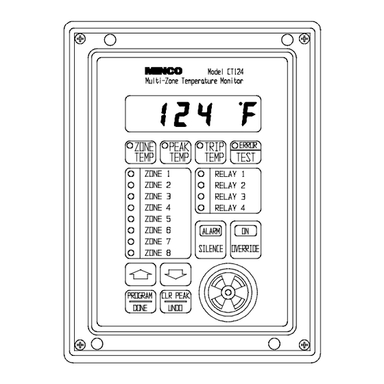
Page 5: General Description
It scans up to eight RTD’s and activates four relays plus a built-in audible alarm. In a typical application, the CT124 provides early warning of possible large machine failure by monitoring the temperature of bearings, stators, transformer coils, and oil outlets. You can configure the CT124 to many other situations such as on/off control or under-temperature alarms. -
Page 6: Installation Instructions
• from water and excessive dust inside a suitable enclosure. Do not use the CT124 in hazardous (explosive) atmospheres. • Do not expose the CT124 to continuous or excessive shock and vibration. • Mount the CT124 at any angle. •... - Page 7 You may find it more convenient to unscrew the two connector boards from the rear of the case and remove them while you are connecting the wires. In the event that the CT124 must be returned to Minco for repair, simply disconnect the connector boards and leave the wires attached to the terminal blocks.
- Page 8 "normal" acting operating state of the relays. In certain applications you may want the relays to be "reverse" acting. This means that if the CT124 loses power, the relay(s) will de-energize into the tripped or alarm state. See Figure 6 for a summary of relay states.
- Page 9 Avoid routing RTD wires along with or near electrically noisy wires such as wiring to contactors, motors, computers, etc. Electrical interference from these wires may cause instability or shifts in the CT124’s readings. For best noise immunity, use twisted and shielded extension leadwire to the RTD’s.
- Page 10 Alternative RTD Wiring Options For the best accuracy, all 3 leads of each RTD should be brought to the CT124 as shown in Figure 8. However, with some high voltage electric motors, the RTD’s have been prewired to a terminal block with one of the common leads for each RTD grounded.
- Page 11 INSTALLATION CHANGING FRONT PANEL LABELS If you wish, you can replace the zone and relay labels on the front panel of the CT124. Follow these instructions: Follow the safety precautions on page 2. Be sure power is off, then remove the CT124’s front panel and disconnect the ribbon cable.
-
Page 12: Operating Instructions
OPERATING INSTRUCTIONS GENERAL OPERATION The CT124 Multi-Zone Temperature Monitor continuously scans temperature input from 1 to 8 RTD’s (Resistance Temperature Detectors). It compares each reading to 5 separate trip points and activates relays and a built-in alarm when any RTD senses an over- or undertemperature condition. The audible alarm may be set to go off when any of the four relays are tripped, and/or independently at its own trip point. - Page 13 If the alarm is sounding, push the SILENCE button to quiet the alarm. The alarm may sound again later if the alarm condition still exists after Time of Silence has expired (see the CT124 Setup Worksheet). Any new alarm conditions will override the silence function.
-
Page 14: Programming Instructions
. The display will return to zone temperature. GENERAL PROGRAMMING INSTRUCTIONS Program Display: The CT124 display will show an operation code at the left and the selected parameter at the right. Zone, relay, and alarm lights indicate which input or output you are currently programming. examples: with the alarm light on, this programs the alarm to trip at 110°C. - Page 15 Fahrenheit. Trip points automatically convert to the new scale. Display Channel: If the keyboard has been untouched for 15 seconds, the CT124 will switch to display the highest or lowest temperature being sensed, or any (last) selected zone. Relays and Alarms: Each step is repeated for each relay and the alarm.
- Page 16 , unless you want to recalibrate. Calibration instructions are on page 20. SAMPLE WORKSHEET DESCRIPTIONS On the following pages are three sample CT124 Setup Worksheets. These will demonstrate the types of functions the CT124 can perform and how to code them into the worksheet. Worksheet 1: Monitor a transformer with three RTD’s in the phase windings.
- Page 17 SAMPLE WORKSHEET 1 (see page 14) CT124 SETUP WORKSHEET Use this worksheet to describe the setup parameters for the desired operation of the CT124. Fill in a short description of the location and purpose of each temperature sensor, and save the worksheet for future reference.
- Page 18 SAMPLE WORKSHEET 2 (see page 14) CT124 SETUP WORKSHEET Use this worksheet to describe the setup parameters for the desired operation of the CT124. Fill in a short description of the location and purpose of each temperature sensor, and save the worksheet for future reference.
- Page 19 SAMPLE WORKSHEET 3 (see page 14) CT124 SETUP WORKSHEET Use this worksheet to describe the setup parameters for the desired operation of the CT124. Fill in a short description of the location and purpose of each temperature sensor, and save the worksheet for future reference.
-
Page 20: Troubleshooting
(see below). Recovering From Error 1 If the memory test fails when the CT124 is powered up, Error1 is displayed. This is designed to occur when the useful life of the non-volatile memory has expired (typically greater than 10 years). Extreme power line transients may also corrupt the memory. - Page 21 If your display changes by more than one digit, excessive electrical noise is being introduced to the CT124, and fouling the measurements. There are a number of actions that may improve noise immunity. A few things to try are: Use twisted and/or shielded leads for the RTD’s.
-
Page 22: Calibration
. The display should now read Unplug the RTD connector board from the rear of the CT124 and replace it with the AC758. Be sure the 2-letter code of the RTD type is correct; e.g. use an AC758PD RTD Simulator with a CT124PD Controller (see model number coding on page 23). -
Page 23: Return For Repair
It is our policy to handle returns in a timely manner, but some applications may require immediate action. If your CT124 should fail and it must be replaced within hours rather than a few days or weeks, we have developed a convenient loaner/exchange program. Call Minco for details. -
Page 24: Specifications
Mounting: 3/4 DIN (DIN43700). Panel-mounted in 5.51" x 7.32" (140mm x 186mm). Extends behind panel 5.1" (130mm) maximum. Weight: 4 lbs. (1.8 kg.). Minco Products, Inc. CT124 Instruction Manual... -
Page 25: Model Number Coding
PF = 1000 Ω Platinum, TCR = 0.00385, -40 to 530°C (986°F) NA = 120 Ω Nickel, TCR = 0.00672, -40 to 250°C (482°F) CA = 10 Ω Copper, TCR = 0.00427, -40 to 250°C (482°F) Base model number: CT124 Minco Products, Inc. CT124 Instruction Manual... - Page 26 WARRANTY Items returned within one year from the date of sale, transportation prepaid, which Minco Products, Inc. (The "Seller") reasonably determines to be faulty by reason of defective materials or faulty workmanship will be replaced or repaired at the Seller’s discretion, free of charge.
Need help?
Do you have a question about the CT124 and is the answer not in the manual?
Questions and answers