Table of Contents
Advertisement
Quick Links
iVA A-SERIES OPERATING MANUAL
Cable And Network Analyzer System (iOS Version)
This document contains information which is confidential and the property of Kaelus, and which is not to be communicated to any person or
company, or used in any way without the previous authorization of Kaelus.
2017 | R99-0124RevC
Advertisement
Table of Contents

Related Manuals for Kaelus iVA0727A


Summary of Contents for Kaelus iVA0727A
- Page 1 Cable And Network Analyzer System (iOS Version) This document contains information which is confidential and the property of Kaelus, and which is not to be communicated to any person or company, or used in any way without the previous authorization of Kaelus.
- Page 2 | Cable And Network Analyzer System (iOS Version) Description of Document Document Issue Date Authorization Change Creation of document by Rev A 29/04/16 Eng (iOS) IR11200, IR11141 Section Rev B remove and in case 30/04/17 charging warning.sdsds Implementation of new Rev C 1/12/2017 Kaelus format.
- Page 3 Do not discard any packing material until notified by the carrier or Kaelus. Carefully unpack all containers and check that all items listed on the delivery documentation. Please notify Kaelus of any damaged or missing items from the shipment.
- Page 4 Operating Manual | Cable And Network Analyzer System (iOS Version) Table of Contents Operating Instructions Introduction Functional Description Features Specifications Construction and Features Installing Software 1.6.1 Installing software on your iPad Charging 1.7.1 Charging Constraints 1.7.2 Charging After the Battery has Been Run Flat 1.7.3 Charging Time 1.7.4...
- Page 5 1.16 Cable Loss Measurement 1.17 Transmission Measurement 1.18 Distance to Fault 1.19 Spectrum Monitor Measurement 1.19.1 Setting Sweep Start and Stop Frequency 1.19.2 Setting Markers 1.20 Stimulus Mode 1.20.1 Stimulus Mode Options 1.21 Setting Test Limits 1.21.1 Test Limit Options 1.21.2 Minimum Limit 1.21.3...
- Page 6 Operating Manual | Cable And Network Analyzer System (iOS Version) List of Figures Figure 1 iVA Equipment View Figure 2 Install Screen from the App Store. Figure 3 Switching on the iVA Figure 4 Select the iVA’s to connect to by Serial number Figure 6 iOS iVA Application icon Figure 5 Allowing the iVA app via Bluetooth Figure 7 iOS Application, Devices Menu...
- Page 7 Figure 31 Re-ordering Reports Figure 32 Contractor Details Menu Figure 33 Record and Photo Menu Figure 34 Tag menu Figure 35 Plot expanded view (Reports) Figure 36 Edit Plot View Figure 37 Remove a Plot Figure 38 Settings General Menu Figure 39 Settings Units ©...
-
Page 8: Operating Instructions
1. Operating Instructions Introduction This manual describes the operation of the iVA (Cable and Network Analyzer) developed by Kaelus. The iVA Cable and Network Analyzer enables users to measure Through Loss/VSWR/Return Loss and the location of the VSWR/Return Loss faults in their RF infrastructure. The Bluetooth interface allows unprecedented measurement flexibility and opens up new &... -
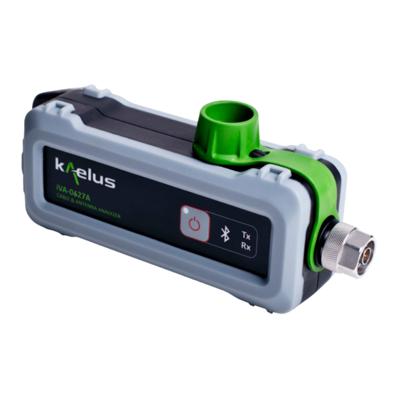
Page 9: Figure 1 Iva Equipment View
Figure 1 iVA Equipment View Power On/Off Button Power on turns on the iVA unit. A short touch will turn on the iVA, indicated by a Green LED (See item 3). A long touch until the Tx Rx activity LEDS flash then release will turn the iVA off. Bluetooth Activity LED Indicates when Bluetooth signaling is active •... -
Page 10: Installing Software
Typically the stand alone iOS installable file will be released via the App Store Figure 2 Install Screen from the App Store. 1.6.1.2 App Store releases Go to the App store and search for Kaelus iVA and press install. 1.6.1.3 Minimum System Requirements iOS 8.0 and iPhone 4... -
Page 11: Charging
Charging The iVA has a non user replaceable 3.6V Li-ion battery, that is charged via the USB port. 1.7.1 Charging Constraints There is a variety of charging currents delivered from USB Ports. Ideally your USB Port should be able to deliver 500mA of current or more. -
Page 12: Switching On Your Iva
Operating Manual | Cable And Network Analyzer System (iOS Version) Switching on Your iVA Figure 3 Switching on the iVA A momentary touch on the Power switch on the iVA. Note: the pre–use charging instructions in Section 1.7. Turn on the iVA prior to starting the iVA application. -
Page 13: Connecting To Your Ios Ipad (Application Information)
Figure 6 iOS iVA Application icon If the Kaelus iVA application icon is not visible on your iPad screen, check in the Apps menu. Typically the Program will start on the devices menu screen to allow you to first connect to the iVA, when the iVA is first switched on the Blue LED will be flashing, indicating that the iVA is not yet paired to a iPad. -
Page 14: Selecting Your Iva In The Ios Application Device Menu
Operating Manual | Cable And Network Analyzer System (iOS Version) 1.10.1 Selecting Your iVA in the iOS Application Device Menu Ensure the Bluetooth is enabled on your iOS device, the Bluetooth switch can be found in the iOS/Apple Settings menu. 1.10.1.1 Devices Menu 1.10.1.1.1... - Page 15 1.10.1.1.4 Battery Charge Indicator The Battery charge indicator, indicates the battery charge level and whether the iVA is charging via the USB port. Charging 50% Charge remaining Battery Low Battery Very Low 1.10.1.1.5 Progress Bar Shows the progress of the transfers to and from the iVA. This could be factory calibration data or firmware (ensures your iVA firmware is compatible with the application version you are using), and will occur on the first use of the iVA or after an update.
-
Page 16: Navigation Menu
Operating Manual | Cable And Network Analyzer System (iOS Version) 1.11 Navigation Menu 1.11.1.1.1 1.11.1.1.2 1.11.1.1.3 1.11.1.1.4 1.11.1.1.5 1.11.1.1.6 1.11.1.1.7 1.11.1.1.8 1.11.1.1.9 1.11.1.1.10 1.11.1.1.11 1.11.1.1.12 1.11.1.1.14 1.11.1.1.13 Figure 8 Application, Navigation Menu 1.11.1.1.1 Navigation Side Panel Menu Touch to open and touch outside the panel to close. 1.11.1.1.2 Return Loss. -
Page 17: Traces Menu
1.11.1.1.9 Devices. See Section 1.10.1 The devices menu allows you to scan and select the iVA device you want to use for your measurements. Note: Your device/s must be connected first, in the Bluetooth settings before items 1.11.1.1.2 to 1.11.1.1.4 above and item 1.11.1.1.6 are able to operate. -
Page 18: Traces Menu Options
Operating Manual | Cable And Network Analyzer System (iOS Version) 1.12.1 Traces Menu Options 1.12.1.1 Remove Trace The highlighted trace will be removed. 1.12.1.2 Shows the Trace Number. This shows the trace number for the current parameter menu, other traces could be Tr2, Tr1 and so on. 1.12.1.3 Add an Additional Trace Adds a trace to the current display channel. -
Page 19: Trace Types
1.12.1.14 Trace Math (Optional Feature) The Trace math menu can from the currently highlighted trace. Add or subtract another displayed trace, or add or subtract a previous memory trace of the highlighted trace See Section 1.12.1.12. Note : The traces will need to be the same type 1.12.2 Trace Types Different trace types can be included on the same measurement channel allowing for quick comparisons on the same... -
Page 20: Channel Menu
Operating Manual | Cable And Network Analyzer System (iOS Version) 1.13 Channel Menu Channel frequency stimulus is used by default on traces, See Figure 9 to Override Figure 10 Application, Channel Menu 1.13.1 Channel Menu Options 1. Channel menu 2. Run Selects between trace running and stopped 3. -
Page 21: Subplots
8. Record menu, take photo, choose photo, record selected trace. 9. Record Icon 10. State Menu. See Section 1.23 11. Subplots. See Section 1.13.2 1.13.2 Subplots Subplots determine how traces are displayed in a given channel. Having 1 subplot will cause the whole trace screen to be used and all traces in that channel to be displayed on top of each other. -
Page 22: Trace Zoom Functions
Operating Manual | Cable And Network Analyzer System (iOS Version) 1.14 Trace Zoom Functions. Figure 12 Application X axis Zoom Figure 13 Application Y Axis Zoom... -
Page 23: Figure 14 Application X And Y Zoom Together
Figure 14 Application X and Y Zoom Together 1.14.1 1.14.2 Figure 15 Double tap and Slide Zoom © 2017 Infinite Electronics, Inc., All Rights Reserved. -
Page 24: Trace Autoscale
Operating Manual | Cable And Network Analyzer System (iOS Version) 1.14.1 Trace Autoscale 1.14.1.1 Autoscale (Short Press) The currently selected trace will autoscale to fit the current screen or subplot area. 1.14.1.2 Autoscale (Long Press) All traces on the display will autoscale to fit in their respective screen or subplot areas. 1.14.2 Trace Rest Scale 1.14.2.1... -
Page 25: Cable Loss Measurement
Transmission mode allows you to characterize insertion loss between two or more points. For transmission mode between 2 and 4 iVA’s need to be connected. See Section 1.9, allow each Bluetooth device to communicate with the Kaelus iVA Application. Make note of the ports each iVA is connected to. Setup the transmission traces required between the ports in the traces menu. -
Page 26: Distance To Fault
Operating Manual | Cable And Network Analyzer System (iOS Version) Figure 17 Transmission Calibration Menu 1.18 Distance to Fault Figure 18 Distance to Fault Display, iOS Application... -
Page 27: Spectrum Monitor Measurement
1.19 Spectrum Monitor Measurement 1.19.1 Setting Sweep Start and Stop Frequency 1.19.1.1 1.19.1.2 1.19.1.3 1.19.1.4 1.19.1.5 Figure 19 Spectrum Monitor, Override Stimulus 1.19.1.1 Spectrum Monitor Sensitivity Range A Pull down menu has 2 sensitivity ranges, -50dBm to +20dBm and -115dBm to -35dBm 1.19.1.2 Override Stimulus Switch Allows you to select a different start and stop frequency for this trace. -
Page 28: Setting Markers
Operating Manual | Cable And Network Analyzer System (iOS Version) 1.19.2 Setting Markers 1.19.2.3 1.19.2.1 1.19.2.8 1.19.2.9 1.19.2.4 1.12.1.1 1.19.2.2 1.19.2.7 1.19.2.5 Figure 20 Marker Setting 1.19.2.1 Marker Focus (Short Press) Marker Menu (Long Press) A short press on next marker switches between each of the markers in turn on the currently selected trace. A Long Press activates the markers menu. - Page 29 1.19.2.4 Marker Type Marker type pop up menu appears, these include Value, Max and Min marker types. Refer to Figure 20 1.19.2.4.1 Value Marker Value markers allow you to enter an absolute X value, once an absolute marker value has been entered, this can be further adjusted by the slider control or entering a new value.
-
Page 30: Stimulus Mode
Operating Manual | Cable And Network Analyzer System (iOS Version) 1.19.2.9 1.19.2.9 Trace Hold Menu Figure 22 Trace Hold (Max-Min Menu) 1.19.2.9.1 Trace Hold Max Holds the maximum trace value accumulated over time. 1.19.2.9.2 Trace Hold Min Holds the minimum trace value accumulated over time. 1.20 Stimulus Mode This mode allows the iVA to be used as a signal source. -
Page 31: Stimulus Mode Options
1.20.1 Stimulus Mode Options 1.20.1.1 Add Stimulus step To add a new stimulus step to the sequence. User enters the frequency and the time duration the RF will be on before stepping to the next frequency. 1.20.1.2 Remove Stimulus step Highlight the stimulus step to be removed by touching anywhere on the step;... -
Page 32: Test Limit Options
Operating Manual | Cable And Network Analyzer System (iOS Version) 1.21.1 Test Limit Options 1.21.1.1 Add a new Limit Press “Add Limit”, a default label of New Limit will be given to the new limit and it will be appended to the end of the list. Highlight the New Limit and edit your new specification limit as outlined in the following sections. -
Page 33: Minimum Limit
1.21.2 Minimum Limit 1.21.3.4 1.21.2.3 1.21.2.1 1.21.2.2 Figure 25 Minimum Spec Limit 1.21.2.1 Minimum Limit Start This is the starting point that spec level is applied over in this case 2000MHz. 1.21.2.2 Minimum Limit Stop This is the end point that spec level is applied over in this case 2090MHz. 1.21.2.3 Minimum Limit Level 1.21.2.4... -
Page 34: Maximum Limit
Operating Manual | Cable And Network Analyzer System (iOS Version) 1.21.3 Maximum Limit 1.21.3.4 1.21.3.1 1.21.3.2 1.21.3.3 Figure 26 Max Limit Drawn on a Return Loss Trace 1.21.3.1 Maximum Limit Start This is the starting point that spec level is applied over in this case 650MHz. 1.21.3.2 Maximum Limit Stop This is the end point that spec level is applied over in this case 2200MHz. -
Page 35: Ripple Limit
1.21.4 Ripple Limit 1.21.4.3 1.21.4.1 1.21.4.2 Figure 27 Ripple Limit on a Trace 1.21.4.1 Ripple Max in Band This shows the maximum level that has occurred between ripple limits start and stop. 1.21.4.2 Ripple Min in Band This shows the minimum level that has occurred between ripple limits start and stop. 1.21.4.3 Ripple Average in Band This shows the average value ripple limits start and stop. -
Page 36: Tolerance Limit
Operating Manual | Cable And Network Analyzer System (iOS Version) 1.21.5 Tolerance Limit Figure 28 Tolerance Spec Limit Tolerance Limits set an absolute level center and a plus/minus value. This differs from the ripple limit that uses whatever level is present in the ripple start stop range. -
Page 37: Generating Reports
1.22 Generating Reports 1.22.1 Site Information Menu 1.22.1.2 1.22.1.3 1.22.1.4 1.22.1.5 1.22.1.1 1.22.1.6 1.22.1.8 1.22.1.7 Figure 29 Report Site Information 1.22.1.1 Less/More/Show/Hide Details Expand and contract the site information menu. Location and comments field can be open or hidden to save screen space. -
Page 38: Entering Contractor Details And Logo
Operating Manual | Cable And Network Analyzer System (iOS Version) 1.22.1.8 Reorder This function allows you to change the order of items in the report. The first tap selects the item to be moved. The second tap selects the item that the moving item will be placed in front of. Figure 31 Re-ordering Reports 1.22.2 Entering Contractor Details and Logo... -
Page 39: Adding Photo's
1.22.3 Adding Photo’s Photos can be added to a report from any of the trace plot screens. See Figure 33 and Section 1.22.3.1 1.22.3.1 1.22.3.2 1.22.3.3 1.22.3.4 Figure 33 Record and Photo Menu 1.22.3.1 Select Photo and Record Menu Touch here to make the Photo and record sub-menu appear. 1.22.3.2 Take Photo This will select your default Apple device Photo program and open it. -
Page 40: Geotagging
Operating Manual | Cable And Network Analyzer System (iOS Version) 1.22.4 Geotagging As part of the installation process you will have been asked for the iVA application to share your location data. This is the first step, the second step is that location data needs to be available. A simple way to check this is to see if an application like google maps will show your current location on a map. - Page 41 1.22.6.1 Enter and Exit the Tag Menu The tags menu icon appears on all measurement mode screens, touch on it to make the tags menu appear; you need to touch this icon again to exit the tags menu. 1.22.6.2 Current Tags List Area Prior to entering the tags menu, whatever trace, Mode, Port, Channel that was being highlighted/used will have its particular set of tags now displayed in the current tags list area.
-
Page 42: Editing Reports
Operating Manual | Cable And Network Analyzer System (iOS Version) 1.22.7 Editing Reports Existing reports can be edited, it is possible to change the trace view, markers, tags, site, operator details in reports. If a report is in memory (in report view) it can be edited directly, existing reports can be merged with the current report in memory and the merged report edited. - Page 43 1.22.7.3 1.22.7.4 1.22.7.5 Figure 36 Edit Plot View 1.22.7.3 Plot Preview Preview returns you to the Plot expanded view, to Preview the results of your changes. Return to this this menu with the edit function and save your changes. 1.22.7.4 Cancel Once pressed a Pop-up menu will appear asking if you want to Cancel/Save your edits before you return to the previous screen.
-
Page 44: State Files
Operating Manual | Cable And Network Analyzer System (iOS Version) 1.22.7.6.1 Figure 37 Remove a Plot 1.22.7.6 Removing a Plot Preview returns you to the Plot expanded view, to Preview the results of your changes. Return to this this menu with the edit function and save your changes. -
Page 45: Settings
Units allows you to select the frequency, distance, time and PIM measurement Units used. Note : The PIM units selection is used when PIM reports from a Kaelus PIM analyser are imported. Test Reports allows you to set contractor details and logo. -
Page 46: Cleaning The Equipment
Operating Manual | Cable And Network Analyzer System (iOS Version) 1.25 Cleaning the Equipment Before commencing any cleaning, switch off the equipment. We recommend that the exterior surface of the equipment case is cleaned using a soft cloth moistened in water. Do not use aerosol or liquid solvent cleaners. The test connector should be protected from dirt and scratches and cleaned with lint free cotton bud with isopropyl alcohol. -
Page 47: Troubleshooting Guide
• After sufficient charging time has passed then attempt to switch the iVA on again. See Section 1.7 • If the above action does not fix the problem the test set should be returned to a Kaelus/Summitek approved service facility. - Page 48 Operating Manual | Cable And Network Analyzer System (iOS Version) • Geotag service providers can gather geo data from several sources. Having more data sources turned on and shared with your geotag service provider can improve your chances of an adequate fix. These include GPS (Global Positioning System) switched on and set to share your location (if fitted), Wi-Fi access points that can be received nearby, Cellular Phone tower signals being received nearby for smartphones or cellular enabled tablets, and an internet data connection can all assist to get a geotag fix.
-
Page 49: Ce Declaration Of Conformity
ETSI EN301-489-1 ETSI EN301-489-1 ETSI EN301-893- The design, development and manufacturing of Kaelus Pty Ltd products are controlled by an ISO 9001:2008 certified Quality Management System. Authorised representation within the EU is Kaelus, 1 Aquarius Court, Viking Way, Rosyth, Scotland, KY11 2DW... -
Page 50: Bluetooth Product Listing
Operating Manual | Cable And Network Analyzer System (iOS Version) 4. Bluetooth Product Listing... -
Page 51: End Of Life Statement
Equipment marked with the symbol below (Crossed Out Wheelie Bin) complies with the European Parliament and Council Directive 2002/96/EC (the “WEEE Directive”) in the European Union. Please contact your local Kaelus representative (see next section) at the end of the product’s useful life to arrange its disposal in accordance with your local regulations.
Need help?
Do you have a question about the iVA0727A and is the answer not in the manual?
Questions and answers