Horizon Hobby Hangar 9 Assembly Manual
1/4-scale floats
Hide thumbs
Also See for Hangar 9:
- Assembly manual (36 pages) ,
- Assembly manual (32 pages) ,
- Assembly manual (16 pages)
Table of Contents
Advertisement
Quick Links
Download this manual
See also:
Assembly Manual
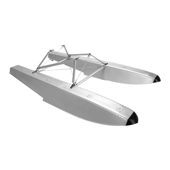
1/4-Scale Floats
Specifications
Length ....................................................................................................................................47.625 in (1210mm)
Overall Width of Float Assembly ................................................................................................27.25 in (692mm)
Tip of Float to the Step ...............................................................................................................25.25 in (641mm)
Approximate Weight of Each Float Less Rudder Servo ..................................................................................30 oz
Scale Struts Weight .....................................................................................................................................15.4 oz
Total Weight ......................................................................................................................................... 75 to 80 oz
For Models Weighing .....................................................................................................................12.0 to 18.0 lb
www.modellmarkt24.ch
www.modellmarkt24.ch
ASSEMBLY MANUAL
Advertisement
Table of Contents

Subscribe to Our Youtube Channel
Related Manuals for Horizon Hobby Hangar 9


Summary of Contents for Horizon Hobby Hangar 9
- Page 1 1/4-Scale Floats ASSEMBLY MANUAL Specifications Length ............................47.625 in (1210mm) Overall Width of Float Assembly ....................27.25 in (692mm) Tip of Float to the Step .......................25.25 in (641mm) Approximate Weight of Each Float Less Rudder Servo ..................30 oz Scale Struts Weight .............................15.4 oz Total Weight ............................
- Page 2 Table of Contents Using the Manual ..............2 Required Tools and Adhesives .
-
Page 3: Required Tools And Adhesives
Hangar 9, E-flite and Align. You’ll be able to fly aircraft that are only available on FS One such as the T-REX, Blade CX2, Blade CP Pro, Hangar 9 P-51 and F-22 PTS. -
Page 4: Warranty Period
Warranty Period Exclusive Warranty- Horizon Hobby, Inc., (Horizon) warranties that the Products purchased (the "Product") will be free from defects in materials and workmanship at the date of purchase by the Purchaser. Limited Warranty (a) This warranty is limited to the original Purchaser ("Purchaser") and is not transferable. REPAIR OR REPLACEMENT AS PROVIDED UNDER THIS WARRANTY IS THE EXCLUSIVE REMEDY OF THE PURCHASER. -
Page 5: Inspection Or Repairs
To receive warranty service, you must include your original sales receipt verifying the proof-of-purchase date. Provided warranty conditions have been met, your Product will be repaired or replaced free of charge. Repair or replacement decisions are at the sole discretion of Horizon Hobby. Non-Warranty Repairs... -
Page 6: Contents Of Kit
Safety, Precautions and Warnings This model is controlled by a radio signal that is subject to interference from many sources outside your control. This interference can cause momentary loss of control so it is advisable to always keep a safe distance in all directions around your model, as this margin will help to avoid collisions or injury. -
Page 7: Float Assembly
Float Assembly oo Required Parts Step 2 • Float (right and left) • Servo hatch (2) Apply a bead of silicone sealer around the edge of the • Strut bracket (4) • Rubber boot (2) servo hatch. Tape the hatch tightly against the float. The silicone will create a gasket that will seal the opening after •... - Page 8 Step 6 Step 8 Insert the Z-bend from the 27 -inch (700mm) Use two 4-40 x 1/2-inch socket head bolts to attach rudder pushrod into the rudder tiller arm from the the rudder to the float. Use a small amount of silicone bottom as shown.
- Page 9 Note: Make sure to use threadlock on the Step 910Use a pin drill and 5/64-inch (2mm) drill screw to prevent it from vibrating loose. bit to enlarge the outer hole of a standard servo arm. Slide the brass pushrod connector into the hole and secure it ...
- Page 10 Step 14 Step 15 Slide the cross brace into the opening on the side of the Install the rear cross brace following the same procedure float. Check that the holes in the float align with the brace, as the previous step. as there is a front and rear brace and the holes do not match.
- Page 11 Step 17 Step 19 Remove the strut end fitting from one end of the Use four 4-40 x 1/2-inch socket head screws to attach preassembled 19 -inch (489mm) wire braces. Slide a the wire braces between the cross braces. Once the wire 1/4-inch (6mm) piece of fuel tubing onto the wire.
- Page 12 Step 21 Step 22 Adjust the strut end fittings so the distance between Use a 8-32 x 3/4-inch socket head bolt w/shoulder, 8-32 the center of the screw heads will measure 11 -inch locknut and two #8 nylon washers to attach the 7 -inch (284mm) as shown.
- Page 13 Step 23 Step 25 Remove the strut end fitting from one end of the Use a 8-32 x 3/4-inch socket head bolt w/shoulder, 8-32 preassembled 11-inch (280mm) wire braces. Slide a locknut and two #8 nylon washers to attach the 8 -inch 1/4-inch (6mm) piece of fuel tubing onto the wire.
- Page 14 Step 26 Step 27 Thread a 4-40 nut onto the threaded end of the cross Attach the diagonal brace using a 4-40 x 3/8 socket head member. The distance from the center of the hole to the bolt. Leave the screw loose until the floats have been end of the nut is 15 -inch (384mm).
-
Page 15: Float Installation
Float Installation Required Parts Step 2 • 8-32 x 3/4-inch socket head bolt You will need to prepare for the connection of the standard thread (8) water rudder servos at this time. There are two options, • 8-32 x 3/4- inch socket head bolt w/shoulder (4) depending on if you are using a computer radio and plan on using mixing or not: •... - Page 16 Step 4 Step 5 With the fuselage inverted, use two 8-32 x 3/4-inch socket Use two 8-32 x 3/4-inch socket head bolts, four nylon head bolts, four nylon washers and two 8-32 locknuts to washers and two 8-32 locknuts to attach the rear bracing attach the front bracing to the float mounting brackets on to the float mounting brackets on the fuselage.
-
Page 17: Recommended Center Of Gravity (Cg)
Stick-on weights are available at your local hobby store and work well for this purpose. The Hangar 9 J-3 Cub will typically need the addition of 2–3 ounces per float. To do this you can use our HAN3626 lead weight strips (temporarily add these to the top of the floats until you have acheived the proper balance). -
Page 18: Official Ama National Model Aircraft Safety Code
2008 Official AMA National Model Aircraft Safety Code GENERAL 8. I will not operate model aircraft carrying pyrotechnic devices which explode burn, or propel a projectile 1. A model aircraft shall be defined as a non-human- of any kind. Exceptions include Free Flight fuses or carrying device capable of sustained flight in the devices that burn producing smoke and are securely atmosphere. -
Page 19: Official Ama National Model Aircraft Safety Code
2008 Official AMA National Model Aircraft Safety Code Radio Control 7. With the exception of events flown under official AMA rules, no powered model may be flown outdoors closer 1. All model flying shall be conducted in a manner to than 25 feet to any individual, except for the pilot and avoid over flight of unprotected people. -
Page 20: Instructions For Disposal Of Weee By
© 2008 Horizon Hobby, Inc. 4105 Fieldstone Road Champaign, Illinois 61822 (877) 504-0233 horizonhobby.com...
Need help?
Do you have a question about the Hangar 9 and is the answer not in the manual?
Questions and answers