Sony CFS-E2 Service Manual
Radio cassette-corder
Hide thumbs
Also See for CFS-E2:
- Operating instructions (4 pages) ,
- Specifications (2 pages) ,
- Operating instructions (2 pages)
Table of Contents
Advertisement
Quick Links
SERVICE MANUAL
Ver 1.3 2002. 08
• Frequency range
FM : 87.6 – 108 MHz/AM : 530 – 1,710 kHz
FM : 87.6 – 107 MHz/AM : 531 – 1,602 kHz (AEP)
• Antennas FM : Telescope/AM : Built-in ferrite bar
• Recording system 4-track, 2-channel stereo
• Frequency response 100-10,000 Hz
• Speakers Full-range : 5.7 cm (2
• Output Headphones jack (stereo minijack), for 8-32 ohm
impedance headphones
• Power output 1 W+1 W (at 10% harmonic distortion in
DC operation)
• Battery life
FM recording
Sony SUM-3 (NS) : Approx. 2 hours
Sony AM3 (N) alkaline:Approx. 5 hours
playback
Sony SUM-3 (NS) : Approx.1.5 hours
Sony AM3 (N) alkaline:Approx. 4 hours
Sony Corporation
9-923-263-14
2002H1600-1
Personal Audio Company
© 2002.08
Published by Sony Engineering Corporation
SPECIFICATIONS
(US, Canadian, Taiwan)
1
/
inches) dia, cone type
4
CFS-E2
Model Name Using Similar Mechanism
Tape Transport Mechanism Type
• Power requirements 120V AC, 60Hz (US, Canadian, Taiwan)/
220V AC, 50/60Hz (AEP)/ 6V DC, four size
AA (R6) batteries
• Power consumption DC 4 W
• Dimensions Approx. 285 × 101 × 58 mm (w/h/d)
× 4 × 2
1
3
(11
/
/
inchs)incl. projecting parts and controls
4
8
• Mass Applox. 720 g (1 lb 94 oz)(incl.batteries)
• Supplied accessory AC power adaptor(1)
Design and specifications are subject to change without notice.
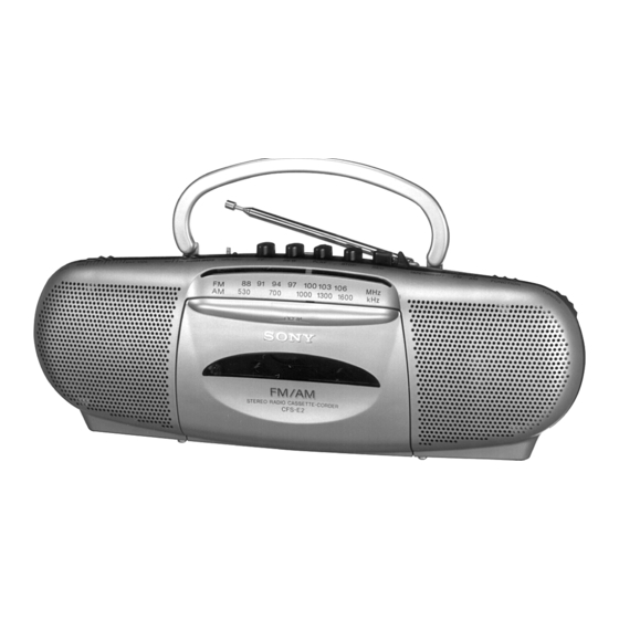
RADIO CASSETTE-CORDER
US Model
Canadian Model
AEP Model
Taiwan Model
NEW
MF-E2
Advertisement
Table of Contents

Related Manuals for Sony CFS-E2


Summary of Contents for Sony CFS-E2
- Page 1 • Power output 1 W+1 W (at 10% harmonic distortion in DC operation) • Battery life FM recording Sony SUM-3 (NS) : Approx. 2 hours Sony AM3 (N) alkaline:Approx. 5 hours playback Sony SUM-3 (NS) : Approx.1.5 hours Sony AM3 (N) alkaline:Approx. 4 hours...
- Page 2 CRITIQUES POUR LA SÉCURITÉ DE FONCTIONNEMENT. NE COMPONENTS WITH SONY PARTS WHOSE PART NUMBERS REMPLACER CES COMPOSANTS QUE PAR DES PIÈSES SONY APPEAR AS SHOWN IN THIS MANUAL OR IN SUPPLEMENTS DONT LES NUMÉROS SONT DONNÉS DANS CE MANUEL OU PUBLISHED BY SONY.
- Page 3 — 3 —...
- Page 4 SECTION 2 DISASSEMBLY Note : Follow the disassembly procedure in the numerical order given. 2-1. REAR CABINET 1 Four screws (+ BVTP 3 × 24) 3 Connector (CN305) 4 Connector (CN1) 2 Unlock the claw by pressing here. 2-2. MAIN BOARD 2 Connector (CN304) 1 Two screws (+P 2.6 ×...
-
Page 5: General
SECTION 3 SECTION 4 MECHANICAL ADJUSTMENTS ELECTRICAL ADJUSTMENTS PRECAUTION 4-1. TAPE RECODER SECTION 0 dB = 0.775 V • Clean the following parts with a denatured-alchool-moistened swab: PRECAUTION record/playback head Adjustments should be performed in the order given. (Generally erase head playback circuit adjustments should be completed before pinch rollers preforming recording circuit adjustments.) -
Page 6: Tuner Section
4-2. TUNER SECTION 0 dB = 1 µV Tape Speed Adjustment Procedure: Mode : FWD playback • AM section FUNCTION : RADIO BAND : AM Adjustment Value : normal tape speed DECK Frequency counter 2,980 to 3,020 Hz • FM section FUNCTION : RADIO Confirm that the frequency difference between the tape top and... - Page 7 CFS-E2 Ver 1.2 2001. 04 FM Separation Adjustment ) : AEP model Adjustment method: AM Frequency Coverage Adjustment FUNCTION switch ⋅⋅⋅⋅⋅ FM Make adjustment unit the level meter defection is maximized. 520kHz (520kHz) 1,710kHz (1,680kHz) AM Tracking Adjustment Make adjustment unit the level meter defection is maximized.
- Page 8 CFS-E2 SECTION 5 Ver 1.2 2001. 04 DIAGRAM 5-1. PRIINTED WIRNG BOARD DRY BATTERY SIZE "AA" (IEC DESIGNATION R6) SP901 SP902 4PCS,3V TELESCOPIC MAIN BOARD ANTENNA ANT1 M901 REEL CAPSTAN C901 S302 MOTOR S902 MD POWER L601 IC101 C102 ANT2...
-
Page 9: Schematic Diagram — Audio Section
CFS-E2 Ver 1.2 2001. 04 5-2. SCHEMATIC DIAGRAM — AUDIO SECTION — TAPE — 11 — — 12 — — 13 —... -
Page 10: Schematic Diagram — Tuner Section
CFS-E2 Ver 1.2 2001. 04 5-3. SCHEMATIC DIAGRAM — TUNER SECTION — ANT2, CT1 L1, CT2 L2, CT3 T1, CT4 AM TRACKING FM TRACKING FM FREQUENCY AM FREQUENCY ADJUSTMENT ADJUSTMENT COVERAGE COVERAGE ADJUSTMENT ADJUSTMENT MONO STEREO TAPE OFF US,CND. CND : Canadian TW : Taiwan —... -
Page 11: Ic Block Diagrams
5-4. IC BLOCK DIAGRAMS CXA1538N IC601 MM1038BFF IC101, IC201 MM1315BD — 16 —... -
Page 12: Front Cabinet Section
Ver 1.2 2001. 04 SECTION 6 EXPLODED VIEWS NOTE: • -XX, -X mean standardized parts, so they may • The mechanical parts with no reference number When indicating parts by reference number, have some differences from the original one. in the exploded views are not supplied. please include the board name. -
Page 13: Rear Cabinet Section
Ver 1.2 2001. 04 6-2. REAR CABINET SECTION SP901 MIC901 ANT2 SP902 Ref. No. Part No. Description Remarks Ref. No. Part No. Description Remarks 3-011-923-01 POINTER * 72 1-666-350-11 JACK BOARD 3-011-931-01 SPRING (CASSETTE UP) 3-011-907-21 CABINET (REAR) (SILVER) 3-011-908-12 CHASSIS, SPEAKER 3-011-907-31 CABINET (REAR) (BLUE) (US, AEP, Taiwan) 3-229-057-01 HOLDER(MICROPHONE) 3-011-907-41 CABINET (REAR) (RED) (AEP) - Page 14 6-3. MECHANISM DECK-1 (MF-E2) not supplied HRP901 not supplied M901 not supplied not supplied S902 supplied not supplied Ref. No. Part No. Description Remarks Ref. No. Part No. Description Remarks 3-014-809-01 FW ASSY 3-014-808-01 SPRING 3-381-880-01 BELT 3-381-860-01 PINCH ROLLER 3-905-683-01 SPRING 3-381-850-01 ARM (PINCH) (F) 3-381-878-01 SPRING (AZIMUTH)
- Page 15 Ver 1.3 2002.08 6-4. MECHANISM DECK-2 (MF-E2) not supplied supplied not supplied Ref. No. Part No. Description Remarks Ref. No. Part No. Description Remarks 3-934-901-01 LEVER (STOP) 3-381-841-01 GEAR (CAM) 3-905-686-01 LEVER (PLAY) 3-381-885-01 BUSHING 3-381-854-01 LEVER (REW) 3-934-907-01 WASHER (UPPER LOWER) 3-381-853-01 LEVER (FF) 3-934-899-01 GEAR (TU) 3-381-866-01 SPRING (FR LEVER)
-
Page 16: Electrical Parts List
Ver 1.2 2001. 04 SECTION 7 JACK MAIN ELECTRICAL PARTS LIST NOTE: • Due to standardization, replacements in the • RESISTORS When indicating parts by reference number, parts list may be different from the parts All resistors are in ohms. please include the board name. - Page 17 Ver 1.2 2001. 04 MAIN Ref. No. Part No. Description Remarks Ref. No. Part No. Description Remarks C213 1-161-057-00 CERAMIC 0.033uF < DIODE > C214 1-136-167-00 FILM 0.15uF C215 1-136-167-00 FILM 0.15uF 8-719-911-19 DIODE 1SS119-25 C215 1-162-219-31 CERAMIC 68PF 8-719-911-19 DIODE 1SS119-25 C301 1-126-961-11 ELECT 2.2uF...
- Page 18 Ver 1.2 2001. 04 MAIN Ref. No. Part No. Description Remarks Ref. No. Part No. Description Remarks R203 1-247-843-11 CARBON 3.3K 1/4W < TRANSFORMER > R204 1-249-434-11 CARBON 1/4W R205 1-249-429-11 CARBON 1/4W 1-406-040-00 COIL (OSC) R209 1-247-843-11 CARBON 3.3K 1/4W 1-416-155-11 COIL (455kHz IFT) R210...
- Page 19 CFS-E2 Printing Method for Large Sized Documents Such As Circuit Diagrams Printing the page that exceeds A4-size two pages (or letter size) is possible by specifying the print range. (Acrobat Reader Version 4.0 or later) 1. The enlarged print is made, if a smaller range than A4 size is specified and the A4 size is selected as a print paper.
- Page 20 CFS-E2 MEMO — 25 —...
- Page 21 CFS-E2 REVISION HISTORY Clicking the version allows you to jump to the revised page. Also, clicking the version at the upper right on the revised page allows you to jump to the next revised page. Ver. Date Description of Revision 1998.04...
Need help?
Do you have a question about the CFS-E2 and is the answer not in the manual?
Questions and answers