Advertisement
Quick Links
Advertisement

Related Manuals for Manzano Laser Works deHavilland DHC-1 Chipmunk


Summary of Contents for Manzano Laser Works deHavilland DHC-1 Chipmunk
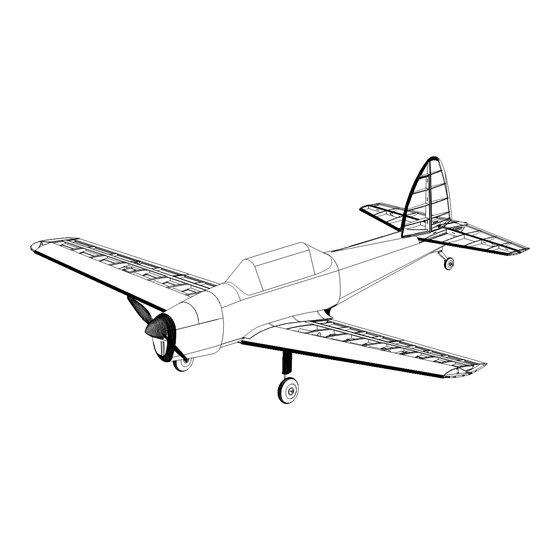
- Page 1 DHC-1 Chipmunk Assembly Guide Manzano Laser Works...
- Page 2 The Manzano de Havilland DHC-1 Chipmunk is based on a design developed by Ivan Pettigrew. The structural design has been updated to take advantage of laser cut parts and to help reduce the build time. Construction of this model can be in any order preferred, but this assembly guide has been organized to follow a suggested build sequence.
- Page 11 TAIL SURFACES ASSEMBLY...
- Page 12 With the stab assembly lined up over the plan, dry fit the leading edges to the r bs. They will lie flat on the rib tabs. The nose of each rib fits in the leading edge notches. When everything is properly aligned apply glue to all joints.
- Page 13 Glue the fin leading edge pieces F2 and F3 together. Place the fin leading edge on the ribs making sure the nose of each rib is fully Dry fit the fin ribs to the fin spar. Place the assembly over the seated in the notches.
- Page 14 WING ASSEMBLY...
- Page 15 Note that W7A and W7B are together in the same spar slot Layout one set of ribs W2 through W11 and one of the 1/8" balsa The wing assembly begins by laying a 36" strip of 1/8" square sheet wing spars. Slide the ribs through their corresponding balsa over one side of the wing plan in the location shown on the Glue the 1/16"...
- Page 16 Place a piece of 1/8" diameter piano wire next to the first lamination before gluing the second lamination. Remove the piano wire when both top lamination pieces are in place. Remove the structure from the building board. Sand the top and bottom edges of the sub leading edge and trailing edges so they match the contour of the ribs.
- Page 18 Make up the four servo trays using the 1/32" plywood and 1/16" Place the landing gear legs into the slots of the landing gear balsa tray laminations. The flap and aileorn trays are different in mounting blocks. Place a plywood retaining lug in the pockets of size so be sure to match the appropriate part pairs.
- Page 19 FUSELAGE ASSEMBLY...
- Page 20 Fuselage assembly begins with the internal liteply box. Add the bottom internal box piece that fits behind 7B. Install the top, side, forward, and rear formers. These are a Assemble the sides, top pieces, and formers 3B, 4B, and 7B. combination of balsa, plywood, and liteply parts.
- Page 21 Assembly of the rear fuselage begins by gluing the 1/8" balsa The horizontal 1/8" balsa keel pieces are glued in place after the Glue the rear fuselage formers to the keel parts. Use the slots in vertical keel parts together. vertical pieces are glued together.
- Page 22 Solder Clevis Elevator Rudder Threaded Clevis From the forward side of former 12, slide a 16" length of pushrod Servo End sleeve under the horizontal keel piece through the hole in former Install the servo rails and then the servos. The servo rails are 12.
- Page 23 Note: There are 2 The fuselage is covered with 1/16" balsa sheet. Patterns have C2T formers Mark Here been provided on the plan to help cut each sheet section to the proper size and shape. Making up paper patterns before cutting any balsa is a good idea to help make sure the pieces will fit the target section properly.
- Page 24 FINAL STRUCTURAL ASSEMBLY...
- Page 25 The area between the fillet shape formers is filled with balsa and Before covering the model there are a few final assembly steps light weight spackle. When the spackle is fully dry sand it to to perform. They begin with the installation of the wing fillets. shape using the shape formers as a guide.
- Page 26 Dry fit the stab top center section sheeting piece to the stab. Slide the fin spar base through the cutout in the top and bottom stab sheeting. With the fin resting on the stab check the alignment to be sure the fin is vertical and the fin center line is aligned with the fuselage center line.
Need help?
Do you have a question about the deHavilland DHC-1 Chipmunk and is the answer not in the manual?
Questions and answers