Table of Contents
Advertisement
QQ
3 7 63 1515 0
SERVICE MANUAL
Ver 1.1 2000. 08
Manufactured under license from Dolby Laboratories
Licensing Corporation.
"DOLBY" and the double-D symbol a are trademarks
of Dolby Laboratories Licensing Corporation.
TE
L 13942296513
Radio section
Frequency range
Tape section
Frequency response
(Dolby NR off)
(EIAJ)
Output
Input
General
Power requirements
www
.
MICROFILM
http://www.xiaoyu163.com
FM : 76.0 – 90.0 MHz
AM : 531 – 1,710 kHz
Playback: 40 – 15,000 Hz
Recording/playback: 100 – 8,000 Hz
Headphones (2 REMOTE) jack
Load impedance 8 – 300 Ω
Microphone (MIC) jack
Minimum input level 0.4 mV
1.5 V
Rechargeable battery
One R6 (size AA) battery
x
ao
u163
y
i
http://www.xiaoyu163.com
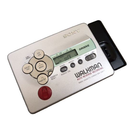
WM-GX677
2 9
8
Model Name Using Similar Mechanism
Tape Transport Mechanism Type
Q Q
3
6 7
1 3
1 5
SPECIFICATIONS
Dimensions (w/h/d)
Mass
Accessories
Design and specifications are subject to change without notice
RADIO CASSETTE CORDER
co
.
9 4
2 8
Tourist Model
WM-GX670/GX674
MF-WMGX670-162
0 5
8
2 9
9 4
2 8
Approx. 108.4 × 77.7 × 23.8 mm
× 3
×
(4
3
/
1
/
15
/
inches), incl.
8
8
16
projecting parts and controls
Approx. 150 g (5.3 oz)
Approx. 215 g (7.6 oz) incl.
rechargeable battery and a cassette
Battery charger
Battery case
Stereo earphones with remote control
Carrying pouch
Rechargeable battery carring case
Stereo microphone
Instruction manual
m
9 9
9 9
Advertisement
Table of Contents

Related Manuals for Sony WM-GX677


Summary of Contents for Sony WM-GX677
- Page 1 WM-GX677 3 7 63 1515 0 SERVICE MANUAL Tourist Model Ver 1.1 2000. 08 Manufactured under license from Dolby Laboratories Model Name Using Similar Mechanism WM-GX670/GX674 Licensing Corporation. Tape Transport Mechanism Type MF-WMGX670-162 “DOLBY” and the double-D symbol a are trademarks of Dolby Laboratories Licensing Corporation.
- Page 2 LIST ARE CRITICAL TO SAFE OPERATION. REPLACE THESE circuit board (within 3 times). COMPONENTS WITH SONY PARTS WHOSE PART NUMBERS • Be careful not to apply force on the conductor when soldering APPEAR AS SHOWN IN THIS MANUAL OR IN SUPPLEMENTS or unsoldering.
-
Page 3: Service Note
Rotation of the idler gear (A) (S side) is detected using the photo- Connect square wave or sine wave to resistor (R43). (See reflector (PH1) in the WM-GX677. PH1 is located on the MAIN illustration below.) board, therefore the rotation of the idler gear (A) (S side) cannot be Press the p switch (S3) to enter the STOP mode. - Page 4 http://www.xiaoyu163.com 3 7 63 1515 0 [ Slider (NR) ] [ Tape drive mechanism ] Tape drive mechanism in PLAY mode Gear (NR) (FWD : Left side REV : Right side) Idler Gear Idler Gear (A)(S side) Slider (NR) (A)(T side) Gear Gear (REEL)(S side) (REEL)(T side)
-
Page 5: General
http://www.xiaoyu163.com SECTION 2 GENERAL This section is extracted 3 7 63 1515 0 from instruction manual. • LOCATION OF CONTROLS 1 OPEN knob 2 FF • AMS/REW• AMS button 3 2 REMOTE jack 4 MIC (PLUG IN POWER) jack 5 ISS (1, 2, 3) knob 6 ∑... -
Page 6: Case Block Assembly
http://www.xiaoyu163.com SECTION 3 DISASSEMBLY 3 7 63 1515 0 Note : Disassemble the unit in the order as shown below. Case block Reel ornament Cassette lid assembly Main board assembly assembly Motor Holder Pinch lever (N)/(R) Magnetic head Belt (F2) (M601) assembly assembly... -
Page 7: Belt (F2)
http://www.xiaoyu163.com 3 7 63 1515 0 3-2. BELT (F2) 3 Belt (F2) 2 Terminal board (Battery ’ ) Belt threading Belt (F2) 1 Remove solder from the battery terminal board. L 13942296513 3-3. CASSETTE LID ASSEMBLY 5 Cassette lid assembly 2 Two screws (M1.4 ×... -
Page 8: Reel Ornament Assembly
http://www.xiaoyu163.com 3 7 63 1515 0 3-4. REEL ORNAMENT ASSEMBLY 1 Reel Ornament assembly Remove the assembly while removing Note: the three claws and boss carefully. Claw Claw L 13942296513 3-5. MAIN BOARD 6 Screw (B1.7 × 3) 8 Remove soldeing tapping 2 Screw (M1.4) (two points) -
Page 9: Motor (M601)
http://www.xiaoyu163.com 3 7 63 1515 0 3-6. MOTOR (M601) 1 Two screws (M1.4) Toothed lock 2 Motor (M601) L 13942296513 3-7. HOLDER ASSEMBLY 4 Screw (M1.4) 7 Cassette bracket assembly 5 Lock lever (S) 8 Flexible board 2 Shaft 9 Remove the holder assembly in the direction of the arrow. -
Page 10: Pinch Lever (N)/(R) Assembly
http://www.xiaoyu163.com 3 7 63 1515 0 3-8. PINCH LEVER (N) / (R) ASSEMBLY Claw 2 Remove the pinch lever (N) assembly in the direction of the arrow. Claw Note: Be careful of the claw 1 Remove the pinch lever (R) assembly in the direction of the arrow. -
Page 11: Electrical Adjustment
http://www.xiaoyu163.com SECTION 4 SECTION 5 MECHANICAL ADJUSTMENT ELECTRICAL ADJUSTMENT 3 7 63 1515 0 PRECAUTION PRECAUTION Clean the following parts with a denatured-alcohol-moistened Specified voltage: 1.3 V (DC) swab: Switch and control position record/playback/erase head pinch roller MENU switch rubber belts capstan HOLD : OFF... - Page 12 http://www.xiaoyu163.com 3 7 63 1515 0 FM VCO Adjustment TUNER SECTION 0dB=1µV Procedure : FM RF signal [AM] generator BAND switch : AM 0.01 µ F AM RF signal to ANT (TP1) generator Put the lead-wire antenna close to Carrier frequency : 98MHz the set.
-
Page 13: Block Diagram
WM-GX677 SECTION 6 DIAGRAMS 3 7 6 3 1 5 1 5 0 6-1. BLOCK DIAGRAM 1 3 9 4 2 2 9 6 5 1 3 TUME TUME w w w u 1 6 3 — 13 —... -
Page 14: Printed Wiring Board
WM-GX677 6-2. PRINTED WIRING BOARD 3 7 6 3 1 5 1 5 0 1 3 9 4 2 2 9 6 5 1 3 • Semiconductor Location Ref. No. Location Ref. No. Location Ref. No. Location Ref. No. Location Ref. -
Page 15: Schematic Diagram (1/2)
http://www.xiaoyu163.com WM-GX670/GX674 3 7 6 3 1 5 1 5 0 Note • Voltages are taken with a VOM (Input impedance 10 MΩ). • All capacitors are in µF unless otherwise noted. pF: µµF Voltage variations may be noted due to normal produc- 50 WV or less are not indicated except for electrolytics tion tolerances. - Page 16 http://www.xiaoyu163.com WM-GX670/GX674 6-4. SCHEMATIC DIAGRAM (2/2) 3 7 6 3 1 5 1 5 0 1 3 9 4 2 2 9 6 5 1 3 • Waveform Note • All capacitors are in µF unless otherwise noted. pF: µµF no mark : REC/PLAY IC3 &¢...
-
Page 17: Ic Block Diagrams
http://www.xiaoyu163.com 3 7 63 1515 0 6-5. IC BLOCK DIAGRAMS TA7371AF-EL IC501 LA3235W SYSTEM CONTROL N.C. VCC2 MIC IN L V REF NF L V REF RADIO IN L REV REC L MIC IN R REV REC R NF R FWD REC R RADIO IN R FWD REC L... - Page 18 http://www.xiaoyu163.com 3 7 63 1515 0 IC301 TA2123AF (EL) 36 35 – RF IN PW GND – OUT B PW B OUT C C-AMP SW 37 MT TC PW A PW C OUT A – BEEP 39 BEEP AMS OUT 40 RIPPLE BASE FILTER...
- Page 19 http://www.xiaoyu163.com 3 7 63 1515 0 6-6. IC PIN FUNCTION DESCRIPTION • IC3 TC9327AF-604 Pin No. Pin Name Description COM 1 to 1 to 4 Common terminal. COM 4 5 to 22 S1 to S18 Segment output terminal. DOLBY VCC Dolby control terminal.
- Page 20 http://www.xiaoyu163.com 3 7 63 1515 0 Pin No. Pin Name Description MOTOR DIR MOTOR control terminal. TAPE TAPE detect terminal. (L: ON, H: OFF) REC CTL REC circuit control output. AVLS CTL Terminal for controlling AVLS (when ON=H). BST CTL Tone control terminal (L: normal, Hi-imp: MEGA BASS).
-
Page 21: Cabinet Block, Main Board
http://www.xiaoyu163.com Ver 1.1 2000.08 SECTION 7 EXPLODED VIEWS 3 7 63 1515 0 NOTE: • -XX, -X mean standardized parts, so they may • The mechanical parts with no reference number have some differences from the original one. in the exploded views are not supplied. •... -
Page 22: Mechanism Deck Block
http://www.xiaoyu163.com 3 7 63 1515 0 7-2. MECHANISM DECK BLOCK (MF-WMGX670-162) M601 PM901 L 13942296513 HP901 Ref. No. Part No. Description Remarks Ref. No. Part No. Description Remarks X-3376-293-1 HOLDER (F) ASSY 3-007-433-01 SHEET (N), REFLECTION X-3377-228-1 LEVER (R) ASSY, PINCH X-3376-291-1 CHASSIS ASSY (F) 3-029-271-01 SPRING (HD) 3-010-274-02 TABLE, REEL... -
Page 23: Electrical Parts List
http://www.xiaoyu163.com SECTION 8 MAIN ELECTRICAL PARTS LIST 3 7 63 1515 0 NOTE: • Due to standardization, replacements in the • CAPACITORS: • SEMICONDUCTORS parts list may be different from the parts uF: µF In each case, u: µ, for example: specified in the diagrams or the components •... - Page 24 http://www.xiaoyu163.com MAIN 3 7 63 1515 0 Ref. No. Part No. Description Remarks Ref. No. Part No. Description Remarks C210 1-164-677-11 CERAMIC CHIP 0.033uF C536 1-115-156-11 CERAMIC CHIP C211 1-164-227-11 CERAMIC CHIP 0.022uF C537 1-115-156-11 CERAMIC CHIP C301 1-119-663-11 TANTAL. CHIP 47uF 2.5V C538...
- Page 25 http://www.xiaoyu163.com MAIN 3 7 63 1515 0 Ref. No. Part No. Description Remarks Ref. No. Part No. Description Remarks < FERRITE BEAD > < TRANSISTOR > 1-500-445-21 FERRITE 8-729-037-89 TRANSISTOR 2SC4627J-C(TX).SO 1-500-445-21 FERRITE 8-729-028-69 TRANSISTOR 2SC4655-BC(TX) 1-500-445-21 FERRITE 8-729-037-89 TRANSISTOR 2SC4627J-C(TX).SO 1-500-245-11 FERRITE 8-729-037-89 TRANSISTOR 2SC4627J-C(TX).SO 1-410-997-42 INDUCTOR CHIP 2.2uH...
- Page 26 http://www.xiaoyu163.com MAIN 3 7 63 1515 0 Ref. No. Part No. Description Remarks Ref. No. Part No. Description Remarks < RESISTOR > 1-218-875-11 RES, CHIP 0.50% 1/16W 1-218-875-11 RES, CHIP 0.50% 1/16W 1-216-841-11 METAL CHIP 1/16W 1-216-833-11 RES, CHIP 1/16W 1-216-823-11 METAL CHIP 1.5K 1/16W...
- Page 27 http://www.xiaoyu163.com MAIN 3 7 63 1515 0 Ref. No. Part No. Description Remarks Ref. No. Part No. Description Remarks R504 1-216-789-11 METAL CHIP 1/16W 1-771-053-21 SWITCH, KEY BOARD (MENU) R505 1-216-835-11 METAL CHIP 1/16W 1-771-053-21 SWITCH, KEY BOARD (SET) R506 1-216-835-11 METAL CHIP 1/16W 1-771-053-21 SWITCH, KEY BOARD (BAND)
- Page 28 WM-GX677 3 7 63 1515 0 L 13942296513 u163 Sony Corporation 99C1670031-1 Printed in Singapore ©1999.3 Personal A&V Products Company 9-926-957-11 Published by Quality Engineering Dept. — 36 — (Shinagawa) http://www.xiaoyu163.com...
Need help?
Do you have a question about the WM-GX677 and is the answer not in the manual?
Questions and answers