Table of Contents
Advertisement
Advertisement
Table of Contents

Subscribe to Our Youtube Channel
Related Manuals for Stryker Crossfire


Summary of Contents for Stryker Crossfire
- Page 1 Crossfire™ Console REF 0475000000 User Guide...
- Page 3 Warnings and Cautions ..............3 Product Description and Intended Use ......7 Indications/Contraindications ............8 Package Contents ................8 Available Accessories ................8 The Crossfire™ Console ..............9 Setup and Interconnection ............11 Electromagnetic Compatibility ............11 Connections ..................16 Powering the Console On and Off ...........18 Operation ..................19 The Crossfire™...
-
Page 5: Warnings And Cautions
Install this device in an operating room that complies with all applicable IEC, CEC, and NEC requirements for safety of electrical devices. DO NOT use the Crossfire™ system on patients with cardiac pacemakers or other electronic device implants. Doing so could lead to electromagnetic interference and possible death. - Page 6 The operator of the Crossfire™ system should be sure that the system functions as outlined in this manual prior to a surgical procedure. The Crossfire™ system was fully tested at the factory before shipment.
- Page 7 The use of antistatic sheeting is recommended for this purpose. DO NOT activate the Crossfire™ system for prolonged lengths of time when the attachment is not in contact with tissue. Doing so may lead to unintentional damage to surrounding tissue.
- Page 8 DO NOT remove the cover of the console as this could cause electric shock and product damage. Attempt no internal repairs or adjustments, unless specified otherwise in this manual. Units requiring repair should be returned to Stryker. Disconnect the Crossfire™ system from the electrical output when inspecting fuses.
-
Page 9: Product Description And Intended Use
The Crossfire™ Integrated Arthroscopy System is a combination powered shaver system/electrosurgical generator, intended for use in arthroscopic and orthopedic procedures. Illustrated below, the Crossfire™ system consists of the following components: 1. Crossfire™ Console • Acts as a connection hub for the various components of the Crossfire™ system... -
Page 10: Indications/Contraindications
Indications/Contraindications The Crossfire™ system is indicated for use in orthopedic and arthroscopic procedures for the knee, shoulder, ankle, elbow, wrist, and hip. The Crossfire™ System provides abrasion, resection, debridement, and removal of bone and soft tissue through its shaver blade, and the ablation and coagulation of soft tissue, as well as hemostasis of blood vessels, through its electrosurgical probe. -
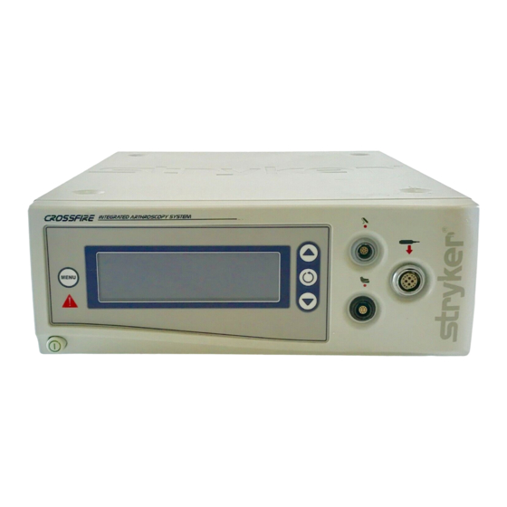
Page 11: The Crossfire™ Console
The Crossfire™ Console The Crossfire™ console is the connection hub for the components of the Crossfire™ system. It generates RF energy, powers motorized shavers, and provides user controls and system feedback. Front Panel The front console panel features ports for connecting handpieces, controls for adjusting handpiece settings, and an LCD screen to provide system feedback. - Page 12 Rear Panel The rear panel provides ports for connecting the console to other Stryker equipment. 1. Firewire Connectors Enables connection to other Stryker Firewire devices, such as the iSWITCH Universal Wireless Footswitch 2. USB Drive Enables uploading of preset user settings 3.
-
Page 13: Setup And Interconnection
To ensure electromagnetic compatibility (EMC), the Crossfire™ System must be installed and operated according to the EMC information provided in this manual. The Crossfire™ System has been designed and tested to comply with IEC 60601- 1-2 requirements for EMC with other devices. Warning This equipment is intended for use by health care professionals only. - Page 14 Guidance and Manufacturer’s Declaration: Electromagnetic Emissions The Crossfire™ System is intended for use in the electromagnetic environment specified below. The customer or the user of Crossfire™ System should ensure that it is used in such an environment. Emissions Test Compliance...
- Page 15 Guidance and Manufacturer’s Declaration: Electromagnetic Immunity The Crossfire™ System is intended for use in the electromagnetic environment specified below. The customer or the user of Crossfire™ System should ensure that it is used in such an environment Immunity Test IEC 60601 Test Level...
- Page 16 Guidance and Manufacturer’s Declaration: Electromagnetic Immunity Crossfire™ System is intended for use in the electromagnetic environment specified below. The customer or the user of Crossfire™ System should ensure that it is used in such an environment. Immunity Test IEC 60601 Test...
- Page 17 Recommended Separation Distances Between Portable and Mobile RF Communications Equipment and the Crossfire™ System The Crossfire™ System is intended for use in an electromagnetic environment in which radiated RF disturbances are controlled. The user of the Crossfire™ System can help prevent electromagnetic interference by maintaining a minimum distance between portable and mobile RF communications equipment (transmitters) and the Crossfire™...
-
Page 18: Connections
The console and footswitch are not sterile devices and should not enter the sterile field. The Crossfire™ System is compatible only with the Stryker handpieces and footswitches listed in this manual. Do not connect any equipment not specified in this manual, as unexpected results or serious injury will occur. - Page 19 Place the console on a sturdy platform, such as a Stryker cart. • Select a location according to the recommendations in the preceding EMC tables. • Leave four inches of space around all sides for convection cooling. Connect the AC power. Connect the handpieces and footswitch. Connect suction tubing (for all suction-capable devices). EN-17...
-
Page 20: Powering The Console On And Off
Powering the Console On and Off Press the power button to power the console on and off. The button will shine green when the console is on. Warning Should emergency shutdown become necessary, power off the console as described above. As an added safety measure, the console can be separated from the AC power mains by detaching the AC power cord from either end. -
Page 21: Operation
Operation The Crossfire™ interface displays system status, enables you to choose between RF and shaver modes, and enables you to adjust power and speed settings. Activating the actual handpieces is performed through controls on the handpiece and on the Crossfire™ Footswitch. -
Page 22: The Crossfire™ Interface
The Crossfire™ Interface Control Description 1. Menu The Menu button sets user and “Adjusting User and system settings. System Settings” 2. LCD screen The LCD screen displays system “Reading the LCD status, error codes, mode of Screen” operation, cutting speed, and power levels. -
Page 23: Adjusting User And System Settings
User Preference Settings User preferences, such as power and cutting speeds and button assignments for the handpiece and footswitch, can be adjusted through the Crossfire™ interface. Select from the default settings provided with the console, or contact your Stryker representative to customize your own. -
Page 24: System Settings
System Settings System settings, such as screen brightness, contrast, and system sound can be adjusted through the Crossfire™ interface. Press and hold Press to choose (contrast), (brightness), or (sound). Press to adjust. Press and hold to exit. (Note: A short press will display the current version of the console software.) -
Page 25: Reading The Lcd Screen
The LCD screen displays the devices that are connected to the console and their current status. RF Mode In RF mode, the LCD will show: SERFAS 1. Footswitch status Crossfire footswitch connected iSwitch footswitch connected not connected 2. Mode cut mode coagulation mode 3. - Page 26 Shaver Mode In shaver mode, the LCD will show: 9000 MC DISP NAME 1. Footswitch status Crossfire footswitch connected iSWITCH footswitch connected not connected 2. Button response one touch TOUCH (pressing the shaver button once will activate the shaver to a default speed;...
- Page 27 Dual Mode In dual mode, the LCD will show the status of both devices. The shaver status will always appear to the right, except during adjustments to RF settings. To select between RF and shaver modes, press 9000 FIXED Dual mode, normal screen.
-
Page 28: Selecting Between Rf And Shaver Modes
• Press any button on the desired handpiece. Selecting Force Modulation in RF Mode The Crossfire Console features an additional RF mode known as Force Modulation. Force Modulation is an alternative ablation mode that duty cycles RF output at a low frequency to achieve a lower average power output than in normal CUT mode. -
Page 29: Using The Handpiece
Using the Handpiece Warning During use, the RF and shaver handpieces generate electronic noise that may interfere with EKG readings. Before responding to any erratic EKG readings, first power down the system to ensure the readings are not the result of system noise. -
Page 30: Using The Footswitch
Reverse (one-touch) Using the Footswitch The RF and shaver handpieces can also be controlled by the Crossfire™ Footswitch. The default footswitch controls are shown below. To customize button assignments, contact your Stryker representative. Note: For more detailed information on the Crossfire™ Footswitch, consult the Crossfire™... - Page 31 Default RF Controls Button Function (controls are the same for defaults 1, 2, and 3) Decrease Cut Level Select Handpiece: RF or Shaver Increase Cut Level Coag EN-29...
- Page 32 Default Shaver Controls Button Function Default 1 Default 2 / None Default 3 Select Mode: Select Mode: Oscillate or Oscillate or Forward/Reverse Forward/Reverse Select Handpiece: Select Handpiece: Select Handpiece: RF or Shaver RF or Shaver RF or Shaver Select Direction: Select Speed: Select Speed: Forward or Reverse...
- Page 33 Using the iSWITCH™ Wireless Footswitch The Crossfire™ system can be used with the iSWITCH Wireless Footswitch System. Connect the Crossfire™ console to the iSWITCH™ console using one of the Firewire connection ports on each console. Consult the iSWITCH™ Operating and Maintenance Manual (P/N 1000-400-700) for further operation instructions.
-
Page 34: Audible Feedback
Audible Feedback The Crossfire™ Console will provide audible feedback for the following events: Event Signal During system startup System self-test Two-second beep Handpiece connected Single beep Disposable attachment connected Single beep Footswitch detected Single beep RF probe detected Single beep... -
Page 35: Troubleshooting
Troubleshooting Problem Possible Solution Console A hardware fault is • Turn the power off and on again. detected • If the problem persists, contact a Stryker representative or return the console for repair. The AC voltage is • Turn the power off and on again. incorrect • If the problem persists, contact a Stryker representative or return the console for repair. A software default • Turn the power off and on again. - Page 36 Disposable RF probe is not Check the connection to the ready console. Attachments RF probe is expired Replace probe. RF probe Replace probe. identification is invalid RF probe • Check the connection to the communication console. error • If necessary, replace probe. Exceeded time Replace probe usage RF power is too • Check the probe for damage.
-
Page 37: Cleaning And Maintenance
Consult the appropriate user guide for cleaning and reprocessing instructions. Disposable attachments are intended for single use only and should not be cleaned, sterilized, or reused. Maintenance The Crossfire™ console requires no preventative or periodic maintenance. However, Stryker recommends you reboot the system daily for best performance. EN-35... -
Page 38: Disposal
Disposal This product contains electrical waste or electronic equipment. It must not be disposed of as unsorted municipal waste and must be collected separately in accordance with applicable national or institutional related policies relating to obsolete electronic equipment. Dispose of any system accessories according to normal institutional practice relating to potentially contaminated items. -
Page 39: Technical Specifications
Product(s), therefore, may not agree in detail to the published design or specifications. All specifications are subject to change without notice. Please contact the local Stryker Endoscopy distributor or call your local Stryker Endoscopy sales representative or agent for information on changes and new products. - Page 40 Output Power versus Setting at 200ohms Resistive Load Output Power versus Setting at 200 Ohm Load Coag Coag Coag Cut Level Output Power (CUT) versus Load Resistance Output Power (Cut) versus Load Resistance Half Setting Full Setting 1000 Load Resistance (ohms) EN-38...
- Page 41 Output Power (COAG) versus Load Resistance Output Power (Coag) versus Load Resistance Coag 1 Coag 2 Coag 3 1000 Load Resistance (Ohms) Maximum Output Voltage (RMS) versus Setting Maximum Open Circuit Voltage versus Set Point Coag Coag Coag Cut Level EN-39...
- Page 42 This device must accept any interference received, including interference that may cause undesired operation. Note: FCC regulations provide that changes or modifications not expressly approved by Stryker Endoscopy could void your authority to operate this equipment. Frequency of transmission: 13.56MHz Type of frequency / characteristics of the modulation: 10% ASK Subcarrier: 423.75kHz, Manchester coding...
- Page 43 Industry Canada (IC) IC: 4919C-XFC Trade Name: Crossfire™ Console Type or Model: 0475000000 Operation is subject to the following two conditions: (1) this device may not cause interference, and (2) this device must accept any interference, including interference that may cause undesired operation of the device.
-
Page 44: Symbols And Definitions
Indicates risks to the safety of the patient or user. Failure to follow warnings may result in injury to the patient or user. Warning/Caution: See instructions for Hazardous voltage present Front Console Symbols Power Select Down MENU Menu Footswitch Probe Handpiece Rear Console Symbols Equipotentiality Stryker firewire Emits RF radiation EN-42... - Page 45 Type BF rated Protective ground earth Compliant to CSA C22.2 No. Fuse rating 601.1-M90, and UL 601-1 F 16.0AH, 250V UL classified LCD Symbols Electrosurgical unit Contrast Brightness Sound Packaging/Labeling Symbols Legal manufacturer Fragile Date of manufacture Atmospheric pressure range Ambient temperature Relative humidity range range...
- Page 48 Stryker Endoscopy 5900 Optical Court San Jose, CA 95138 USA 1-408-754-2000, 1-800-624-4422 www.stryker.com 1000-401-036 Rev. J 2014/01...
Need help?
Do you have a question about the Crossfire and is the answer not in the manual?
Questions and answers