Table of Contents
Advertisement
Quick Links
Advertisement
Table of Contents

Subscribe to Our Youtube Channel
Related Manuals for SLE 2000


Summary of Contents for SLE 2000
- Page 1 SLE 2000 Ventilator User manual Infant Ventilator Issue...
- Page 2 All rights reserved. No part of this publication may be reproduced, stored in any retrieval system, or transmitted in any form or by any means, electronic, mechanical, photocopy, recording or otherwise, without prior permission of SLE. © Copyright SLE 16/12/2014. Manual : UM17 Issue 11 SLE Part Nº:...
- Page 3 8.12.1. Manual breaths in CPAP mode..........27 8.13. To Use the SLE2000 in CMV Mode..........28 8.14. Patient Triggered Modes ..............29 8.14.1. To use SLE 2000 in PTV and SIMV mode........ 29 Technical Information 9. Ventilator Controls ..................32 9.1.
- Page 4 14. Filter Systems .................... 46 14.1. Bacterial filter, SLE Part Nº:N2029 (Autoclavable) ......46 14.2. Bacterial filter, SLE Part Nº:N2587 (Single use) ....... 46 14.2.1. Precautions when using bacterial filter N2587 ......46 15. Cleaning, Disinfection and Sterilization ..........47 15.1.
- Page 5 20.5.1. Oxygen supply ................59 20.5.2. Air supply ................... 59 20.6. Power , Dimensions etc..............60 21. Consumables and Accessories for SLE 2000 ........61 22. Ordering Information ................63 23. Technical Bulletins ................... 64 Page 5 of 66...
- Page 6 How to use the SLE2000 NOTE THE WARNINGS (PAGE 10) MUST BE READ AND UNDERSTOOD BEFORE USING THE SLE2000 VENTILATOR. FAILURE TO DO SO COULD LEAD TO INJURY OR DEATH 1 PERFORM THE FUNCTIONAL TESTS : PAGE 19 (THIS SHOULD TAKE NO MORE THAN 20 MINUTES) 2 SETUP THE SLE2000 IN THE CHOSEN MODE: PAGE 26 3 THE SLE2000 IS READY FOR USE FOR MORE INFORMATION SEE TECHNICAL SECTION PAGE 32...
-
Page 7: Introduction
1. Introduction The SLE2000 is a constant flow, time cycle, and pressure limited neonatal ventilator with patient triggering. Main features are that it has no expiratory valve but uses a reverse flow of mixed gas that is injected from the exhaust manifold into the expiratory limb of the patient circuit. This flow of gas has the effect of compressing 5 LPM humidified gas into the patient ET tube. -
Page 8: Principles Of Operation Sle2000 Valveless System
Built into the ventilator are circuits to detect either a gas flow failure or a tubing blockage. The patient circuit requires a restrictor fitted into the inspiritory port. Therefore, only SLE approved patient circuits must be used. The Expiratory limb of the patient circuit is connected to the Exhalation port on the ventilator. -
Page 9: User/Owner Responsibility
3. User/Owner Responsibility This SLE 2000 INFANT VENTILATOR and the authorised accessories for it are designed to be used in accordance with supplied manuals and instructions. This equipment must be periodically checked, recalibrated, maintained and components repaired and replaced when necessary for the equipment to operate safely and reliably. -
Page 10: Warnings
The ventilator functional tests must be carried out each time the SLE 2000 is used on patients. If any of these tests do not function as described then there is a problem and the ventilator must not be used until it is rectified. -
Page 11: Clinical Warnings
If the SLE 2000 Infant Ventilator is adversely affected by equipment emitting electromagnetic interference then that equipment should be switched off or removed from the vicinity of the 2000. Conversely, if the 2000 is the source of such interference to neighbouring equipment then it should be switched off or taken to another location. - Page 12 Circulatory abnormalities (reduced systemic or pulmonary venous retum, hypotension, tachycardia, bradycardia, reduced cardiac output, excessive variability of blood pressure). Mobilisation of secretions and airway blockage. Exposing a baby to elevated concetrations of Oxygen may lead to Retrolental Fibroplasia. (Retinopathy of prematurity) The minimum patient monitoring requirements for Ventilation are: ECG/heart rate.
-
Page 13: Glossary Of Abbreviations Used In This Manual
5. Glossary of Abbreviations Used in This Manual Unit of Pressure Light Emitting Diode Breaths Per Minute Low Frequency Centimetre Litres per Minute Centimetres Maximum Inspiratory Time O Centimetres of Water Millilitres Controlled Mechanical Millisecond Ventilation Continuous Positive Airway Oxygen CPAP Pressure Degrees Celsius... -
Page 14: Symbols
6. Symbols The Following Symbols are used on the Equipment Alternating Current Attention, consult accompanying documents. Conformance mark and notified body registration 0120 Type B (IEC601-1) protection against electric shock. On (power: connection to the mains) Off (power: disconnected from the mains) Rotate: clockwise to increase, anticlockwise to decrease Page 14 of 66... - Page 15 Page 15 of 66...
-
Page 16: Ventilator Description
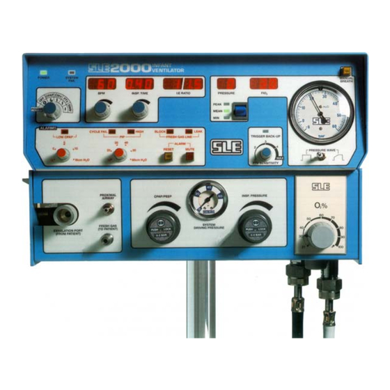
7. Ventilator Description The SLE 2000 consists of two linked modules, Electronic and Pneumatic. Electronic Module Pneumatic Module 7.1 Front Panel Page 16 of 66... -
Page 17: Function Of Front Panel Controls And Indicators
7.2 Function of Front Panel Controls and Indicators Nº Item Description POWER and Selects Power OFF, ALARM TEST/CPAP, CMV, OPERATIONAL PTV, SIMV modes. MODE Switch POWER LED Indicates power is ‘ON’. SYSTEM FAIL LED When this LED lights and the alarm sounds, it indicates failure of the main processor. - Page 18 Nº Item Description PRESSURE WAVE Permits change of leading edge of pressure wave switch from square to taper in 1-125 BPM range only. ALARM MUTE Mutes audible alarms for one minute. Pushbutton and AIR OXYGEN Sets air/oxygen mix between 21 and 100% 0 ±...
-
Page 19: Functional Tests
Connect mains cable to a suitably rated and grounded electrical power source. Connect SLE approved patient circuit with test lung to the ventilator. For further information see page 44 or instructions supplied with patient circuit. 8.1 Pressure Regulators and Gauges Check the CPAP/PEEP regulator, by turning the control from minimum to maximum making sure the large gauge reads between 0 and greater than 15. -
Page 20: Pre-Setting Alarm Limits
8.2 Pre-setting alarm limits Set the CPAP alarm control to -5 cmH O and the PIP alarm control to 60 cmH 8.3 Power On Automatic Test Set ventilator mode switch to CPAP. The ventilator will now carry out a self test as follows. Power LED shows green and an automatic test of functions &... -
Page 21: Cmv Mode
8.5 CMV Mode Set the following ventilator conditions :- CPAP/PEEP regulator to 10 cmH Re-set Inspiratory regulator to 30 Set the Pressure display switch to PEAK Set PIP alarm control to 40 cm H Advance the mode switch to CMV ... -
Page 22: Simv Mode
Apply slight pressure to test lung and release to simulate patient inspiratory effort. Ensure that with each operation :- • The ventilator cycles once. • The TRIGGER BACK-UP LED is “OFF”. Note: It may be necessary to adjust the PTV sensitivity to achieve correct operation. -
Page 23: Alarm Test
8.8 Alarm Test 8.8.1 Low CPAP Set the following ventilator conditions :- Return the mode switch to CPAP. Set the CPAP/PEEP regulator to 5 cmH • Increase the Low CPAP alarm control to 10 cmH O. The Low CPAP alarm will sound and the LED in the alarm panel will illumuniate. -
Page 24: Leak And Block Alarms
• Increase the PIP alarm control to 40 cmH O. The Cycle Fail visual and audible alarms will be initiated. • Decrease the PIP alarm control to 30 cmH O. The Cycle Fail audible alarm will cancel but the visual alarm will continue. •... -
Page 25: Completing Functional Testing
8.8.5 O Blender Alarm Set Blender to 60%. Disconnect air supply from wall outlet, an audible alarm should be heard from blender. Reconnect air supply, alarm should self cancel. Disconnect supply, an audible alarm should be heard from blender. Reconnect O supply, alarm should self cancel. -
Page 26: Basic Set Up
• To test the system the patient manifold must be occluded or a Test Lung fitted. • Only an SLE approved patient circuit should be used with this equipment Step 2. Set up the humidifier to manufacturer’s instructions Step 3. Set the following ventilator conditions :- Set the mode switch to OFF ... -
Page 27: To Use The Sle2000 In Cpap Mode
Step 5. (a) Set required O concentration by means of O Blender Control. %O Oxygen will be monitored and displayed in Digital Display. The unit should now be ready to connect to a patient. • Changes will take 30 seconds to stabilise on the FlO display. -
Page 28: To Use The Sle2000 In Cmv Mode
8.13 To Use the SLE2000 in CMV Mode As in steps 1 to 5 and CPAP setup. (a) Set INSP.TIME to required rate (displayed in seconds). (b) Select Pressure Wave Shape SQUARE or TAPER. (c) Switch mode switch from CPAP to CMV Note: Ventilator will start to cycle and the alarms will probably sound - press MUTE to silence them. -
Page 29: Patient Triggered Modes
8.14 Patient Triggered Modes 8.14.1 To use SLE 2000 in PTV and SIMV mode As in steps 1 to 5 and CPAP setup (a) Advance the mode switch to CMV (b) Set PTV sensitivity to 1 (c) Set the BPM control to provide either:-... - Page 30 This page is intentionally blank. Page 30 of 66...
- Page 31 Page 31 of 66...
-
Page 32: Ventilator Controls
9. Ventilator Controls 9.1 Electronic module 9.1.1 Power Switch (5 positions) OFF- CPAP- CMV- PTV- SIMV • OFF = All electrical power off. Note: There is a limited fresh gas supply with power switch in the OFF position, if ventilator is used with Headboxes etc. -
Page 33: Ptv Mode
9.1.5 PTV Mode Another main feature of the ventilator is its patient trigger system. This functions without any transducer in the patient circuit, on the principle of monitoring the rate of change of pressure during the onset of inspiratory effort. In fact it measures inspiratory flow by this means and not a pressure plateau. - Page 34 This SIMV feature of the SLE 2000 functions in the following manner: The BPM control setting will determine the number of breaths that will be supplied in each minute. In the period between each of these breaths a time window is opened.
-
Page 35: Inspiration Time
9.1.7 BPM Ten-turn control with LED digital indication to set the breath rate per minute. 9.1.8 Inspiration Time Set by ten-turn control with indication on 3 digit LED display showing the set value in seconds. Invalid settings of the BPM. and INSP.TIME controls are indicated by these two displays flashing. -
Page 36: Three Position Switch
9.1.12 Three position switch. For selecting display of PEAK (maximum), MEAN, or MIN (Minimum) airway pressures. 9.1.13 Pressure Wave Switch This switch alters the pressure waveform from square to tapered as indicated. • This is a Locking Toggle Switch. Pull toggle lever to release. •... -
Page 37: Pneumatic Module
9.2 Pneumatic Module 9.2.1 Proximal Airway Input from patient ET connector to pressure display and internal pressure transducers. 9.2.2 Removable Exhalation Block N2190 Can be removed easily for cleaning by lowering side panel. Pressure release valve 9.2.3 Fresh Gas Port The Fresh Gas port supplies 5 LPM of the blended gas via the humidifier to the patient inspiratory port on the ET connector when the ventilator is switched on. -
Page 38: Regulator And Pressure Gauges
9.2.4 Regulator and Pressure Gauges. • These 2 pressure regulator controls have push/pull locking caps. CPAP/PEEP This regulator controls the base pressure in the circuit. INSP. PRESSURE This regulator controls the peak inspiratory pressure (PIP). SYSTEM DRIVING PRESSURE This guage shows the pressure above CPAP/PEEP. 9.2.5 O Blender (% FlO The oxygen blender controls the amount of oxygen available... -
Page 39: Alarms
10. Alarms Warning Audible and Visual warning alarms indicate a potentially harmful condition to the patient . Failure to take corrective action could result in injury or death to the patient. 10.0.1 Microprocessor The microprocessor system failure and other electronic circuitry failures are alarmed as follows. -
Page 40: Fresh Gas Fail Alarm (Block & Leak)
10.0.4 Fresh Gas Fail Alarm (Block & Leak) This fresh gas failure system will detect either a blockage or a leak in the Fresh Gas supply line. To achieve this there is a small restrictor fitted in the Inspiratory Port of the patient circuit, creating a pressure in the alarm circuitry to the Electronics Module. -
Page 41: Low Cpap Alarm
10.0.8 Low CPAP Alarm Should the circuit pressure fall below the LOW CPAP alarm setting then an audible and visual alarm will be activated. The audible alarm will reset automatically on correct pressure being restored but the visual alarm must be reset by pressing the RESET button. -
Page 42: Auxiliary Output
0 - 4 volts corresponding to 0 to 100% Common ground. Pin 3 All other pins must be left unconnected. SLE reserve the right to use these pins for other uses. • Only SLE approved equipment may be connected to this auxiliary output socket. -
Page 43: Rear Panel
12. Rear Panel 232 SELSDON ROAD SOUTH CROYDON SURREY CR2 6PL U.K. Auxiliary Output Connector TYPE Nº SERIAL Nº SUPPY V ~ Hz POWER A CLASS TYPE Range switch 100% Adjustment FuseHolders Alarm Sounder 100% Adjustment Tool Running Time indicator Gas Inlet Ports CAUTION- ELECTRIC SHOCK HAZARD. -
Page 44: Patient Circuit Connection
SLE3000, Fisher and Paykel or equivalent. DIRECTIONS FOR USE CAUTIONS It is recommended that a high quality bacteria filter (SLE part Make sure that all connections are made properly and are No. N2029) is fitted at the fresh gas connection to the tight before use. - Page 45 REUSABLE 10mm HEATED PATIENT CIRCUIT (SLE Part Nº N2391) This circuit must be clean and sterilised before use. It is designed to be used with an SLE 2000 or SLE2000HFO Infant Ventilator in combination with a Servo controlled humidifier - typically a Fisher and Paykel or equivalent..
-
Page 46: Filter Systems
12 months. For other makes of bacterial filter please refer to manufacturers instructions. 14.2 Bacterial filter, SLE Part Nº:N2587 (Single use) This single use bacterial filter is fitted onto the exhalation block outlet. This filter should be disposed of in accordance with local hospital authority guidelines. A new filter should be used for every new patient. -
Page 47: Cleaning, Disinfection And Sterilization
DO NOT steam autoclave the SLE 2000 or otherwise subject it to temperatures above 62°C. DO NOT immerse any part of the SLE 2000 in any liquid, with the exception of the expiratory exhalation block (SLE part No N2190). 15.1 Preparation of a new ventilator Remove all transit packaging. -
Page 48: Cleaning, Disinfection & Sterilization Chart
• Lift up lever (A) on side of ventilator and lower side flap. • Remove the silencer (B) by pulling it through the hole at the rear. • Remove the exhalation block (C) by firstly taking hold of the block and then pulling it out towards you without the need for undue force. -
Page 49: Disinfection Method
15.5 Sterilization method The silencer SLE part Nº N2186 and exhalation block SLE part Nº N2190 must be sterilized between use on patients. The ventilator cannot be sterilized. The exhalation block must be cleaned as an essential prerequisite to sterilization. -
Page 50: User Operational Checks
16. User Operational Checks 1. Functional test as described on page 19 should be carried out every time the patient circuit is changed. 2. Check the running time meter on the rear of the ventilator to see if preventative maintenance or overhaul is due. Arrange if necessary. 3. -
Page 51: Sle2000 Trouble Shooting Chart
O first. If this gases connected. does not work, disconnect and then connect the Air first. Consult SLE trained Engineer if alarm persists. Repair gas supply Either Air or O gas has failed Check that the difference in... - Page 52 Check sent vent pressure. Proximal Airway line Reconnect tubing. disconnected. Proximal Airway blocked with Clear blockage. water. Solenoid failure. Consult Service Manual or SLE trained Engineer. System Fail - Component failure As above. audible & visual. CPAP Faulty patient circuit. Replace circuit.
- Page 53 Regulator cap is in LOCKED Pull regulator cap out to release position. from locked status. Seized regulator control. Consult SLE trained Engineer. Insp. nozzle blocked. Consult SLE trained Engineer. High alarm condition. Reset alarm setting. Water in proximal airway...
-
Page 54: Service Programmes
18. Service Programmes Service or calibration of this ventilator should only be carried out by an SLE trained hospital engineer or an SLE service engineer. To assist in checking operational use and service periods, the ventilator is fitted with a time elapsed meter. - Page 55 SLE on this product. Contact your distributor for further information. • SLE can offer an exchange service for the complete pneumatic module. Page 55 of 66...
-
Page 56: Pressure Unit Conversion Constants
19. Pressure unit conversion constants k Pascal mmHg 1.000 6.8947 70.308 51.715 6.8947 x 10 k Pascal 0.14504 1.000 10.1973 7.5006 10.000 x 10 14.5 1.000 1019.73 750.06 1.42237 x 0.09806 1.000 0.7355 9.806 x 10 mmHg 1.9337 x 0.13332 1.3595 1.000 1.3332 x 10... -
Page 57: Technical Specification
20. Technical Specification 20.1 Conventional Ventilation Modes: CPAP,CMV,PTV,SIMV BPM Ranges: 1-125 or 126 - 250 breaths per minute (1BPM STEPS) selected via rear security key switch Inspiratory Time: 0.1-3.0 or 0.01-0.3 seconds I:E Range : 9.9:1 - 1:99 calculated from BPM and INSP. TIME settings. -
Page 58: Controls
Alarm Mute and Reset Mute active for 60 seconds (approx.) Pushbuttons: Trigger Sensitivity Control: Range: 2ml/0.5 sec max. To 10ml/0.5sec min. Using SLE N2188 patient circuit. Pressure alarm setting controls: LOW CPAP: -5 to 15cmH PIP :10 to 60 cmH Pressure controls:... -
Page 59: Alarms
20.4 Alarms Audible only: Loss of mains supply: Battery powered alarm Loss of Air or O supply: Blender alarm. Audible and Visual: HIGH CIRCUIT PRESSURE CYCLE FAIL LOW CIRCUIT PRESSURE FRESH GAS BLOCK FRESH GAS LEAK or TOTAL GAS SUPPLY FAIL SYSTEM FAIL: FAIL. -
Page 60: Power , Dimensions Etc
20.6 Power , Dimensions etc. Voltage : 100-120V/ 50-60 Hz 220-250V/ 50-60 Hz Power : 120 VA Fuses : 220-250V~50-60 Hz : Fuse T 1.0A 100-120V~50-60 Hz : Fuse T 2.0A Operating Environment: Temp: 10-40°C Humidity: 0-90% (non condensing) Size, Ventilator only : 37 cms W ×... -
Page 61: Consumables And Accessories For Sle 2000
21. Consumables and Accessories for SLE 2000 MR700 Heater Base usable with all appropriate items listed below N3700/01 (230V) N3700/02 (100V) N3700/03 (115V) N3220 -MR220 Single use chamber (Box of 50) for use with above N2188 - Standard Single use Patient Circuits for use with... - Page 62 N2190 Spare exhalation Block N2029 Bacteria filter (autoclavable) N2587 Bacteria filter (single use) Inlet :22mm (male) Outlet 22mm (female) N2187 Bacteria filter (single use) Inlet & Outlet:15mm (female) or 22mm (male) Tapered Connections N2186 Silencer (fitted to rear of exhalation block) N2035 O (complete) 4 metres length N2199 Air hose, 4 bar (complete) 4 metres length...
-
Page 63: Ordering Information
Reusable circuit start-up kit (Part No. N2200). Option 3 ref. Z0003 Auxiliary 0-15 LPM Blended Output. **State operation required Air Compressors AD 3600, ref. L0035 Suitable for 1 Ventilator AD 2000, ref. L0030 Suitable for 2 Ventilators Page 63 of 66... -
Page 64: Technical Bulletins
Ventilator firmware revision list TB 040301: CPU Boards for serial Nº: E0108 & Y0963 to Y0975 TB 040401: V0226 potentiometer design change Any of the above technical bulletins can be obtained by contacting the SLE Service Department. Page 64 of 66... - Page 65 SLE reserves the right to make changes without prior notice in equipment, publications and prices as may be deemed necessary or desirable. Page 65 of 66...
- Page 66 0120...
Need help?
Do you have a question about the 2000 and is the answer not in the manual?
Questions and answers