Table of Contents
Advertisement
Advertisement
Table of Contents

Related Manuals for SLE SLE1000


Summary of Contents for SLE SLE1000
- Page 1 SLE1000 User manual Version 2.6.4 software...
- Page 2 All rights reserved. No part of this publication may be reproduced, stored in any retrieval system, or transmitted in any form or by any means, electronic, mechanical, photocopy, recording or otherwise, without prior permission of SLE. © Copyright SLE 10/08/2016. Manual : UM114 Issue 21 SLE Part Nº:...
- Page 3 How To Use The SLE1000 CPAP Therapy System The warnings on pages 19 to 22 must be read and understood before using the SLE1000 CPAP Therapy System. Failure to do so could lead to injury of the patient. SETUP THE SLE1000: Page 70 MAKE SURE THAT THE SLE1000’s BACK-UP POWER...
- Page 4 This page is intentionally blank. Page 4 of 128...
-
Page 5: Table Of Contents
1.1. Device ......................10 1.2. Accessories and generic combination devices..........11 1.3. Intended use....................11 1.4. Intended users....................11 2. SLE1000 Description ....................14 3. Description of symbols ..................16 4. User/owner responsibility ..................18 5. Warnings ........................19 5.1. Operational warnings ..................19 5.2. - Page 6 17.2. Operation ......................88 18. Troubleshooting chart ..................90 Technical Information 93 19. Cleaning and disinfection ..................94 19.1. Preparation of a new SLE1000 CPAP driver ..........94 19.2. Cleaning and disinfection of an in-service driver ..........94 19.3. Cleaning Method...................95 19.4. Disinfection method ..................95 20.
- Page 7 23. EMC compliance ....................112 23.1. Electromagnetic immunity ................113 23.2. Recommended separation distances between portable and mobile RF communications equipment and the SLE1000 ............115 24. RS232 ........................116 24.1. RS232 output specification:................116 25. Pneumatic unit schematic SLE1000 ..............117 26.
- Page 8 This page is intentionally blank. Page 8 of 128...
- Page 9 Introduction Page 9 of 128...
-
Page 10: Introduction
2 to 7 bar. The SLE1000 has been designed so that it can be used with only a compressed air supply. The SLE1000 automatically corrects the flow rate, to maintain the set CPAP or maintains the set flow. -
Page 11: Accessories And Generic Combination Devices
1.2 Accessories and generic combination devices The SLE1000 can be used to drive CPAP through a generic humidified and heated patient circuit, with or without a bacteria filter, to any universal patient interface, including nasal prongs, flow generator, or nasal mask that operate within tolerance of chart 1. - Page 12 This page is intentionally blank. Page 12 of 128...
- Page 13 SLE1000 Description Page 13 of 128...
-
Page 14: Sle1000 Description
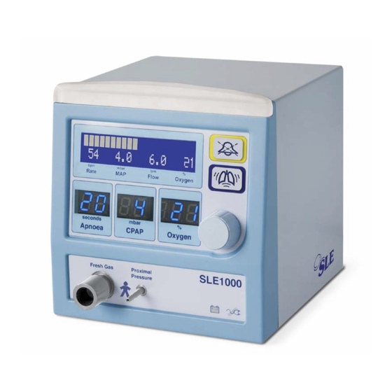
2. SLE1000 Description Main LCD display Light bar Alarm mute button CPAP Boost button Main control knob Set apnoea time display % Oxygen Set pressure display display Fresh gas port Proximal airway port Battery icon Mains disconnect icon Front View... - Page 15 Battery Fuse Holder Mains Fuse Holder Equipotential stud Water trap Oxygen cell cover Mains power switch Exhaust port Oxygen supply Air supply Mains power inlet inlet inlet RS232 Connector Rear View Page 15 of 128...
-
Page 16: Description Of Symbols
3. Description of symbols Symbol Description Read manual (Situated on rear panel). Date of Manufacture (Appears on serial number label). Do not dispose of as general waste (WEEE directive). (Appears on serial number label). EEC conformity marking showing compliance with the Medical Devices Directive. - Page 17 Operational and Clinical Warnings Page 17 of 128...
-
Page 18: User/Owner Responsibility
4. User/owner responsibility The SLE1000 and the authorised accessories for it are designed to be used in accordance with supplied manuals and instructions. This equipment must be periodically checked, recalibrated, maintained (as per maintenance schedule) and components repaired and replaced when necessary for the equipment to operate safely and reliably. -
Page 19: Warnings
Do not use in the presence of flammable anaesthetics. Check the condition of the gas supply hoses to the SLE1000. Do not use any hose that shows signs of cracking, abrasion, kinking, splits, excessive wear or ageing. Make sure that the Air or O hose has not come into contact with oil or grease. - Page 20 13. An alternative form of ventilation should be available whenever the SLE1000 is in use, in the event of failure. 14. Do not touch the patient and SLE1000 metalwork at the same time to avoid earthing the patient. 15. The SLE1000 is not compatible with MRI equipment or other equipment radiating high EM fields.
- Page 21 Allowing the batteries to remain in the deep discharged state will shorten the life of the batteries and the amount of time the SLE1000 can remain on battery power. 30. If the SLE1000 is not to be used for a period in excess of 10 days then disconnect the batteries from the power supply.
-
Page 22: Clinical Warnings
5.2 Clinical warnings Failure to take corrective action when the alarms are activated could result in injury to the patient. There are risks inherent in the use of ventilatory support in the neonatal and infant patient. These may include: Damage to nares. Under- or over- ventilatory support (with consequent abnormalities in blood gases);... - Page 23 User interface Page 23 of 128...
-
Page 24: User Interface
6. User interface The SLE1000 user interface comprises of one LCD display (1), three LED displays (2), one push and turn knob (3), two push buttons (4) and light bar (5). The SLE1000 is controlled solely through items 3 and 4. -
Page 25: Push And Turn Knob
6.3 Push and turn knob (3) The push and turn knob is the sole method of selection and adjustment of driver parameters. 6.3.1 Operation To select a parameter rotate the knob in either direction (clockwise or anti clockwise). Once the user has started to rotate the % Oxygen parameter will start to flash, continue to rotate the knob and the user will cycle through the adjustable parameters or selectable displays (dependent on mode the user has selected). -
Page 26: Operation
7. Operation 7.1 Power up 1. Push the power button on the rear of the machine for 3 seconds. Note: If the battery indicator and mains indicator lights on the front panel are both illuminated, the unit cannot be turned on. See “Battery and mains indicators”... - Page 27 5. At 2 in the Apnoea display window the light bar and audio paused button should become illuminated with yellow LEDS. 6. At 1 in the Apnoea display window the light bar only should become illuminated with blue LEDS 7. At 0 in the Apnoea display window the light bar should switch off.
- Page 28 9. The unit will then enter Standby mode. 10.The unit will now calibrate the oxygen monitoring system, starting with the 21% point. This is indicated by “CAL” being displayed in the lower right of the LCD. 11.The unit will now calibrate the oxygen monitoring system, starting with the 100% point.
-
Page 29: Oxygen Calibration Routine Description
"O2 Calib Error" is displayed. 7.2 Oxygen calibration routine description The SLE1000 oxygen calibration routine is as follows: The first 180 seconds after power up the unit calibrates the system using air. The unit displays the text “CAL” in upper case characters. -
Page 30: Power Down
40. This check is not limited to the first four hours of operation. The unit automatically recalibrates the oxygen every 8 hours unless a calibration error has occurred, (i.e. using the SLE1000 with air only) then the unit calibrates every hour. -
Page 31: Standby Mode
8. Standby mode On power up the unit enters “Standby” mode. In “Standby” mode the unit reduces the flow to less than 2 l/min. Stand-by mode is indicated in the CPAP LED display by one horizontal dash “-”. The LCD displays “Standby...”. -
Page 32: Selecting A Parameter, Display Or Calibration Function
9. Selecting a parameter, display or calibration function 9.1 Upper and lower level functions. The following is a the list of selectable parameters using the control knob: Set Oxygen Level Parameter - lower level function Set CPAP level Parameter - lower level function Set Apnoea Time Parameter - lower level function Set Trigger Sen. - Page 33 Rotate the knob to the left to cycle through the selectable parameters, displays or calibration functions. The screen will display the title of the parameter that can be adjusted. Push the knob to adjust the flashing parameter. The LCD display changes from “Set Apnoea time”...
- Page 34 Push the knob to confirm the setting. The LCD display will return to displaying “Flow Mode”. Note: If the unit is delivering CPAP then the Cycle indicator bargraph is displayed. See section 12.1 on page 51. Note: Failure to push the knob to confirm the setting will cause the set value to be discarded...
- Page 35 9.1.2 Selecting upper level functions Note: For the user to select an upper level function the unit will have to be in either "Flow Mode" or "CPAP" mode. The procedure is the same for all the settable functions or displays.. The display messages are located in the LCD window.
- Page 36 Push the knob to select. Page 36 of 128...
-
Page 37: Upper Level Functions, Displays And Parameters
9.2 Upper level functions, displays and parameters 9.2.1 Pressure trigger sensitivity Push or turn the knob. Rotate the knob until the text “Set Trigger Sen.” appears and starts to flash. Push the knob to select. The default value of 3 is displayed. - Page 38 Rotate the knob to increase or decrease the valve. The trigger sensitivity has a range of 1 to 6, with the default being 3. 1 being least sensitive. 6 being most sensitive. Push the knob to select the new sensitivity setting. The unit display returns to the Flow mode.
-
Page 39: Showing Battery Charge Level
9.3 Showing battery charge level Rotate the knob to select the “Show Batt. level” and starts to flash. Push the knob and the battery charge level will be displayed. Push the knob to return to the default display. Note: The battery level times out after 8 seconds. - Page 40 9.3.1 100 % O Calibration Push or turn the knob. Rotate the knob until the text “Start O2 Calib” appears and starts to flash. Push the knob to select. Page 40 of 128...
- Page 41 Rotate the knob to select the 100% Oxygen calibration routine. Push the knob to start the 100% Oxygen calibration routine. The unit display returns to the Fixed Flow mode but displays the word “cal” in the measured percentage of Oxygen area. (See “Oxygen calibration routine description”...
-
Page 42: Alarm History
9.4 Alarm history Push or turn the knob. Rotate the knob until the text “Show Alarm Hist.” appears and starts to flash. Push the knob to select. The most recent alarm to be generated will be displayed. This is indicated by -1. - Page 43 Rotate the knob to scroll through the last 25 alarm messages. Push the knob to return to the default display. Note: The alarm history times out after 6 seconds. Note: The alarm history is cleared when the unit is turned off. Page 43 of 128...
-
Page 44: Set Flow
9.5 Set Flow Push or turn the knob. Rotate the knob until the text “Set Flow.” appears and starts to flash. Push the knob to select. The default flow value of 6 l/min will be displayed in the right hand corner. Note: If a Flow value has already been set during the session the unit will... - Page 45 Rotate the knob to select the required flow. As the flow value is changed the text will flash. Confirm the setting. The unit will enter flow mode. Note: Please see the “CPAP and Flow mode” chapter for a detailed description on page 55. Page 45 of 128...
-
Page 46: Elapsed Time Counter
9.6 Elapsed time counter The SLE1000 has an hour counter which records the total elapsed in use time. To access the display, press the “Audio paused” and “Boost” buttons together. The text “Been used for: N h” will be displayed. -
Page 47: Audio Mute Button
10. Audio mute button 10.1 Pre-mute The user has the ability to pre-mute the alarm system. The user pushes the audio paused button once. The unit will alternate between the text “Audio Paused” and the cycle indicator bargraph. The unit will flash the light bar (Blue) when the text “Audio Paused”... -
Page 48: Audio Paused
10.2 Audio paused The user has the ability to mute the alarm system. When an alarm has been triggered, the user pushes the audio paused button once. The unit will display the text “Audio Paused”. Note: The alarm message will alternate between the alarm message text and the audio paused text. - Page 49 If the alarm condition has been cleared the SLE1000 returns to CPAP mode. Note: The audio mute button has a third function of setting alarm thresholds in flow mode. See page 67.
-
Page 50: Boost Button
11. Boost button The boost button delivers an up to 3 mbar above the measured flow. The boost is maintained whilst the button is pressed, up to 30 seconds. The boost is delivered at the set Oxygen percentage. In the main display the text +3 is displayed. -
Page 51: Indicators
12. Indicators 12.1 Cycle indicator bargraph When the SLE1000 is delivering CPAP the LCD displays a airway pressure bargraph. The bargraph is an indication of breath cycling (mechanical or patient). The bargraph has a span of ±2.5 mbar around the measured mean airway pressure. -
Page 52: Averaged Value
12.3 Averaged value 12.3.1 BPM The BPM is an averaged value from a 30 second rolling window. 12.4 Measured values 12.4.1 MAP The Mean Airway Pressure (MAP) is a measured value in mbar. 12.4.2 Flow The Flow is a measured value in l/min. -
Page 53: Battery And Mains Indicators
8 hours. It is not recommended that the unit be used on battery power when mains power is available. The purpose of SLE1000 battery is to allow continued operation in the event of a mains power failure. - Page 54 This page is intentionally blank. Page 54 of 128...
- Page 55 CPAP & Flow mode Page 55 of 128...
-
Page 56: Cpap & Flow Mode
13. CPAP & Flow mode This chapter describes in detail the procedure of selecting either CPAP or Flow mode. 13.1 Standby to Flow mode Push the knob. The Oxygen parameter will start to flash. Rotate the knob to the left to the CPAP parameter. - Page 57 Rotate the knob to the right to set the control to the “--” Push the knob to confirm the setting. The unit will enter "Flow Mode" mode (set at 6 l/min). Note: If a Flow value has already been set during the session the unit will use this value.
-
Page 58: Setting A Flow In Flow Mode
13.2 Setting a flow in flow mode Push the knob. Note: The default value of 6 l/min is used. The Oxygen parameter will start to flash. Rotate the knob to the right to select "Set Flow". Page 58 of 128... - Page 59 Push the knob to select. The flow will now be displayed in the top right hand corner of the display Rotate the knob to the right to set the required flow. The text will starts to flash. Push the knob to confirm the required flow.
- Page 60 The SLE1000 will start to deliver the set flow. At this stage the light bar will illuminate with a medium priority colour. This is to inform users that the alarm thresholds require setting. Note: The user should be aware that in “Flow Mode” the trigger thresholds for the “High leak”...
-
Page 61: Flow Mode To Cpap Mode
13.3 Flow mode to CPAP mode The user is in “Flow Mode”. Push or turn the knob. Rotate the knob to the left to select the “Set CPAP level”. Page 61 of 128... - Page 62 “Adjust Parameter”. Rotate the knob to the right to adjust CPAP parameter. Push the knob to confirm the setting. The SLE1000 will now adjust the pressure. The message display now changes to the airway pressure bargraph. Page 62 of 128...
-
Page 63: Standby To Cpap Mode
13.4 Standby to CPAP mode Push or turn the knob. The Oxygen parameter will start to flash. Rotate the knob to the left to the CPAP parameter. Push the knob to select the parameter. Page 63 of 128... - Page 64 CPAP. The text adjust parameter will be displayed. Push the knob to confirm the setting. The SLE1000 will now adjust the pressure. The message display now changes to the airway pressure bargraph. Page 64 of 128...
-
Page 65: Cpap To Flow Mode
13.5 CPAP to Flow mode The user is in CPAP mode. Push the knob. Rotate the knob to the right to select "Set Flow". Page 65 of 128... - Page 66 Push the knob to select. The flow will now be displayed in the top right hand corner of the display Rotate the knob to the right to set the required flow. The text will starts to flash. Push the knob to confirm the required flow.
- Page 67 The SLE1000 will now deliver the set flow. At this stage the light bar will illuminate with a medium priority colour. This is to inform users that the alarm thresholds require setting. Note: The user should be aware that in “Flow Mode” the trigger thresholds for the “High leak”...
- Page 68 This page is intentionally blank. Page 68 of 128...
- Page 69 SLE1000 Set-up Page 69 of 128...
-
Page 70: Sle1000 Set-Up
14. SLE1000 Set-up 14.1 First use Setting up the SLE1000 for the first time. Step 1. Take the SLE1000 out of its transport carton and remove the protective film. Step 2. Remove the air and oxygen inlet port caps. Step 3. - Page 71 Step 4. The SLE1000 is shipped with the main battery disconnected. Using a screw driver remove the battery fuse holder. (Indicated by arrow) Step 5. Insert the fuse into the fuse holder. (T2.0A 250V). (The fuse is located in the accessory pack, Part nº: M0457/...
-
Page 72: Rotation Of Gas Inlets
14.3 Water trap and particulate filter Each SLE1000 unit is fitted with a water trap and particulate filter in the air side of the pneumatic system. The water trap is auto-draining. The particulate filter will remove particles of more than 5 micrometer (Microns) in size. -
Page 73: Standard Setup
14.4 Standard setup SLE1000 can be used with air and oxygen gas supplies or air only. For use with air and oxygen start with section 14.4.1 on page 73 and for air only start with section 14.4.2 on page 74. - Page 74 Connect the air hose to the SLE1000. Step 5. Connect the air hose to the wall supply. Step 6. Connect SLE1000 to mains power. Do not turn the SLE1000 on. Proceed to “Functional testing prior to patient use” on page 80...
- Page 75 Block the outlet momentarily to allow the mechanism to close. Step 10. Connect SLE1000 to mains power. Do not turn the SLE1000 on. Proceed to “Functional testing prior to patient use”...
-
Page 76: Disconnection Of Air And Oxygen Hoses
14.5 Disconnection of air and oxygen hoses Warning: The SLE1000 does not produce any pneumatic noise when turned off. Always disconnect the air and oxygen hoses from the wall outlets prior to disconnection from the unit. Step 1. Disconnect the air and oxygen hoses to the wall supplies. -
Page 77: Battery Charging
14.6 Battery charging 14.6.1 Prior to first use The SLE1000 should be connected to mains power for 8 hours prior to first use to allow the batteries to charge. After 8 hours confirm that the battery status indicator reads 100%. -
Page 78: Mains Isolation
14.9 Mains isolation To isolate the SLE1000 electrically from the mains supply, remove the mains plug. 14.10 Extended storage and transportation 14.10.1 Storage If the user is intending to store the driver for a period greater than 10 days and is unable to charge the batteries during this time as recommended in the “Warnings”... - Page 79 Functional Testing Page 79 of 128...
-
Page 80: Functional Testing Prior To Patient Use
89, then the unit should not be used until it has been repaired. Please contact an SLE approved engineer, or SLE. 1. Connect the delivery circuit and flow generator as per the manufacturer’s instructions. -
Page 81: Battery Test
15.1 Battery test. 1. Disconnect the mains plug. 2. Turn on the SLE1000. Caution: If both the battery indicator and mains icon flash when the power button is depressed the battery is depleted. Connect mains power and allow the unit to charge for a minimum of 8 hours. The user can use the unit, but... -
Page 82: Total Power Fail Alarm Test
Press the alarm button twice to clear the alarm message. 21. Remove the occlusion from the generator outlet. 22. The SLE1000 should display and sound the “HIGH LEAK” alarm after approximately 1 minute. 23. Occlude the generator outlet and the exhaust tube. -
Page 83: Zero Pressure Alarm And Purge Check
15.6 Zero pressure alarm and purge check 34. Disconnect the proximal airway tube from the proximal pressure port. 35. The SLE1000 should display and sound the “Zero Pressure” alarm. 36. Occlude the Proximal Pressure port. 37. The SLE1000 should display and sound the “High Pressure” alarm. - Page 84 15.7.3 Procedure when using an air compressor 1. Select a CPAP pressure of 12 mbar. 2. Turn off the compressor. The SLE1000 should display and sound the “NO AIR SUPPLY” alarm. Note: The user may have to wait for the pressure in the compressor reservoir to drop, before the alarm is generated.
- Page 85 Operational Considerations Page 85 of 128...
-
Page 86: Operational Considerations
16.2 CPAP 16.2.1 CPAP setting of 2 to 4 mbar If the user is using the SLE1000 with small or medium prongs and a CPAP pressure of between 2 and 4 mbar, the unit may not detect the disconnection of the patient from the circuit. - Page 87 Operation Page 87 of 128...
-
Page 88: Basic Operation
Step 1 Setup the SLE1000 as described in section 14.4 on page 73. Step 2 Ensure that the SLE1000 has been functionally tested as described in section 15. on page 80. Step 3 Ensure the unit has calibrated the oxygen system. - Page 89 Troubleshooting Chart Page 89 of 128...
-
Page 90: Troubleshooting Chart
18. Troubleshooting chart Symptom Possible Cause Remedy Alarm message: Proximal pressure exceeds 15.5mbar. High Pressure Nasal prongs blocked Check patient connection. Filters occluded with water. Check patient circuit. Exhaust tube blocked. Alarm message: Air supply is too low (<2.0 bar) to No Air Supply assure normal operation. - Page 91 Symptom Possible Cause Remedy Alarm message: Unit started with complete circuit Disconnect proximal airway Gas Flow Error attached. line and cycle power. Alarm message: Water in circuit creating circuit noise. Check patient circuit. High BPM rate Adjust trigger sensitivity. See “High BPM rate” on page 100. Page 91 of 128...
- Page 92 This page is intentionally blank. Page 92 of 128...
-
Page 93: Technical Information
Technical Information Page 93 of 128... -
Page 94: Cleaning And Disinfection
DO NOT steam autoclave the driver or otherwise subject it to temperatures above 62°C. DO NOT immerse any part of the driver in any liquid 19.1 Preparation of a new SLE1000 CPAP driver Remove all transit packaging. Inspect the fresh gas port and proximal airway port for any packing material. -
Page 95: Cleaning Method
19.3 Cleaning Method Note: Cleaning is an essential prerequisite to disinfection and sterilization. For cleaning use three clean, disposable, absorbent, non-shedding cloths. Wipe clean with the first cloth using a hand hot water/mild general purpose detergent solution (as prescribed by the appropriate hospital authority). Do not overload the cloth with liquid. Remove the water/mild general purpose detergent solution with the second cloth using water only. -
Page 96: Messages & Alarms
20. Messages & alarms 20.1 Messages The user interface messages displayed on 20 character wide LCD. User message Description Action Airway pressure Indicates normal (technical and None bar graph (non- patient) operation. Tolerable scaled) underlying conditions have been acknowledged by the user. Audio Paused Indicates that user has activated the Resets any current alarm... - Page 97 Been used for: Display of the battery charge level in The user has to press the percent alarm mute button to cancel display. SLE1000 Ver. N.N Version display during power-on-self- Clears itself on completion test. of the power-on-self-test. Ready... Indicates that power-on-self-test has Clears itself after 2 sec.
-
Page 98: Alarm Messages And Sounds
20.2 Alarm messages and sounds. 20.2.1 Alarm messages. Alarm messages ranked in order of priority. The current message of highest priority ranking is stored in the history log. Simultaneous lower ranking messages are often the consequence of a higher priority, and they are not stored in the history log. The term ‘alarm’, when used in the Action column, means sounding and displaying a conforming audio-visual alarm. - Page 99 Alarm message Description Action Single or multiple sub- System Failure N System Failure system failures. Latching HIGH priority alarm. Remove patient to an N = system failure alternative form of number which can be Cannot be disabled. ventilation. Remove the unit between 1-255.
- Page 100 Alarm message Description Action Device will deliver 100% No Air Supply Air supply is too low (<2.0 bar) to oxygen as set flow. assure normal operation. Connect air supply. If Non-latching HIGH priority alarm. ventilating - remove patient to an alternative form of Suspends high oxygen alarm.
- Page 101 Alarm message Description Action Zero Pressure Measured CPAP is < 0.6 mbar, Fresh gas is set to fixed flow while a flow is being delivered and of 6 l/min, until CPAP >0.9 safety cut out is not in progress. mbar is restored. Indicates a sensor fault or sensor Check Patient, check line disconnect.
- Page 102 Alarm message Description Action High leak alarm triggers when the Check Patient, check High Leak. delivered pressure has dropped by patient circuit. (CPAP mode) 1mbar for set pressures below 5 and 2mbar for set pressures of 5 and more. This condition must be active for at least 10 seconds before the alarm is sounded.
- Page 103 Alarm message Description Action High Oxygen Measured oxygen concentration Perform oxygen cell re- >5% of set FiO calibration. This suspends oxygen (could potentially result from cell monitoring for 4 minutes. calibration value corruption). Non-latching HIGH priority alarm. If alarm repeats, remove patient to an alternative Cannot be disabled.
- Page 104 Alarm message Description Action Connect mains power. Mains Disconnect Mains power is disconnected or has failed, or mains fuse has failed. If mains power cannot be Device continues to operate on restored, cancel alarm and battery power. monitor battery level. Light-up mains disconnect indicator on front panel.
- Page 105 20.2.2 Alarm tone composition and duration The unit produces three alarm tones. The three pulsed tones correspond to the alarm sounder priorities, High, Medium and Low. The pulsed tones are generated when the unit encounters an alarm condition. All the generated tone alarms are accompanied by visual alarm indication.
-
Page 106: Technical Specification
21. Technical specification 21.1 Operating mode Pressure: 2 – 12 mbar (Resolution 1 mbar). Flow: 4 -14 l/min (Resolution 1 l/min) Apnoea time: 5 – 90 sec, OFF (Resolution 5 sec). 21 – 100% (Resolution 1 %). Boost button: CPAP +3 mbar up to 30 sec. 21.2 Monitoring Mean airway pressure: 0 –... -
Page 107: Alarms
21.5 Alarms Alarm mute/pre-mute: 120 sec 21.5.1 User settable Apnoea Range 5 to 90 seconds, OFF (Resolution 5 second steps). 21.5.2 Auto-set alarms Battery fail Mains disconnect System/Comm Fail Calib Faulty High Pressure No Air Supply No Oxygen Supply High BPM rate High Leak Zero Pressure Exhaust Impeded... -
Page 108: Gas Supplies
21.8 Gas supplies The air and oxygen high pressure gas supplies are used as fresh gas. Note: The unit will only operate reliably if the difference in pressure between the Air and Oxygen supply is less than 3 bar. 21.8.1 Oxygen supply The driver requires a supply of pure oxygen between 2 to 7 bar 21.8.2 Air supply The driver requires a supply of medical grade compressed air to... -
Page 109: Power Requirements
500 hPa to 1060 hPa 21.14 Product life cycle The SLE1000 has a product life of 8 years from the date of manufacture. This excludes the main battery which has a 2 year life and the oxygen cell which has a 1 year life. -
Page 110: Maintenance Schedule
36 months preventative maintenance 48 months preventative maintenance Note: Remove the battery fuse if the SLE1000 is stored for longer than 2 weeks, whilst disconnected from the mains. The power button detection circuit consumes a small amount of current, which can cause the battery to discharge over a long period. -
Page 111: Preventative Maintenance
22.3 Preventative Maintenance 22.3.1 12 / 36 months preventative maintenance Perform preventative maintenance. Replace Oxygen cell, Qty 1. Replace inlet filters. 22.3.2 24 /48 months maintenance: Perform preventative maintenance. Replace Oxygen cell, Qty 1. Replace lead-acid battery, Qty 1. Replace inlet filters. Inspection of pneumatic unit and replacement of worn components as per check list. -
Page 112: Emc Compliance
Guidance and manufacturer's declaration - electromagnetic emissions The SLE1000 is intended for use in the electromagnetic environment specified below. The customer or the user of the SLE1000 should assure that it is used in such an environment. Emissions test Compliance... -
Page 113: Electromagnetic Immunity
23.1 Electromagnetic immunity Guidance and manufacturer's declaration - electromagnetic immunity The SLE1000 is intended for use in the electromagnetic environment specified below. The customer or the user of the SLE1000 should assure that it is used in such an environment. - Page 114 Guidance and manufacturer's declaration - electromagnetic immunity The SLE1000 is intended for use in the electromagnetic environment specified below. The customer or the user of the SLE1000 should assure that it is used in such an electromagnetic environment. Immunity test...
-
Page 115: Recommended Separation Distances Between Portable And Mobile Rf Communications Equipment And The Sle1000
RF communications equipment and the SLE1000 The SLE1000 is intended for use in an electromagnetic environment in which radiated RF disturbances are controlled. The customer or the user of the SLE1000 can help prevent electromagnetic interference by maintaining a minimum between portable and mobile RF communications equipment (transmitters) and the SLE1000 as recommended according to the maximum output power of the communications equipment. -
Page 116: Rs232
24. RS232 24.1 RS232 output specification: Baud rate 19.2kbps 8-bit data 1 stop bit No Parity No hardware handshake Continuously outputs current monitored values in an ascii text string that is 36 characters long. Characters (‘x’ denotes an ascii character): 0-15 'xxxxxxxxxxxxxxxx"... -
Page 117: Pneumatic Unit Schematic Sle1000
25. Pneumatic unit schematic SLE1000 Below is a schematic representation of the pneumatic unit of the SLE1000. Page 117 of 128... -
Page 118: Sle1000 Overlay
26. SLE1000 Overlay Labels are supplied as a set of 4 and cannot be ordered individually. Units in cmH O are also available. Please contact SLE or your distributor for more information. Page 118 of 128... -
Page 119: Equipment Checklist
Qty1 M0457/2AC/001 SLE1000 Trolley Fixing Screws Qty1 Qty2 L1009/020/0XX H6212 L1009/010/0UK Accessory pack Note: The air and oxygen hoses are supplied separately. Note: Please contact SLE or your distributor for more information on the start-up pack. Page 119 of 128... - Page 120 This page is intentionally blank. Page 120 of 128...
- Page 121 Consumables & Accessories Page 121 of 128...
-
Page 122: Consumables And Accessories
NIST probe N2199 Oxygen hose (4m long NIST probe N2035 Water trap filter. Replacement SLE1000 roll stand, deluxe (with drip pole, medi L1009/014/000 rail, basket and hose hook. (Medicart 4) SLE1000 roll stand, basic. (Medipole 1000) L1009/015/000 SLE1000 user manual... - Page 123 Glossary Page 123 of 128...
-
Page 124: Glossary Of Abbreviations Used In This Manual
29. Glossary of abbreviations used in this manual Oxygen °C Degrees Celsius ≈ Approximately equal to Unit of Barometric Pressure Breaths Per Minute Centimetre Centimetres of Water CPAP Continuous Positive Airway Pressure Electromagnetic Compatibility Fractional Concentration of Inspired Oxygen Kilogram Liquid Crystal Display Light Emitting Diode l/min... -
Page 125: Index
30. Index Cleaning prior to first use 94 Cleaning when in service 94 Controls 106 Abbreviations, used in the manual 124 CPAP boost 16 Accessories 10 CPAP driver 10 Adjust Parameter 96 CPAP mode 47 Air & oxygen hoses, disconnection 76 Cycle indicator 51 Air supply 108 Alarm history 42... - Page 126 Maintenace schedule 110 Show Batt. Level 32 Maintenance 111 Show Batt. level 97 Measured values, MAP 52 SLE1000, set-up 70 Measured values, oxygen 52 Standard setup 73 Messages 96 Standby mode 86 Monitoring 88, 106 Start O2 Calib 32, 97...
- Page 127 SLE reserves the right to make changes without prior notice in equipment, publications and prices as may be deemed necessary or desirable. Page 127 of 128...
Need help?
Do you have a question about the SLE1000 and is the answer not in the manual?
Questions and answers