Table of Contents
Advertisement
Quick Links
Advertisement
Table of Contents
Troubleshooting

Subscribe to Our Youtube Channel
Related Manuals for SLE SLE2000


Summary of Contents for SLE SLE2000
- Page 1 SLE2000 Service manual...
- Page 2 All rights reserved. No part of this publication may be reproduced, stored in any retrieval system, or transmitted in any form or by any means, electronic, mechanical, photocopy, recording or otherwise, without prior permission of SLE. © Copyright SLE 19/03/2012. Manual : SM7 Issue 12 SLE Part Nº:...
-
Page 3: Table Of Contents
Contents 1. Introduction ....................... 8 2. Principles of operation SLE2000 valveless system ........... 8 3. User/owner responsibility ..................10 4. Warnings ........................11 5. Symbols used on or in the equipment ............... 12 6. Glossary of abbreviations ..................13 7. Ventilator control description ..................16 7.1. - Page 4 13.5. Functional testing (Post soak)...............58 13.5.1. Perform Electrical Safety Test..............58 4.0.1. Basic Operation..................58 4.0.2. Mains Voltage tolerance test..............60 4.1. SLE 2000 Electrical Troubleshooting Chart ............62 4.2. SLE 2000 Pneumatic Troubleshooting Chart..........63 5. Technical Specification ....................66 5.1. Conventional Ventilation .................66 5.2.
- Page 5 7.1.3. SI 990302 Possible inadvertant solenoid failure messages ....160 7.1.4. SI 000201 Leak Alarm Trigger Threshold..........162 7.1.5. SI 020901 Cleaning, Disinfection and Sterilisation of SLE ventilators..164 7.1.6. SI 031101 N2183 0-4 bar pressure gauge ..........165 7.1.7. SI 050301Maximum Mean & Min Pressure Selection Switch....166 7.1.8.
- Page 6 7.2.1. TB 990603 Removal of hour counter from electrical chassis....174 7.2.2. TB 000201 New versions of control software...........175 7.2.3. TB 000801 Ventilator Firmware Status ............176 7.2.4. TB 040301 SLE2000 CPU Boards ............179 7.2.5. TB 040401 V0226 Potentiometer .............181 7.2.6. TB060901 Alarm sounder replacement at 10,000 hr overhaul....182 6.
- Page 7 Introduction (SLE2000) Page 7...
-
Page 8: Introduction
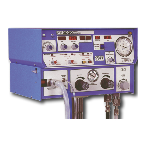
1. Introduction The SLE2000 is a constant flow, time cycle, and pressure limited neonatal ventilator with patient triggering. Main features are that it has no expiratory valve but uses a reverse flow of mixed gas that is injected from the exhaust manifold into the expiratory limb of the patient circuit. This flow of gas has the effect of compressing 5 LPM humidified gas into the patient ET tube. - Page 9 60 BPM * The Valveless Ventilation Principle was designed and patented by Prof. J G Whitwam and Mr. M. K. Chakrabarti of the R.P.G.M.S Hammersmith Hospital. This patent is exclusively licensed to SLE (SLE2000) Page 9...
-
Page 10: User/Owner Responsibility
SLE or parts which are otherwise approved by SLE. Equipment which is not functioning correctly or is otherwise in need of repair or maintenance... -
Page 11: Warnings
Do Not use oil or grease on oxygen fittings or where oxygen is used. The ventilator functional tests must be carried out each time the SLE 2000 is used on patients. If any of these tests do not function as described then there is a problem and the ventilator must not be used until it is rectified. -
Page 12: Symbols Used On Or In The Equipment
3 months, it is recommended that the battery be removed. Two externally accessible fuses are; Mains Fuses Type T 0.2 amps. For 200 - 250V Type T 0.5 amps. For 100 - 120V Page 12 (SLE2000) -
Page 13: Glossary Of Abbreviations
......Pounds per Squire Inch Gauge SIMV ...... Synchronous Intermittent Mandatory Ventilation VAC......Volts, Alternating Current Vt......Tidal Volume Nist......Non interchangable Standard Terminal PTV ......Patient Triggered Ventilation PIP ......Peak Inspiratory Pressure ms ......Millisecond (SLE2000) Page 13... - Page 14 This page is intentionally blank. Page 14 (SLE2000)
- Page 15 Ventilator Control Description (SLE2000) Page 15...
-
Page 16: Ventilator Control Description
7. Ventilator control description The SLE 2000 consists of two linked modules, Electronic and Pneumatic. Electronic Module Pneumatic Module 7.1 Front Panel Page 16 (SLE2000) -
Page 17: Function Of Front Panel Controls And Indicators
Proximal Airway Pressure. This pressure is to +60 cmH displayed more accurately by the independent digital display. PTV SENSITIVITY Variable patient trigger level setting. control Sensitivity between 1(least sensitive to patient effort) and 5 (most sensitive to patient effort). (SLE2000) Page 17... - Page 18 PIP, CYCLE FAIL Sets visual and audible alarm level for inspiratory and HIGH alarm pressure between 0 and 60 cmH LED’s with control CPAP Alarm LED Sets visual and audible alarm level for CPAP and control pressure. Page 18 (SLE2000)
-
Page 19: Rear Panel
7.3 Rear panel Nº Item calibration adjustment. 125 - 250 BPM range switch Aux. Output socket. Fuse Holders Optional serial port Running Time Indicator adjustment tool. Alarm sounder (SLE2000) Page 19... -
Page 20: Side Panel
7.4 Side panel Nº Item Side flap latching mechanism. Fixed jet. Expiratory tube guide. Page 20 (SLE2000) - Page 21 Access to Internal Components (SLE2000) Page 21...
-
Page 22: Accessing The Sle2000 Internal Components
8. Accessing the SLE2000 internal components. Caution: All electrical and pneumatic connections must be disconnected before attempting to gain access to either Electronic or Pneumatic modules. 8.1 ELECTRONIC MODULE 1. Remove 2 screws at rear (A) and 2 screws at each side of the unit (B). -
Page 23: To Remove The A0702/01 Pcb (Runner Mounted)
4. Disconnect the two ribbon cables (C) from the PCB 5. Cut the cable tie connecting the Proximal Airway Tube to PTR1 (D) 6. Pull the Proximal Airway Tube from the transducer. 7. The PCB can now be removed. (SLE2000) Page 23... -
Page 24: To Remove The A0702/01 Pcb (Pillar Mounted)
5. Disconnect the two ribbon cables (C) from the PCB 6. Cut the cable tie connecting the Proximal Airway Tube to PTR1 (D) 7. Pull the Proximal Airway Tube from the transducer. 8. The PCB can now be removed. Page 24 (SLE2000) -
Page 25: To Separate The Two Modules
3. Remove proximal airway pressure tube connection (B). 4. Remove Fresh gas monitoring tube connection (C). 5. Release both locking screws and disconnect the 15 way plug (D). It is now possible to separate the pneumatic module from the electronic chassis. (SLE2000) Page 25... -
Page 26: Removal Of The Oxygen Blender
(D) to be uncoupled. 6. It will now be possible to completely remove blender from module. To install new blender repeat the above process in reverse order. Page 26 (SLE2000) -
Page 27: Removal Of The Oxygen Cell
Firstly gain access to the pneumatic module 8.5.1 Oxygen Cell Mounting The SLE 2000 ventilator has two methods of mounting the Oxygen cell. The first method the oxygen cell is trapped between the manifold and a foam pad, Photograph A. - Page 28 2. Remove the two screws (E) retaining the manifold and lift it clear. 3. Unscrew the old cell. 4. Assembly is the reversal of removal. 5. Screw in the new cell (Part No. N2191) and reconnect the electrical connector. After refitting, recalibrate the cell. Page 28 (SLE2000)
- Page 29 Maintenance (SLE2000) Page 29...
-
Page 30: Maintenance
DO NOT steam autoclave the SLE 2000 or otherwise subject it to temperatures above 62°C. DO NOT immerse any part of the SLE 2000 in any liquid, with the exception of the expiratory exhalation block (SLE part No N2190). -
Page 31: Cleaning, Disinfection & Sterilization Chart
Do not insert any objects into the exhalation block. Rinse the exhalation block in clean water, it must be allowed to dry thoroughly before sterilization. Warning: Ensure that the detergent solution or water does not enter the unit or the exhalation block gas ports on the side of the machine. (SLE2000) Page 31... -
Page 32: Disinfection Method
The exhalation block must be allowed to dry thoroughly before sterilization. 9.1.6 Sterilization method The silencer SLE part Nº N2186 and exhalation block SLE part Nº N2190 must be sterilized between use on patients. The ventilator cannot be sterilized. The exhalation block must be cleaned as an essential prerequisite to sterilization. -
Page 33: Filter Systems
Bacteria Filter N2029 Bacteria Filter The SLE2000 can be used without bacterial filters N2587 in place, but the user must take extra care in not allowing secretions or fluids to enter the ventilators gas ports. -
Page 34: Monthly Operational Checks
Compare digital pressure display with mechanical gauge. Error should not exceed 3%. 9.4.5 Inspiratory nozzle Turn the inspiratory pressure regulator fully clockwise, adjust PIP alarm fully clockwise. Set ventilator to CMV: 60BPM: 0.5 sec inspiration time. Peak inspiration pressure should be greater than 60 cmH Page 34 (SLE2000) -
Page 35: Preventative Maintenance
9.6 Overhaul Overhaul should be carried out at a maximum of 10,000 hours operation or every two years of service which ever is sooner. This overhaul will be performed by an SLE trained hospital engineer or an SLE service engineer. -
Page 36: Service Parts List
N2191 Solenoid Valve SV1-SV3 N2195/05 0-4 Bar regulator N2181 0-2 Bar regulator N2182 ‘O’ Ring N2042 Battery M0484/03 10,000 hour overhaul kits Part number Overhaul kit for NON CE SLE2000 N9000 Overhaul kit for CE SLE2000 N9000/01 Page 36 (SLE2000) - Page 37 Technical Description (SLE2000) Page 37...
-
Page 38: Electronic Module Description
10. Electronic module description The SLE 2000 is arranged in two modules. The Electronic Module is the upper of the two modules which contains all of the electronic controls and displays. 10.1 Description of operation Refer to circuit diagram “Ventilator CPU Board CD/A0702/01 Issue 6” on page 85. The... - Page 39 BZ3 (BZ5 and BZ6 when the A0703/03 board fitted) and also drives the leak alarm LED should the pressure fall below 17.5 cmH O. If the pressure rises above 80 cmH O then the block LED is operated and the audible alarm will activate. (SLE2000) Page 39...
-
Page 40: Pneumatic Module Description
12LPM flow through it required to maintain its accuracy. This bleed is also fed to the oxygen monitoring cell, whose output is connected to the digital F10 display circuitry in the electronics module. Page 40 (SLE2000) - Page 41 The fresh gas transducer PTR2 is mounted in the electronic module and monitors the patient airway pressure. The SLE 2000 because of its unique principle of operation will ventilate the patient without the fresh gas supply. In order to ensure that the patient is always being supplied with fresh humidified gas, a restrictor is fitted in the patient fresh gas tubing close to inspiratory port of the ET connector.
-
Page 42: Fresh Gas System
NV1, which is preset to 5LPM and supplies the fresh gas to the patient circuit via SV2 (high pressure dump solenoid) and a circuit preset pressure relief valve RV2. The SV2 bypass provides a continuous flow of 1LPM through the humidifier in the event of a high pressure dump. Page 42 (SLE2000) -
Page 43: Cpap System
Gas from AIR/OXYGEN Blender is supplied to the CPAP pressure regulator REG2 via the supply manifold. The output pressure of REG2 is fed to the CPAP nozzle in the expiratory manifold, and into the expiratory limb of the patient circuit to create the circuit CPAP pressure. (SLE2000) Page 43... -
Page 44: Inspiratory System
SV1 which controls the breathing rate. If the pressure wave switch is in the taper position then SV3 is energised and the inspiratory flow enters the large volume chamber before reaching the inspiratory nozzle, thus lengthening the pressure rise time. Page 44 (SLE2000) -
Page 45: Pneumatic Circuit Diagram
11.5 Pneumatic Circuit Diagram (SLE2000) Page 45... -
Page 46: Pneumatic Module Parts List
11.6 Pneumatic Module Parts List Page 46 (SLE2000) - Page 47 (SLE2000) Page 47...
- Page 48 This page is intentionally blank. Page 48 (SLE2000)
- Page 49 Setup and Calibration (SLE2000) Page 49...
-
Page 50: Test Equipment Required
12. Test Equipment Required The following test equipment is required to perform the calibration and set up procedures as described in See “SLE2000 Calibration Procedure” on page 51. Electronic: Digital multimeter. Twin beam oscilloscope. Pneumatic: Multi-range Pressure and Flow analyser . -
Page 51: Sle2000 Calibration Procedure
13. SLE2000 Calibration Procedure Note: If electronic module is being set up without the pneumatic module attached, then a dummy load must be connected to 15 way 'D' connector on base of module as a substitute for the solenoid valves. (See “Test Equipment Required” on page 50.) 13.1 Electronic unit preliminary checks and adjustment... -
Page 52: System Watchdog
Then release the collet on the control knob and re-position it so that the pointer points to -5cmH Tighten the collet and rotate the control to point to 15 cmH O and adjust RV9 to give 1.20V 10mV. Repeat adjustment if necessary. Page 52 (SLE2000) -
Page 53: Pip Alarm Threshold Control
This will produce two similar positive going waveforms. Adjust RV200 such that the inter- val between the two leading edges is 200ms 10ms. Time Time Lower Limit Upper Limit Time between the two 190ms 210ms leading edges Confirm that the time is within the limits. (SLE2000) Page 53... -
Page 54: Pneumatic Module Setup And Calibration
4.75 lpm 5.25 lpm Turn off the power to the ventilator and ensure the flow from the fresh gas port is within limits. Flow Flow Lower Limit Upper Limit Fresh gas dump flow 0.70 lpm 1.50 lpm confirmation Page 54 (SLE2000) -
Page 55: Fresh Gas Block And Leak Alarm
Repeat both at 21% and 100% settings until both readings are within 1 percentage point. Check the FiO display accuracy by setting the blender to achieve the following readings on the O analyser and then checking that the FiO digital display on the electronic module is within the limits. (SLE2000) Page 55... -
Page 56: Airway Trigger Calibration (Part 2)
Remove the 2ml syringe and replace with the 10ml syringe. Turn PTV threshold fully anti-clockwise, draw 10ml over 0.5 seconds and ensure that the ventilator triggers on this inspiratory effort. Confirm completion of the Airway Trigger Calibration Page 56 (SLE2000) -
Page 57: Soak Test
O (min) 15cm H O (MAX). Check by setting the pressure switch to min. • Start soak test and record start, time and date. • Run for 50 hours and ensure that there are no component failures. (SLE2000) Page 57... -
Page 58: Functional Testing (Post Soak)
13.5 Functional testing (Post soak). 13.5.1 Perform Electrical Safety Test Equipment under test is: SLE2000 Infant Ventilator Class 1B. The electrical safety test must be carried out on the unit with all the electrical connections intact. Ensure the mains switch on the ventilator is ON for the duration of these tests. - Page 59 Check that the trigger back-up system works properly and that the back-up audible beep and LED are activated when a back-up breath is initialised. Select SIMV Mode • Check operation of the SIMV trigger system, ensuring that back-up audible beep is activated during machine initialised breaths. (SLE2000) Page 59...
-
Page 60: Mains Voltage Tolerance Test
• Reduce the mains voltage by 17% of its nominal value and ensure that normal operation is maintained particularly with regard to the solenoid valves and the displays. Nominal mains voltage Reduce to: 230V 191V 110V 100V Page 60 (SLE2000) -
Page 61: Troubleshooting
TroubleShooting (SLE2000) Page 61... -
Page 62: Sle 2000 Electrical Troubleshooting Chart
4.1 SLE 2000 Electrical Troubleshooting Chart PROBLEM POSSIBLE CAUSE REMEDY 1. When unit is switched ON, a) No A.C power Check wall sockets. POWER light is not illumi- nated, battery fail alarm b) No A.C power to transformer Check: fuses sounds continuously. -
Page 63: Sle 2000 Pneumatic Troubleshooting Chart
4.2 SLE 2000 Pneumatic Troubleshooting Chart Sympton Possible Cause Remedy Blender: Audible Alarm when Air & 1. Air/O differential Ensure Air/O differential supplies are pressure exceeds 20PSI pressure is less than 20PSI connected 2. Jammed Alarm Disconnected Air & O supplies and reconnect. - Page 64 Refer to qualified Service 5. Blocked Inspiratory Engineer nozzle. Refer to qualified Service 6. Faulty PIP regulator Engineer CPAP Desired CPAP pressure As for PIP (see above). cannot be achieved. Excessive residual PEEP Faulty Patient circuit. Replace patient circuit Page 64 (SLE2000)
-
Page 65: Technical Specification
Technical Specification (SLE2000) Page 65... -
Page 66: Technical Specification
HIGH: warning of the PIP alarm limit being exceeded BLOCK: warning of a block in the fresh gas supply limb of patient circuit. LEAK : warning of a leak in the fresh gas supply limb of the patient circuit. Page 66 (SLE2000) -
Page 67: Controls
Alarm Mute and Reset Mute active for 60 seconds (approx.) Pushbuttons: Trigger Sensitivity Control: Range: 2ml/0.5 sec max. To 10ml/0.5sec min. Using SLE N2188 patient circuit. Pressure alarm setting controls: LOW CPAP: -5 to 15cmH PIP :10 to 60 cmH Pressure controls:... -
Page 68: Power , Dimensions Etc
Humidity 15 to 90% (non condensing) for not longer than 2.5 months Atmospheric pressure 500 to 1060hPa for not longer than 2.5 months Protection Class 1 Type B Protection against electric Shock Mode of operation Continuous Page 68 (SLE2000) - Page 69 Circuit Details (SLE2000) Page 69...
-
Page 70: Electronic Circuit Details
6. Electronic Circuit Details 6.1 Display Board A0700/01 Page 70 (SLE2000) -
Page 71: Display Board Circuit Diagram A0700/01
6.1.1 Display Board Circuit Diagram A0700/01 (SLE2000) Page 71... - Page 72 ITEM 5 R0424 330R Resistor 1% 0.25W SMA0207 R408 R0416 150R Resistor 1% 0.25W SMA0207 R407 S0212 IC Socket 16 way DIL SK1 & SK2 S0445 Socket 14 way DIL ITEM 6 M0718 Label, PCB Identification ITEM 7 Page 72 (SLE2000)
-
Page 73: Led Board A0701/01
6.2 LED Board A0701/01 (SLE2000) Page 73... -
Page 74: Led Circuit Board Diagram Cd/A0701/01
6.2.1 LED Circuit Board Diagram CD/A0701/01 Page 74 (SLE2000) - Page 75 Terminal Pin(Pcb single sided) ITEM 5 R0463 10K Resistor 1% 0.25W SMA0207 R403,404 R0416 150R Resistor 1% 0.25W SMA0207 R401, 402, 405 S0242 IC Socket 14 way DIL ITEM 6 (U400) M0718 Label, PCB Identification ITEM 7 (SLE2000) Page 75...
- Page 76 U500 pin 7, Connection of link between C500 and U500 pin 8 and connection of a 68M resistor across pin 5 and 7. (See board drawing AS/A0702/01 issue 5 on page 89 and circuit diagram CD/A0702/01 issue 6 on page 91). Page 76 (SLE2000)
-
Page 77: Ventilator Cpu Board As/A0702/01 Issue 4
6.3 Ventilator CPU Board AS/A0702/01 Issue 4 (SLE2000) Page 77... -
Page 78: Ventilator Cpu Board Cd/A0702/01 Issue 2 Sheet 1 Of 3
6.3.1 Ventilator CPU Board CD/A0702/01 Issue 2 Sheet 1 of 3 A3 version on page 145 of circuit diagram appendix. Page 78 (SLE2000) -
Page 79: Airway Trigger Circuit Diagram Cd/A0702/01 Sheet 2 Of 3
6.3.2 Airway Trigger Circuit Diagram CD/A0702/01 Sheet 2 of 3 (SLE2000) Page 79... -
Page 80: Window Pressure Alarm A0702/01 Sheet 3 Of 3
6.3.3 Window Pressure Alarm A0702/01 Sheet 3 of 3 Page 80 (SLE2000) - Page 81 Crystal 11.0592 MHz 1.00 Each D0571 74HCT138N 1.00 Each D0572 74HCT32N 1.00 Each D0573 74HCT74N 1.00 Each D0574 74HCT573N 1.00 Each D0575 74HCT02N 1.00 Each D0576/01 27C128-20/P 1.00 Each D0577 LM567CN 1.00 Each D0578 74AC540 1.00 Each (SLE2000) Page 81...
- Page 82 R0463 10K Resistor 1% 0.25W SMA0207 10.00 Each R18,19,33,40,42,43,507,50 8,510 & R512 R0467 15K Resistor 1% 0.25W SMA0207 1.00 Each R0469 22.1K Resistor 1% 0.25W SMA020 1.00 Each R204 R0470 23.7K Resistor 1% 0.25W 1.00 Each R500 Page 82 (SLE2000)
- Page 83 M2.5 Plain Nylon Washer 2.00 Each ITEM 32 H3094 M3 S/Proof Washer s.st DIN6798 6.00 Each ITEM 28 H3095 M3 Plain Washer Nylon 6.00 Each ITEM 30 H3093 M3 Plain Washer B . st 2.00 Each ITEM 29 (SLE2000) Page 83...
-
Page 84: Ventilator Cpu Board As/A0702/01 Issue 5
6.4 Ventilator CPU Board AS/A0702/01 Issue 5 Page 84 (SLE2000) -
Page 85: Ventilator Cpu Board Cd/A0702/01 Issue 6
6.4.1 Ventilator CPU Board CD/A0702/01 Issue 6 A3 version on page 147 of circuit diagram appendix. (SLE2000) Page 85... - Page 86 1.00 Each D200 D0570 Crystal 11.0592 MHz 1.00 Each D0571 74HCT138N 1.00 Each D0572 74HCT32N 1.00 Each D0573 74HCT74N 1.00 Each D0574 74HCT573N 1.00 Each D0575 74HCT02N 1.00 Each D0576/01 27C128-20/P 1.00 Each D0577 LM567CN 1.00 Each Page 86 (SLE2000)
- Page 87 1.00 Each R0461 8.2K Resistor 1% 0.25W 1.00 Each R0462 9.09K Resistor 1% 0.25W SMA020 1.00 Each R0463 10K Resistor 1% 0.25W SMA0207 10.00 Each R18,19,33,40,42,43,507,50 8,510 & R512 R0467 15K Resistor 1% 0.25W SMA0207 1.00 Each (SLE2000) Page 87...
- Page 88 M2.5 Plain Nylon Washer 2.00 Each ITEM 32 H3094 M3 S/Proof Washer s.st DIN6798 6.00 Each ITEM 28 H3095 M3 Plain Washer Nylon 6.00 Each ITEM 30 H3093 M3 Plain Washer B . st 2.00 Each ITEM 29 Page 88 (SLE2000)
-
Page 89: Ventilator Cpu Board As/A0702/01 Issue 5
6.5 Ventilator CPU Board AS/A0702/01 Issue 5 See detail A (SLE2000) Page 89... -
Page 90: Ventilator Cpu Board (Detail A)
6.5.1 Ventilator CPU Board (Detail A) Cut track Link R0658 C0481 Page 90 (SLE2000) -
Page 91: Ventilator Cpu Board Cd/A0702/01 Issue 7
6.5.2 Ventilator CPU Board CD/A0702/01 Issue 7 A3 version on page 149 of circuit diagram appendix. (SLE2000) Page 91... - Page 92 1.00 Each D200 D0570 Crystal 11.0592 MHz 1.00 Each D0571 74HCT138N 1.00 Each D0572 74HCT32N 1.00 Each D0573 74HCT74N 1.00 Each D0574 74HCT573N 1.00 Each D0575 74HCT02N 1.00 Each D0576/01 27C128-20/P 1.00 Each D0577 LM567CN 1.00 Each Page 92 (SLE2000)
- Page 93 1.00 Each R0461 8.2K Resistor 1% 0.25W 1.00 Each R0462 9.09K Resistor 1% 0.25W SMA020 1.00 Each R0463 10K Resistor 1% 0.25W SMA0207 10.00 Each R18,19,33,40,42,43,507,50 8,510 & R512 R0467 15K Resistor 1% 0.25W SMA0207 1.00 Each (SLE2000) Page 93...
- Page 94 H2591 M2.5 Nut Full s.st 2.00 Each ITEM 25 H2595 M2.5 Plain Nylon Washer 2.00 Each ITEM 32 H3094 M3 S/Proof Washer s.st DIN6798 6.00 Each ITEM 28 H3095 M3 Plain Washer Nylon 6.00 Each ITEM 30 Page 94 (SLE2000)
- Page 95 Part Number Component Description Qty Used Component Reference(s) H3093 M3 Plain Washer B . st 2.00 Each ITEM 29 W0112 Tinned copper wire 22swg 0.01 Metre See detail A (SLE2000) Page 95...
-
Page 96: Rs232/423 Option
6.6 RS232/423 Option Page 96 (SLE2000) - Page 97 300K 1% 50PPM 0.25W R308 R0557 1K0 Resistor 5% 1W 250PPM PR01 R309,310 C0433 1uF Capacitor 35V 20% Tantalum C300 C0450 0.1uF Capacitor 63V 10% MKS2 C301 S0241 IC Socket 8 way DIL U20,21,22 S0242 IC Socket 14 way DIL (SLE2000) Page 97...
- Page 98 Removal of D0407 Diode and N2096 sounders (See AS/A0703/ 01 Issue 8 on page 107). CD/A0703/01 Issue 6 Removal of D0407 Diode and N2096 sounders. Also see service information “SI 070301 Design and component change to the A0703/01 PSU PCB” on page 173. Page 98 (SLE2000)
-
Page 99: Psu Pcb As/A0703/01 Issue 3
6.7 PSU PCB AS/A0703/01 issue 3 (SLE2000) Page 99... -
Page 100: Power Supply Circuit Diagram Cd/A0703/01 Issue 4
6.7.1 Power Supply Circuit Diagram CD/A0703/01 issue 4 Page 100 (SLE2000) - Page 101 R109,116,121 R0445 2K49 Resistor 1% 0.25W SMA0207 3.00 Each R101,104,105 R0448 3K16 Resistor 1% 0.25W SMA0207 1.00 Each R112 R0449 3.32K Resistor 1% 0.25W SMA 1.00 Each R122 R0457 6K8 Resistor 1% 0.25W SMA0207 1.00 Each R111 (SLE2000) Page 101...
- Page 102 H2094 M2 Shakeproof Washer s.st 6.00 Each ITEM 30 H2093 M2 Plain Washer s.st. 6.00 Each ITEM 40 H3095 M3 Plain Washer Nylon 1.00 Each ITEM 50 W0103 Wire Wrapping Kynar red 30awg 0.01 metre Link Wire Page 102 (SLE2000)
-
Page 103: Psu Pcb As/A0703/01 Issue 7
6.8 PSU PCB AS/A0703/01 issue 7 (SLE2000) Page 103... -
Page 104: Power Supply Circuit Diagram Cd/A0703/01 Issue 5
6.8.1 Power Supply Circuit Diagram CD/A0703/01 issue 5 Page 104 (SLE2000) - Page 105 R103 R0436 1.0K Resistor 1% 0.25W SMA0207 3.00 Each R109,116,121 R0445 2K49 Resistor 1% 0.25W SMA0207 3.00 Each R101,104,105 R0448 3K16 Resistor 1% 0.25W SMA0207 1.00 Each R112 R0449 3.32K Resistor 1% 0.25W SMA 1.00 Each R122 (SLE2000) Page 105...
- Page 106 H2094 M2 Shakeproof Washer s.st 6.00 Each ITEM 30 H2093 M2 Plain Washer s.st. 6.00 Each ITEM 40 H3095 M3 Plain Washer Nylon 1.00 Each ITEM 50 W0103 Wire Wrapping Kynar red 30awg 0.01 metre Link Wire Page 106 (SLE2000)
-
Page 107: Psu Pcb As/A0703/01 Issue 8
6.9 PSU PCB AS/A0703/01 issue 8 (SLE2000) Page 107... -
Page 108: Power Supply Circuit Diagram Cd/A0703/01 Issue 6
6.9.1 Power Supply Circuit Diagram CD/A0703/01 issue 6 Page 108 (SLE2000) - Page 109 R112 R0449 3.32K Resistor 1% 0.25W SMA 1.00 Each R122 R0457 6K8 Resistor 1% 0.25W SMA0207 1.00 Each R111 R0463 10K Resistor 1% 0.25W SMA0207 1.00 Each R114 R0469 22.1K Resistor 1% 0.25W SMA020 1.00 Each R120 (SLE2000) Page 109...
- Page 110 H2094 M2 Shakeproof Washer s.st 6.00 Each ITEM 30 H2093 M2 Plain Washer s.st. 6.00 Each ITEM 40 H3095 M3 Plain Washer Nylon 1.00 Each ITEM 50 W0103 Wire Wrapping Kynar red 30awg 0.01 metre Link Wire Page 110 (SLE2000)
-
Page 111: Back-Up Alarm Sounder As/A0703/03 Issue 1
6.10 Back-up alarm sounder AS/A0703/03 issue 1 (SLE2000) Page 111... -
Page 112: Back-Up Alarm Sounder Circuit Diagram Cd/A0703/03 Issue 1
6.10.1 Back-up alarm sounder circuit diagram CD/A0703/03 issue 1 Page 112 (SLE2000) - Page 113 0.0010 R0473 33K Resistor 1% 0.25W M/Film 70 2.0000 R1 & R2 (See R0279) SMA0207 or VTM491 R0571 10k Resistor 1% 0.125W M/Film 80 2.0000 R3 & R4 R0579 360K Resistor 1% 0.25W M/Film 90 1.0000 SMA0207 (SLE2000) Page 113...
-
Page 114: A0704 P.s.u. Pcb Assembly
6.11 A0704 P.S.U. PCB assembly Page 114 (SLE2000) - Page 115 PARTS LIST Finished Item Stock Number A0704 Finish-d Item Description PSU PCB Assembly Drawing Number AS/A0704 Issue 1 Part Number Component Description Qty Used Component Reference(s) A0703/01 PSU PCB assembly 1.00 A0703/03 Backup sounder PCB assembly 1.00 (SLE2000) Page 115...
- Page 116 Replacemant of N2125 push button switches and O0408 key switch. (See CD/W0288 Issue 3 on page 129) Also see service information letters: “SI 060104 Replacement N2125 push button switches” on page 168 “SI 060301 O0408 key switch replacement” on page 171 Page 116 (SLE2000)
-
Page 117: Cd/W0288 Wireloom Issue 1
6.12 CD/W0288 Wireloom issue 1 A3 version on page 151 of circuit diagram appendix. (SLE2000) Page 117... -
Page 118: Cd/W0288 Wireloom Issue 3
6.13 CD/W0288 Wireloom issue 3 A3 version on page 153 of circuit diagram appendix. Page 118 (SLE2000) - Page 119 “SI 060201 New PCB mounting method” on page 170 “SI 060301 O0408 key switch replacement” on page 171 Introduction of A0704 PSU PCB assembly AS/L0105 Issue 9: Stage 1 build. (See drawing AS/L0105 issue 9 on page 133). (SLE2000) Page 119...
-
Page 120: Electronic Chassis Stage 1 As/L0105 Issue 8
6.14 Electronic Chassis Stage 1 AS/L0105 issue 8 Page 120 (SLE2000) - Page 121 M4 x 20 Pan Hd Pozi s.st 1.0000 Each H4208 M4 x 8 Csk Hd Pozi s.st 2.0000 Each M0219 SLE Name /Data Label 1.0000 Each Drg.DT/M0219 Issue 4 M0266 Fuseholder Shurter Shocksafe 2.0000 Each FIO 0031-1363 Size 20 x...
- Page 122 May 2006 SW2 DELETED CN1138 O0408/01 Keys for O0408 (2 Per) 2.0000 Each Effect Start Stop 31 May 2006 DELETED CN1138 O0408/EAO/01 Keyswitch-EAO Series 51 1.0000 Each Type 51-136.025D2/SLE 18mm dia Effect Start 01 Jun 2006 Stop ADDED CN1138 Page 122 (SLE2000)
- Page 123 1.0000 Each SLE Drg.DT/T0913 Issue T0919 Clamping Disc 15mm 1.0000 Each SLE Drg.DT/T0919 Iss 1 CN0324 T0921 Chassis SLE2000 CE Electronic 1.0000 Each DT/T0921 Iss 6,ART/ T0921 Iss 3" T0923 Brace - EMC SLE2000 2.0000 Each SLE Drg.DT/T0923 Issue T0925 EMC Terminal Cover SLE2000 1.0000 Each...
- Page 124 0.55Mt See drg.SK/0066 W0305 2-Core Oval Cable 2192Y 16/0.2 0.6500 Metre White 0.65Mt See drg SK/ 0065(Cut sleeve used to hold wire during assy) Arrange rear wire flat against panel and front wire horizontally forward as drawn. Page 124 (SLE2000)
-
Page 125: Electronic Chassis Stage 2 As/L0104 Issue 4
6.15 Electronic Chassis Stage 2 AS/L0104 issue 4 (SLE2000) Page 125... -
Page 126: Electronic Chassis As/L0104 Issue 4
6.15.1 Electronic Chassis AS/L0104 issue 4 Page 126 (SLE2000) - Page 127 1 00 Each ITEM 4 A0703/01 PSU Pcb Assembly 1 00 Each ITEM 5 W0288 Wiring Loom SLE2000 El/tronic 1 00 Each ITEM 6 Ensure clearance from inner covers L0104/00 Kit of Assy' Pts 2000 Stg2 EMC 1 00 Each...
- Page 128 M3 x 8 Csk Hd Pozi s st 2 00 Each ITEM 35 H3220 M3 x 20 Csk Hd Pozi s st 2 00 Each ITEM 36 H4125 M4 x 25 Pan Hd Pozi s st 8 00 Each ITEM 38 Page 128 (SLE2000)
-
Page 129: Electronic Chassis Stage 2 As/L0104 Issue 8
6.16 Electronic Chassis Stage 2 AS/L0104 issue 8 (SLE2000) Page 129... -
Page 130: Electronic Chassis As/L0104 Issue 8
6.16.1 Electronic Chassis AS/L0104 issue 8 Page 130 (SLE2000) - Page 131 1 00 Each ITEM 4 A0703/01 PSU Pcb Assembly 1 00 Each ITEM 5 W0288 Wiring Loom SLE2000 El/tronic 1 00 Each ITEM 6 Ensure clearance from inner covers L0104/00 Kit of Assy' Pts 2000 Stg2 EMC 1 00 Each...
- Page 132 M3 x 8 Csk Hd Pozi s st 2 00 Each ITEM 35 H3220 M3 x 20 Csk Hd Pozi s st 2 00 Each ITEM 36 H4091 M4 Nut 2 00 Each H4095/19 Flat Nylon washer 2 00 Each Page 132 (SLE2000)
-
Page 133: Electronic Chassis Stage 1 As/L0105 Issue 9
6.17 Electronic Chassis Stage 1 AS/L0105 issue 9 (SLE2000) Page 133... - Page 134 M4 x 20 Pan Hd Pozi s.st 1.0000 Each H4208 M4 x 8 Csk Hd Pozi s.st 2.0000 Each M0219 SLE Name /Data Label 1.0000 Each Drg.DT/M0219 Issue 4 M0266 Fuseholder Shurter Shocksafe 2.0000 Each FIO 0031-1363 Size 20 x...
- Page 135 2A 250VAC Black Bezel O0408 Keyswitch-Rafi Lumotast 75 1.0000 Each Type 1.15108.912 Round Bezel Effect Start/Stop 31 May 2006 SW2 DELETED CN1138 O0408/01 Keys for O0408 (2 Per) 2.0000 Each Effect Start Stop 31 May 2006 DELETED CN1138 (SLE2000) Page 135...
- Page 136 1.0000 Each SLE Drg.DT/T0913 Issue T0919 Clamping Disc 15mm 1.0000 Each SLE Drg.DT/T0919 Iss 1 CN0324 T0921 Chassis SLE2000 CE Electronic 1.0000 Each DT/T0921 Iss 6,ART/ T0921 Iss 3" T0923 Brace - EMC SLE2000 2.0000 Each SLE Drg.DT/T0923 Issue T0925 EMC Terminal Cover SLE2000 1.0000 Each...
- Page 137 0.55Mt See drg.SK/0066 W0305 2-Core Oval Cable 2192Y 16/0.2 0.6500 Metre White 0.65Mt See drg SK/ 0065(Cut sleeve used to hold wire during assy) Arrange rear wire flat against panel and front wire horizontally forward as drawn. (SLE2000) Page 137...
-
Page 138: Electronic Chassis Stage 2 As/L0104 Issue 9
6.18 Electronic Chassis Stage 2 AS/L0104 issue 9 Page 138 (SLE2000) -
Page 139: Electronic Chassis As/L0104 Issue 9
6.18.1 Electronic Chassis AS/L0104 issue 9 (SLE2000) Page 139... - Page 140 1 00 Each ITEM 4 A0704 PSU Pcb Assembly 1 00 Each ITEM 5 W0288 Wiring Loom SLE2000 El/tronic 1 00 Each ITEM 6 Ensure clearance from inner covers L0104/00 Kit of Assy' Pts 2000 Stg2 EMC 1 00 Each...
- Page 141 M3 x 8 Csk Hd Pozi s st 2 00 Each ITEM 35 H3220 M3 x 20 Csk Hd Pozi s st 2 00 Each ITEM 36 H4125 M4 x 25 Pan Hd Pozi s st 8 00 Each ITEM 38 (SLE2000) Page 141...
- Page 142 This page is intentionally blank. Page 142 (SLE2000)
- Page 143 A3 circuit Diagram Appendix (SLE2000) Page 143...
- Page 144 This page is intentionally blank. Page 144 (SLE2000)
- Page 145 Ventilator CPU board CD/A0702/01 Issue 2 (SLE2000) Page 145...
- Page 146 Page 146...
- Page 147 Ventilator CPU board CD/A0702/01 Issue 6 (SLE2000) Page 147...
- Page 148 Page 148...
- Page 149 Ventilator CPU board CD/A0702/01 Issue 7 (SLE2000) Page 149...
- Page 150 Page 150...
- Page 151 CD/W0288 Wireloom Issue 1 (SLE2000) Page 151...
- Page 152 Page 152...
- Page 153 CD/W0288 Wireloom Issue 3 (SLE2000) Page 153...
- Page 154 Page 154...
- Page 155 Service Information & Technical Bulletins (SLE2000) Page 155...
-
Page 156: Service Information And Technical Bulletins
SI 980302 Ventilator oxygen cells (N2191) SI 990302 Possible inadvertant solenoid failure messages SI 000201 Leak Alarm Trigger Threshold. SI 020901 Cleaning, Disinfection and Sterilisation of SLE ventilators. SI 031101 N2183 0-4 bar pressure gauge. SI 050301Maximum Mean & Min Pressure Selection Switch. -
Page 157: Service Information
+5 volts = valve open. 0 volts = valve closed. The following modifications are required to the SLE 2000 and 2000 HFO Infant Ventilators, if you wish to feed an alarm signal to the INOSYS unit to cut off the supply of NO gas to the patient in the event of a fresh gas supply reduction, due to a high alarm condition or ventilator failure. - Page 158 Pin 3 (0 Volts)screen All other pins must be left unconnected. IMPORTANT: Ventilators and INOSYS units must be checked to verify correct operation after this modification has been carried out. See the appropriate user manuals for these procedures. Page 158 (SLE2000)
-
Page 159: Si 980302 Ventilator Oxygen Cells (N2191)
When fitting replacement cells it is now necessary to remove the old pad from the mounting base first so the new cell with the pad stuck to the bottom can be accomodated. Note: Do not fit an oxygen cell without the foam pad. (SLE2000) Page 159... -
Page 160: Si 990302 Possible Inadvertant Solenoid Failure Messages
Connect a diode (1N4007) in parallel with R34 with its cathode (+ve) connected to the drain of Q4(IRLU110) on all A0702 boards. Additionally, if the ventilator is an SLE2000 then change R32 to 8k2 and R34 to 91k. (0.25W 1% Metal Film) Rationale: The diode will be reverse biassed when Q4 is turned off. - Page 161 Circuit Diagram changes SLE 2000 HFO & HFO ’plus’ Changes SLE 2000 changes (SLE2000) Page 161...
-
Page 162: Si 000201 Leak Alarm Trigger Threshold
This capacitor is being added as standard to all new production and it is recommended that this modification should be carried out during routine servicing. The capacitor used is a 100nf multilayer palladium/ceramic type and can be order from SLE using part Nº: C0481. Alternatively it can be ordered from your local component supply using the Philips part Nº: CW20C 104M... - Page 163 (SLE2000) Page 163...
-
Page 164: Si 020901 Cleaning, Disinfection And Sterilisation Of Sle Ventilators
7.1.5 SI 020901 Cleaning, Disinfection and Sterilisation of SLE ventilators. Subject: Cleaning, Disinfection and Sterilisation of SLE ventilators. Equipment: SLE 2000, SLE2000 HFO, SLE2000 HFO Plus Serial Numbers: Service information Number: SI020901 Date: 24/09/2002 Introduction The MDA has issued a safety notice SN 2001(28) “Compatibility of medical devices and reprocessing equipment with Decontamination agents,”... -
Page 165: Si 031101 N2183 0-4 Bar Pressure Gauge
SI031101 Date: 23/09/2003 Introduction The purpose of this service information letter is to inform users of the SLE2000 infant ventilator that there is an alternative N2183 (0-4 bar) pressure gauge. Existing gauge Alternative gauge The alternative gauge utilizes a threaded locking ring to fix the gauge to the front panel. The new and old styles of gauges are interchangeable. -
Page 166: Si 050301Maximum Mean & Min Pressure Selection Switch
All SLE2000 manufactured after February 2005 Service information Number: SI050301 Change Note Ref. : CN1068 Date: 17/03/2005 Introduction The following service instruction details the change in colour of the lever switch SLE part number O0247 on the front of the SLE2000. Page 166 (SLE2000) -
Page 167: Si 050701 Activation Of Watchdog Secondary Alarm Sounder In Case Of Primary Alarm Sounder Failure
21/10/2005 Introduction This service information letter is to inform users of the SLE2000 infant ventilator that a modification is available to the A0703/01 PSU PCB. This modification allows the patient gas failed sounder (BZ3) to be used as a backup watchdog alarm sounder in the event of the watchdog alarm sounder failing. -
Page 168: Si 060104 Replacement N2125 Push Button Switches
Date: 20/01/2006 Introduction This service information letter is to inform users of the SLE2000, SLE2000 HFO and SLE2000 HFO+ infant ventilators that the N2125 push button switch, N2126 yellow lens and N2127 red lens are no longer available. All new ventilators will now be supplied with the N2125/18 push button switch, N2126/18 yellow lens and N2127/18 red lens fitted as standard. -
Page 169: Ordering Information
Please use the following wiring guide. SLE2000 PB1 and PB3 use N2128/04/18 switch. PB2 use N2128/02/18 switch. SLE2000 HFO & HFO+ SW2, SW3 and SW8 use N2128/04/18 switch. SW10 use N2128/02/18 switch. Step 9. Cover the soldered joints with the existing sleeve. -
Page 170: Si 060201 New Pcb Mounting Method
Date: 08/02/2006 Introduction This service information letter is to inform users of the SLE2000 infant ventilator of the new method of mounting the main PCB. This new method has been introduced as a manufacturing aid. This new method is to be used on ventilators manufactured after January 2006. Customers of existing ventilators need take no action. -
Page 171: Si 060301 O0408 Key Switch Replacement
13/03/2006 Introduction This service information letter is to inform users of the SLE2000 infant ventilator that the O0408 key switch mounted on the rear of the ventilator (BPM range) is no longer available. The switch has been replaced on new units and as a spare part by the O0408/EAO/01 switch. - Page 172 Page 172 (SLE2000)
-
Page 173: Si 070301 Design And Component Change To The A0703/01 Psu Pcb
01/03/2007 Introduction. This service information letter is to inform users of the SLE2000 of a component change on the A0703/01 PSU PCB. The N2096 sounders have been replaced by the D0727 sounder. Due to the difference in pitch between the electrical contacts on the N2096 and the D0727... -
Page 174: Technical Bulletins
03 June 1999 This bulletin has been raised due to a design change. The change being the removal of a duplicated hour counter from the electronic chassis of SLE 2000 and SLE 2000 HFO ventilators. The change is to be phased in and some new ventilators will still have two hour counters. -
Page 175: Tb 000201 New Versions Of Control Software
7.2.2 TB 000201 New versions of control software. Subject: New versions of control software. Equipment: SLE 2000, SLE 2000 HFO and SLE 2000 HFO+ Ventilators. Serial Numbers: Technical Bulletin Number: TB 000201 Change Note Ref: CN 0616 Date: 11/02/2000 Introduction... -
Page 176: Tb 000801 Ventilator Firmware Status
Date: 08/09/00 Introduction The purpose of this technical bulletin is to provide information on the control and display ver- sions of firmware available for the SLE 2000, SLE 2000 HFO and SLE 2000HFO Plus venti- lators. SLE 2000 Control firmware. - Page 177 Implementation of an HFO disconnection alarm and pressure transducer drift alarm. V1.8 15/05/97 CN0362 Modification of High alarm level (minimum setting). Update of SLE logo. Addition of conditional assembly directives for french version. V1.9 18/11/97 CN0428 Inclusion of display firmware in German.
- Page 178 High Delta P converted to alarm condition. Delta P to be set as a percentage rather than a fixed window. Reduction of the response time of the Delta P alarm. SLE 2000 HFO PLUS Control firmware. Firmware Date of Change Details of change.
-
Page 179: Tb 040301 Sle2000 Cpu Boards
Following an investigation as part of our testing programme we have discovered that the most recent batch of SLE2000 CPU boards contains an error that is not immediately obvious through normal functional testing. A batch of these boards has been assembled where the IN4148 signal diodes have been mistakenly swapped with the Schottkey BAT85 diodes (4 off of each). - Page 180 Page 180 (SLE2000)
-
Page 181: Tb 040401 V0226 Potentiometer
05/04/2004 Introduction This technical bulletin is to inform the users of the SLE2000, SLE2000 HFO & SLE2000 HFO+ Infant ventilators that the design of the V0226 potentiometer has changed. The potentiometer has changed from a Spectrol 149SXN48S103SP to a Spectrol 149SXN40S103SP. -
Page 182: Tb060901 Alarm Sounder Replacement At 10,000 Hr Overhaul
Sounders should be functionally tested during periodic preventative maintenance and planned overhaul, refer to the service manual. The SLE2000 has 4 alarm sounders. All sounders are activated on power-up-self-test. During this test, the 4 sounders are turned off one at a time, together with their corresponding visual alarm indicators, in the following audio-visual test sequence. - Page 183 You should hear noticeable changes in loudness between the blocked and un- blocked port state. Switch OFF and ON the SLE2000, to repeat the audible test for each sound port in turn. Bear in mind that the power fail sounder will always be the loudest; and that the BZ2 sounder, which is driven with the lowest voltage, will sound slightly less loud than the others.
- Page 184 This page is intentionally blank Page 184 (SLE2000)
-
Page 185: Issue Revision Record
CN 0720 Issue 5: CN 0766 Issue 6: CN 0805 Issue 7: CN 1001, CN 1005 & CN 1022 Issue 8: CN 1134 Issue 9: CN 1208 Issue 10: CN 1202 Issue 11: CN 1311 Issue 12: ECN48 (SLE2000) Page 185... -
Page 186: Index
FIO2 ......................13, 34, 63 Front Panel ....................16, 19, 20 Glossary ......................13 IE Ratio......................13 Inspiration Time ..................... 13 Inspiratory Nozzle testing ................34 LED Board (A0701) ..................38, 73, 75 Module Separation, how to................25 Page 186 (SLE2000) - Page 187 SI 060201...................... 170 SI 060301...................... 171 SI 070301...................... 173 SI 980301...................... 157 SI 980302...................... 159 SI 990302...................... 160 SLE2000 HFO Controls ....................67 Displays ....................66 software ......................38, 39 Symbols ......................12 Synchronous Intermittant Mandatory Ventilation (SIMV) ......13, 18...
- Page 188 Test for Condition of O2 Cell ................. 34 Test for Proximal Airway Pressure Gauge Accuracy........34 Trigger back-up ..................... 38 Ventilator CPU Board (A0702) ..............62, 77, 84, 89, watchdog alarm ..................... 39 Wireloom ....................... 117, 118 Page 188 (SLE2000)
- Page 189 SLE reserves the right to make changes without prior notice in equipment, publications and prices as may be deemed necessary or desirable. (SLE2000) Page 189...
Need help?
Do you have a question about the SLE2000 and is the answer not in the manual?
Questions and answers