Table of Contents
Advertisement
Advertisement
Table of Contents

Related Manuals for Mercedes-Benz 3W72M2


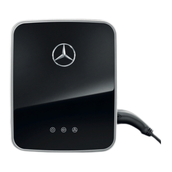
Summary of Contents for Mercedes-Benz 3W72M2
- Page 1 Mercedes-Benz Wallbox Installation manual for specialist electrical contractors...
- Page 2 Mercedesstraße 137 70327 Stuttgart, Germany In case of technical questions, please contact your local Mercedes-Benz technical support. This manual, in its entirety or in parts, must not be reproduced, stored electronically or otherwise transmitted electronically, electrically, mechanically, optically, chemically, by photocopy or as an audio recording without express written permission.
- Page 3 Identifying your model variant compliance declaration General requirements of the Glossary & Definitions installation site Trademarks Requirements for the power supply Intellectual Property & Copyright Mechanical installation of the Disposal advice mounting plate Mains Connection Schemes Taking the wallbox into operation Mercedes-Benz Wallbox...
-
Page 5: Important Information
The model variants of the Mercedes-Benz Wallbox can be identified by the product labels on the wallbox. These labels state the Mercedes-Benz product identification number (exterior underside) as well as the ABL model number (interior electronic components cover), but are identical regarding technical specifications. -
Page 6: General Safety Information
Only use accessories intended and sold for the device by Mercedes-Benz. • Do not operate this wallbox in close vicinity to running water or water jets: However, the Mercedes-Benz Wallbox is suffi- • ciently protected against water splashes and sprays according to IP54. -
Page 7: General Product Information
Should a malfunction occur with your wallbox, please first read the sections regarding “Error detection and solutions” on page 13. Should the fault or malfunction recur and still not be able to be resolved, please contact your local Mercedes-Benz technical support. -
Page 8: Notes Regarding Installation
Notes regarding installation Please observe the following instructions for the installation of your Mercedes-Benz Wallbox: The device must always be connected to the protective earth conductor of your electricity supply. The protective earth con- • nection will be made and checked by the installing contractor. After installation, only specialist electrical contractors may make changes. -
Page 9: Preparations, Installation And Taking Into Operation
Introducing the product The Mercedes-Benz Wallboxes are entirely manufactured in Germany and at all times comply with the regulations and norms for the charging of electric vehicles applicable throughout Europe according to IEC 61851-1, Mode 3 – please also refer to the section on”Guidelines &... -
Page 10: General Requirements Of The Installation Site
General requirements of the installation site Your Mercedes-Benz Wallbox is an electrical device and is therefore subject to particular requirements for indoor and outdoor installation. In selecting the installation site, you must consider the following points: Consider all local regulations for electrical installations, fire protection and accident prevention. -
Page 11: Requirements For The Power Supply
Requirements for the power supply The following standards must always be considered for the electrical installation of the Mercedes-Benz Wallbox: All regulatory requirements for low voltage installations according to IEC 60364-1 and IEC 60364-5-52 apply. - Page 12 Four 6 x 25 (TX25 bit) screws for fixing the wallbox housing to the mounting plate (included) • If required: Wall plugs suitable for the mounting substrate (included: 10 x 50 nylon wall plugs) • Spirit level if required (not included) •...
- Page 13 9. The wallbox includes three custom sealing membranes for the openings in the lower part of the wallbox: Insert these and cut a slit into the large seal- ing membrane: Now insert the supply cable through this opening. Mercedes-Benz Wallbox | Preparations, installation and taking into operation...
- Page 14 10. Hang the wallbox onto the mounting plate by inserting the screw in the center of the upper part at the rear into the respective opening in the mounting plate: this already protects the wallbox from falling. 11. Now fix the wallbox to the mounting plate using the screwdriver (TX25 bit) and the four 6 x 25 screws included.
-
Page 15: Taking The Wallbox Into Operation
PLEASE NOTE! The Mercedes-Benz Wallbox is preset for a charging current of 16 A by the factory. Should your domestic power sup- ply provide a lower or higher charging current, you must reset the preset current for the wallbox accordingly before you replace the electronic components cover and then take the wallbox into operation. - Page 16 The internal check routine is indicated by the LEDs on the front of the Mercedes-Benz Wallbox as follows. LED display Description All three LEDs flash once … ... and then go out. Then, the blue LED (ancillary version) and the green LED...
-
Page 17: Error Detection And Solutions
Error detection and solutions Should a malfunction occur during operation of the Mercedes-Benz Wallbox, this is shown by the indicator LEDs on the lower part of the housing cover as an error code. To indicate certain operating states, the LEDs may... - Page 18 Solution: The wallbox automatically reinitiates the charging procedure every 60 seconds: If the error continued to occur, please contact your local Mercedes-Benz technical support. Charging vehicles that require ventilation during the charging procedure is not possible with the Mercedes-Benz Wallbox.
- Page 19 Solution: Charging operations can continue, but the charging output will be reduced. If the error repeats or occurs perma- nently, take the wallbox out of operation (see “Taking the product out of and back into operation” on page 20) and contact your local Mercedes-Benz technical support. Mercedes-Benz Wallbox...
-
Page 20: Setup And Testing Modes
Setup and testing modes If a lower or higher charging current is provided by the domestic power supply, the factory preset for the Mercedes-Benz Wall- box (16 A) can be altered in setup mode via the internal rotary encoders. However, the rated current indicated on the product label must not be exceeded under any circumstances. - Page 21 Please follow these steps to change the maximum charging current setting of your Mercedes-Benz Wallbox: Working step LED status Note 1. Switch off the power supply for the wall- box via the upstream MCB(s) and RCCB. 2. Remove the internal electronic compo- On the S1 rotary encoder, select the nents cover.
- Page 22 Testing mode During initial setup and during later operation, you can check the settings of the Mercedes-Benz Wallbox in testing mode if there is no vehicle available. To do so, proceed as follows: Working step LED status Note 1. Switch off the power supply for the wall- box via the upstream MCB(s) and RCCB.
- Page 23 It is therefore recommended 0x09 not to make any changes and to generally leave the S3 rotary encoder in the 0 position. 0x0A 0x0B 0x0C 0x0D 0x0E 0x0F Mercedes-Benz Wallbox | Error detection and solutions...
-
Page 24: Taking The Product Out Of And Back Into Operation
Mercedes-Benz technical support. If the error can still not be resolved, repairs must be carried out. For this purpose, you must take the wallbox out of operation, uninstall it and return it via Mercedes-Benz technical sup- port. -
Page 25: Technical Specifications
477.9 x 376.4 x 32 mm (H x W x D) Maximum elevation ≤ 2,000 m AMSL (above mean sea level) Weight per unit incl. mounting plate ca. 14 kg Weight per unit w/o mounting plate ca. 13 kg Mercedes-Benz Wallbox | Appendix... -
Page 26: Scale Drawings And Dimensions
Scale drawings and dimensions The Mercedes-Benz Wallbox is delivered fully assembled and checked. All dimensions as well as the mounting points are indicated in the scale drawings below. Mounting plate Plan and elevation (all dimensions in mm) 376,4... -
Page 27: Contact Chart Type 1/Type 2
Wallbox with fixed charging cable Plan and elevation (all dimensions in mm) Contact chart Type 1/Type 2 L2/N Type2 Type1 Mercedes-Benz Wallbox | Appendix... -
Page 28: Guidelines & Norms
IP 54 splashing water CE certification and compliance declaration The Mercedes-Benz Wallbox carries the CE mark. The associated compliance declaration is available for download in electronic format at www.yourwallbox.de. Glossary & Definitions In the following, important abbreviations and terms used in this manual are explained. -
Page 29: Trademarks
European Union: Please inquire with your local authorities regarding proper disposal. The materials are recyclable as marked. By re-using, recycling or through other forms of processing obsolete devices, you make an important contribution to environmental protection. Mercedes-Benz Wallbox | Appendix... -
Page 30: Mains Connection Schemes
Mains Connection Schemes Local Local voltage Country Phase L1 Phase L2 Phase L3 Neutral 1-ph 3-ph frequency (domestic applications) Albania 50 Hz 230 / 400 V Argentina 50 Hz 220 / 380 V Australia 50 Hz 230 / 400 V Azerbaijan 50 Hz 230 / 400 V Bahrain 50 Hz 230 / 400 V 110 / 220 V... - Page 31 Local Local voltage Region Country Phase L1 Phase L2 Phase L3 Neutral 1-ph 3-ph frequency (domestic applications) Europe 50 Hz 230 / 400 V (without Norway and UK) 110 V Norway 50 Hz 230 / 400 V 50 Hz 240 / 415 V Mercedes-Benz Wallbox | Appendix...
- Page 32 The manufacturer may have made minor technical modifications to the product after publication of this instruction manual. This may also have led to minor discrepancies in the appearance of the product. Any color differences are a result of the printing process. Daimler AG, Mercedesstr.
Need help?
Do you have a question about the 3W72M2 and is the answer not in the manual?
Questions and answers