Table of Contents
Advertisement
Quick Links
control – motion –
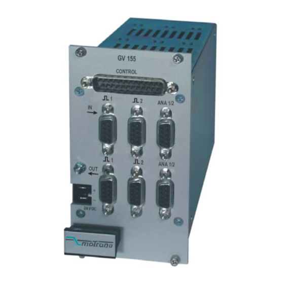
Electronic Cross Switchers for Encoder Signals
• 2 x 2 Cross matrix switch for encoders RS422 (A, /A, B, /B, Z, /Z) or HTL 15-30V
• 2 x 2 Cross matrix switch for analogue signals +/- 10V
• Cascadable inputs and outputs
• Bounce-free electronic switching of all channels
• PLC compatible control inputs for source-to-target selection, signals inversion, line
inhibit and for/rev selection
• Closed 19" aluminum housing, 14TE wide and 3HE high.
Front connection via standard Sub-D-connectors
• Supply range 18...30VDC
• Also suitable for DIN rail mounting with option "SM150"
GV15502B_e.DOC / Mrz-08
interface
GV155, GV156
and Analogue Signals
Operating Instructions
motrona GmbH
Zwischen den Wegen 32
78239 Rielasingen - Germany
Tel. +49 (0)7731-9332-0
Fax +49 (0)7731-9332-30
info@motrona.com
www.motrona.com
Page 1 / 9
Advertisement
Table of Contents

Subscribe to Our Youtube Channel
Related Manuals for Motrona GV155


Summary of Contents for Motrona GV155
- Page 1 – motion – interface info@motrona.com www.motrona.com GV155, GV156 Electronic Cross Switchers for Encoder Signals and Analogue Signals • 2 x 2 Cross matrix switch for encoders RS422 (A, /A, B, /B, Z, /Z) or HTL 15-30V • 2 x 2 Cross matrix switch for analogue signals +/- 10V •...
- Page 2 • Regarding installation, wiring, environmental conditions, screening of cables and earthing, you must follow the general standards of industrial automation industry • - Errors and omissions excepted – Version: Description: GV15502B/ TJ/ Sep 03/ P1...7,2 GV155-1 renamed to GV156 Block diagram revised GV15502B_e.DOC / Mrz-08 Page 2 / 9...
-
Page 3: Table Of Contents
Table of Contents 1. Block Diagram....................4 2. Applications ....................5 3. Connecting Diagrams..................6 3.1. Encoder inputs GV155 and GV156 with TTL level..........6 3.2. Encoder inputs GV156 with HTL level (Option HTLIN1) ........6 3.3. Encoder outputs GV155 and GV156 ..............6 3.4. -
Page 4: Block Diagram
+/- 10V A A B B Z Z A A B B Z Z GV155: All encoder inputs and outputs are designed for TTL level (RS422 line driver signals). GV156: Encoder inputs are available with TTL/RS422 format (standard) or with HTL (15-30V) format against ordering information “Option HTLIN1”. -
Page 5: Applications
Often, there are also unacceptable screening and wiring problems when using relays. Use of GV155 or GV156 avoids any of these problems and allows proper and reliable switching of digital and analogue signals. There are 14 control inputs C1…C14 that can operate from mechanical switches or under PLC control. -
Page 6: Connecting Diagrams
3. Connecting Diagrams 3.1. Encoder inputs GV155 and GV156 with TTL level A +5,5Vout A +5,5Vout Encoder input 1 Encoder input 2 Both connectors: Sub-D-9, male on unit site 3.2. Encoder inputs GV156 with HTL level (Option HTLIN1) A +24Vout... -
Page 7: Control Inputs
High 15...30 V Sub-D-25 male on unit site *) Only with GV155, but not with GV156 4. Output Level Selection (GV156 only) To select the desired output level, please remove the right-hand side plate and set the DIL switch according to need:... -
Page 8: Technical Specifications
5. Technical Specifications Power supply : 18...30 V DC/ 300 mA Max. encoder frequency : 400 kHz (GV155), 300 kHz (GV156) Encoder propagation delay : 200 ns (GV155), 700 ns (GV156) Encoder Inputs : RS422, 5V / 10 mA (TTL) 15 –30 V / 10 mA / PNP (Option HTLIN1) -
Page 9: Dimensions
6. Dimensions 122,5 55,5 70,5 Vorderansicht Seitenansicht Front view Side view 70,5 Draufsicht Top view Rückansicht Rear view GV15502B_e.DOC / Mrz-08 Page 9 / 9...
Need help?
Do you have a question about the GV155 and is the answer not in the manual?
Questions and answers