Table of Contents
Advertisement
Advertisement
Table of Contents

Related Manuals for Adamson E12


Summary of Contents for Adamson E12
- Page 2 Directive 2006/42/EC: Machinery Directive 974-0001 E12 975-0001 E15 992-0007 E218 994-0001 E219 930-0004 E-Frame with Extender Beam 931-0009 E12/E15 - SpekTrix Underhang 938-0015 E12 Dolly 938-0004 E15 Dolly 938-0016 E218 Dolly 938-0020 E219 Dolly 938-0014 Dolly Stacking Legs E-Series | Declaration of Conformity...
- Page 3 Section A Warning & Safety Symbols Throughout this manual the potential risks are indicated by these symbols. WARNING TIP HAZARD PINCH POINT ATTENTION SAFETY RISK CAN CAUSE SEVERE ALWAYS MOVE LOADED IMPORTANT OPERATING DOLLY ON THE LONG EDGE PAY SPECIAL ATTENTION PERSONAL INJURY INSTRUCTIONS AT TENTION...
-
Page 4: Safety Precautions
• Utilice solamente los Rigging Frames y accesorios especificados • Schützen Sie die Verkabelung von auf geknickt. por Adamson o que vengan con el equipo original de Adamson. • Verwenden Sie nur mit den Flugrahmen / von Adamson • Este recinto acústico es capaz de generar fuertes campos angegebenen oder mit dem Lautsprechersystem verkauft Zubehör. - Page 5 Table of Contents Sections Introduction & Product Details 1.1 Overview 1.2 Predictive Software 1.3 E15 Spec Sheet 1.4 E12 Spec Sheet 1.5 E218 Spec Sheet 1.6 E219 Spec Sheet 1.7 Cardioid Subs System Configuration 2.0 E-Rack Description 2.1 E-Rack Overview 2.2 Configuration Example...
-
Page 6: Overview
1.1 Overview At Adamson, we believe that loudspeakers need to be built from the ground up. This means having total control over every aspect of the design and manufacturing process. The E-Series is the culmination of decades of research that has allowed us to deliver the highest performing, large format line array on the planet. -
Page 7: Predictive Software
Blueprint AV is a 2D & 3D modeling suite which offers a fast and intuitive work-flow, without sacrificing precision. The E-Series is included, along with all of Adamson’s other Line Array products. Design is simple and easy, yet complex simulation options are at your finger tips. -
Page 8: E15 Spec Sheet
Introduction & Product Details 1.3 E15 Spec Sheet The Adamson E15 is a 3 way, true line source enclosure, incorporat- ing proprietary transducer and waveguide technology which reduc- es weight and minimizes the footprint. The heart of the E15 is the E-Capsule, which is precisely engineered and constructed of lightweight aluminum. -
Page 9: E12 Spec Sheet
The Adamson E12 is a 3 way, true line source enclosure, incorporat- ing proprietary transducer and waveguide technology which reduc- es weight and minimizes its footprint. The heart of the E12 is the E-Capsule, which is precisely engineered and constructed of lightweight aluminum. -
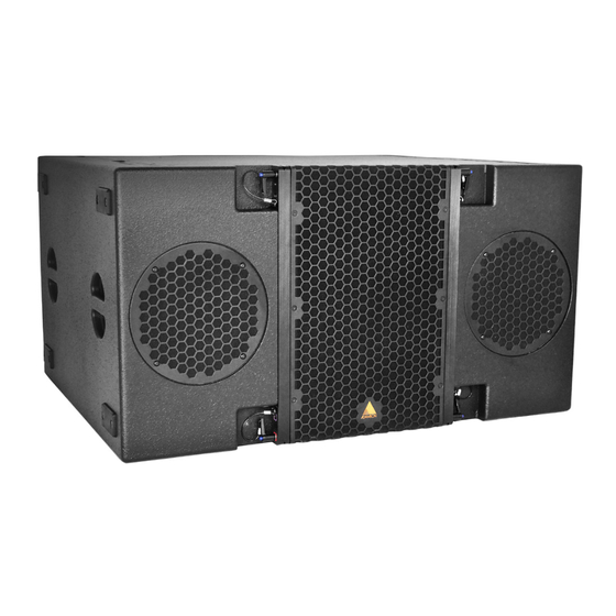
Page 10: E218 Spec Sheet
Introduction & Product Details 1.5 E218 Spec Sheet E218 The E218 subwoofer was developed to pair with the E12 or E15 enclosures. Two light-weight, long excursion ND18-S Kevlar Neodym- ium drivers which utilize Adamson’s Advanced Cone Architecture are mounted in an efficient band-pass subwoofer. The design achieves a remarkable reduction of the rearward radiated energy without dedicated cardioid setups and algorithms. -
Page 11: E219 Spec Sheet
Introduction & Product Details 1.6 E219 Spec Sheet E219 The E219 Subwoofer was developed to bolster the low-end of the E-Series line of products. The enclosure is loaded with two light weight, long excursion, 19” SD19 Kevlar Neodymium drivers utilizing Adam- son’s Advanced Cone Architecture and Symmetrical Drive Technology. -
Page 12: Cardioid Subs
Introduction & Product Details 1.7 Cardioid Subs Every Adamson subwoofer has specifically designed cardioid presets. Adamson utilizes three configurations ranging from a minimal footprint and minimized rear rejection to larger setups that eliminate virtually all audio energy behind the array. Please refer to the Lake Preset Loading Manual for further instructions. -
Page 13: System Configuration 2.0 E-Rack Description
• Up to three Lab.gruppen PLM 20K44 amplifiers (8 and 12-Channel versions available) • Adamson Audio Panel • Adamson AC Panel, 120 V or 230 V (region specific) • Cisco SG300-20 managed switch • Includes one Personal License per rack... -
Page 14: E-Rack Overview
System Configuration 2.1 E-Rack Overview Adamson has developed a unified rack solution configured to interface seamlessly with our line of Loudspeaker products. For more information on the E-Rack, please refer to the E-Rack brochure available on the Adamson Systems website. -
Page 15: Configuration Example
System Configuration 2.2 Configuration Example This example configuration demonstrates the efficiency of the system. For further information re- garding configurations, please refer to the Adamson Document E-Series Configuration Brochure. E12 | System Configuration Page 15... -
Page 16: Wiring Diagrams
System Configuration 2.3 Wiring Diagrams 3-way line source enclosure [974-0001] LF - 2x 12” ND12-S[940-0022], MF - 1x 7” YX7 [940-0020], HF - 1x 4”NH4 [140-0004] Autolock™ rigging system 3-way line source enclosure [975-0001] LF - 2x 15” ND14-L[940-0013], MF - 2x 7” YX7 [940-0020], HF - 2x 4”NH4 [140-0004] Autolock™... -
Page 17: Rigging
System Configuration 2.3 Wiring Diagrams E218 [992-0007] Subwoofer: LF - 2x 18” ND18-S [940-0023] Integrated rigging system E219 [994-0001] Subwoofer: LF - 2x 19” SD19-ND [940-0024] Integrated rigging system E-Series | Wiring Diagrams Page 17... -
Page 18: The 4 Stack Dolly
Rigging TIP HAZARD 3.0 The 4 Stack Dolly ALWAYS MOVE LOADED DOLLY ON THE LONG EDGE Transporting the 4 Stack Dolly There is a tip hazard when transporting a 4 stack on uneven ground or on a ramp. To avoid tipping the dolly, It should always travel with sides of the cabinet to the front or back. -
Page 19: Rigging Overview
The Autolock Rigging System™ The Autolock Rigging System™ is the main attachment for all of the points in the E15/E12 system. The idea is to only guide the latches to the right spot, where a spring-loaded bolt snaps into place, and is then secured with the very same lever by turning it into its lock down position. - Page 20 4.4° which slot should be pinned with the attached push-pin. The following rigging positions are equal to the following 8° 6° degrees for the E12 (Fig. 3) and the E15 (Fig.4). in enclosure in enclosure Fig. 3 Fig. 4 E-Series | Rigging...
- Page 21 IMPORTANT OPERATING INSTRUCTIONS The E-Frame with Extender Beam is designed for use with the E12 and E15 cabinets. It consists of a steel frame, paired with an extension beamof which there are several combination configurations. Always refer to Blueprint AV™ for correct rigging instructions.
- Page 22 Rigging 3.1 Rigging Overview ATTENTION IMPORTANT OPERATING INSTRUCTIONS For arrays with little to no incline, the extension beam centered will usually provide the best weight dispersion. Fig. 1 For arrays with negative incline, the extension beam positioned towards the back of the frame will provide the best weight dispersion.
- Page 23 The frame faces one direction while in stacking mode and is reversed when in hanging mode. If the E218/E219 and E12/E15 are to be flown in the same array, two frames are needed. Please refer to sections 3.10 and 3.11 for detailed descriptions of how to deploy the frame.
-
Page 24: Rear Rigging
Rigging 3.2 Rear Rigging ATTENTION IMPORTANT OPERATING INSTRUCTIONS Rear Autolock Rigging - Red Lever The 3 different modes of the red lever: 1. Closed (Locked) 2. Spring Mode 3. Open (Locked) In the ‘Closed’ mode (Fig. 1) the lever is in and turned upward or downward (both up and down lock the system - decide which way you’ll be using it, and close all the enclosures the same way for uniformity. -
Page 25: Front Rigging
Rigging 3.3 Front Rigging ATTENTION IMPORTANT OPERATING INSTRUCTIONS Front Autolock Rigging - Blue Lever The 3 different modes of the blue lever: 1. Closed (Locked) 2. Spring Mode 3. Open (Locked) ‘Closed’ (Fig. 1)- the lever is in and turned downward to lock the system. - Page 26 Rigging 3.3 Front Rigging ATTENTION IMPORTANT OPERATING INSTRUCTIONS Front Autolock Rigging - Black Lever There is only 1 mode of use for the black lever: The lever is pulled out and parallel to the ground in temporary ‘Open’ mode (Fig. 1)- this releases the rigging bars from inside the enclosure.
-
Page 27: Rigging Sticker Legend
* Stack pin slot is used when stacking the E15/E12 system, or needing a rigid flown array. (ie when the system is arrayed in a manner that gravity cannot sustain the desired angles). -
Page 28: Setting Angles
Rigging 3.5 Setting Angles ATTENTION IMPORTANT OPERATING INSTRUCTIONS Setting the angles on all 4-stacks and basic preparation. Before attaching cabinets together, use Blueprint AV™ to plan your cabinet angles for desired coverage. Prepare all the cabinet angles before beginning to attach and lift the array. The top cabinet, which attaches to the rigging frame is number 1, and the cabinets gain numerically as the descend. -
Page 29: Attaching The Rigging Frame
Rigging 3.6 Attaching the Rigging Frame PINCH POINT WARNING CAN CAUSE SEVERE SAFETY RISK PAY SPECIAL ATTENTION PERSONAL INJURY The rigging Frame contains 4 pins: 2 in the front which are fixed in place and 2 in the rear, one of which needs to be pinned manually using attached push pin. - Page 30 Rigging 3.6 Attaching the Rigging Frame PINCH POINT WARNING CAN CAUSE SEVERE SAFETY RISK PAY SPECIAL ATTENTION PERSONAL INJURY 6. Ensure the rear red pin that connects to the dolly on the bottom cabinet is in the open position. (Fig. 3) Fig.
-
Page 31: Consequent Arrays
Rigging 3.7 Consequent Arrays PINCH POINT WARNING CAN CAUSE SEVERE SAFETY RISK PAY SPECIAL ATTENTION PERSONAL INJURY Attaching the second and consequent arrays 1. Lift Frame with the attached 4 enclosures high enough to clear the next 4 -stack underneath. (they should all have their angles set) 2. - Page 32 Rigging 3.7 Consequent Arrays PINCH POINT WARNING CAN CAUSE SEVERE SAFETY RISK PAY SPECIAL ATTENTION PERSONAL INJURY 5. If dealing with a large amount of cabinets and high rigging points, its best to keep the lower stack pushed slightly back to allow for any spring in the motor and top rigging.
-
Page 33: Highly Curved Arrays
Rigging 3.8 Highly Curved Arrays PINCH POINT WARNING CAN CAUSE SEVERE SAFETY RISK PAY SPECIAL ATTENTION PERSONAL INJURY Connecting a 4 stack to a highly curved array When connecting a 4 stack of cabinets to a steep flown array, it may not be safe or practical to continue to lower the array to make the rear attachment (once the fronts are connected). -
Page 34: Lowering The Array
Rigging 3.9 Lowering the Array PINCH POINT WARNING CAN CAUSE SEVERE SAFETY RISK PAY SPECIAL ATTENTION PERSONAL INJURY To Lower a Steep Angled Array 1. Lower the array until it is just above the floor. (Fig. 1) 2. Make sure the rear red lever on the bottom box is set to “spring” mode to receive the dolly. -
Page 35: Rigging The E Sub
E-Series Subwoofer cabinets. The E-Frame Full Line has two modes; flying and stacking. A tray for the Adamson Laser Inclinometer exists at one end of the frame. If the tray is facing forward, the frame is in flying mode. If the tray is facing backwards, the frame is in stacking mode. -
Page 36: Attaching Tops To Subs
Plates is adjustable, follow what the Blueprint AV™ mechanical tab displays. (Fig. 2) Fig. 2 4. Set the E12/E15 red lever to “Spring” mode and place the cabinet on the rigging frame, confirm the rear rigging is locked. (Fig. 3) Fig. - Page 37 (Fig. 1) Fig. 1 4. Place E-Frame Full Line on the E12 and confirm the front rig- ging is locked. 5. Set the rear knob lever to 0 and lock in place using the push pin.
-
Page 38: Ground Stacking 4.0 Ground Stacking Legs
Dolly Stacking Legs (938-0014) Available as an accessory, the Ground Stacking Legs allow users to angle the E12 or E15 in positive or negative increments while situated on the E12 or E15 Dolly. 1. Make sure all wheel locks are engaged and the dolly is situated where the design has specified. -
Page 39: Truck Pack 5.0 Possible Configurations
91”, and a depth of ap- proximately 36”. 90.8" 2.3m 99.4" 92.9" 4x E12/E15 Symmetrical 2.5m 2.4m Four 4-high E12 dollies are packed front to back for a width of approximately 93”, and a depth of approximately 45”. 92.9" 99.4" 2.4m 2.5m 99.4" 92.9"...
Need help?
Do you have a question about the E12 and is the answer not in the manual?
Questions and answers