Table of Contents
Advertisement
Quick Links
The content in this manual has been carefully prepared and is believed to be accurate, but no
responsibility is assumed for inaccuracies.
User's Manual
Leadshine reserves the right to make changes without further notice to any products herein to
improve reliability, function or design. Leadshine does not assume any liability arising out of the
For
application or use of any product or circuit described herein; neither does it convey any license
DM422C
under its patent rights of others.
Leadshine's general policy does not recommend the use of its products in life support or aircraft
applications wherein a failure or malfunction of the product may directly threaten life or injury.
According to Leadshine's terms and conditions of sales, the user of Leadshine's products in life
support or aircraft applications assumes all risks of such use and indemnifies Leadshine against all
Fully Digital Stepping Drive
damages.
Version 1.0
©2009 All Rights Reserved
Attention: Please read this manual carefully before using the Drive!
©2009 by Leadshine Technology Company Limited.
All Rights Reserved
DOLD Mechatronik
info@dold-mechatronik.de
Sarach 10 – D-77790 Steinach
www.dold-mechatronik.de
Telefon: +49 7832 / 9744670
Advertisement
Table of Contents

Summary of Contents for Leadshine Technology DM422C
- Page 1 Leadshine against all Fully Digital Stepping Drive damages. Version 1.0 ©2009 All Rights Reserved Attention: Please read this manual carefully before using the Drive! ©2009 by Leadshine Technology Company Limited. All Rights Reserved DOLD Mechatronik info@dold-mechatronik.de Sarach 10 – D-77790 Steinach www.dold-mechatronik.de...
- Page 2 Contents Contents Dynamic current setting ................10 Table of Contents Standstill current setting................10 1. Introduction, Features and Applications..............1 8. Wiring Notes ......................10 Introduction ......................1 9. Typical Connection....................11 Features ......................... 1 10. Sequence Chart of Control Signals ............... 11 Applications ......................
-
Page 3: Introduction, Features And Applications
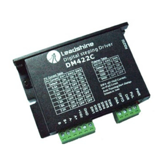
Electrical Specifications (T = 25℃/77℉) Introduction DM422C The DM422C is a versatility fully digital stepping Drive based on a DSP with advanced control Parameters Typical Unit algorithm. The DM422C is the next generation of digital stepping motor controls. It brings a Output current 2.2 (1.6 RMS) -
Page 4: Specifications
Environment Selecting Active Pulse Edge and Control Signal Mode 0℃-50℃ (32℉-122℉) Ambient Temperature The DM422C supports PUL/DIR and CW/CCW modes and pulse active at rising or falling edge. See 40%RH-90%RH Operating Environment Humidity more information about these settings in Section 13. Default setting is PUL/DIR mode and rising 70℃... -
Page 5: Connecting The Motor
4 lead motors are the least flexible but easiest to wire. Speed and torque will depend on winding The DM422C uses opto-couplers to increase noise immunity and interface flexibility. If the inductance. In setting the Drive output current, multiply the specified phase current by 1.4 to opto-couplers’... - Page 6 DM422C Digital Stepping Driver Manual V1.0 6. Power Supply Selection The DM422C can match medium and small size stepping motors (from NEMA frame size 14 to 23) made by Leadshine or other motor manufactures around the world. To achieve good driving performances, it is important to select supply voltage and output current properly.
-
Page 7: Info@Dold-Mechatronik.de
DM422C Digital Stepping Driver Manual V1.0 DM422C Digital Stepping Driver Manual V1.0 it may also cause over-voltage protection or even Drive damage. Therefore, it is suggested to choose motor coils will significantly change resulting inductance and resistance, it is therefore important to only sufficiently high supply voltage for intended applications, and it is suggested to use power set Drive output current depending on motor phase current, motor leads and connection methods. -
Page 8: Connector P1 Configurations
Low level width not less than 7.5µs. 11. Protection Functions To improve reliability, the Drive incorporates some built-in protection functions. The DM422C uses one RED LED to indicate what protection has been activated. The periodic time of RED is 3 s (seconds), and how many times the RED turns on indicates what protection has been activated. -
Page 9: Frequently Asked Questions
DM422C Digital Stepping Driver Manual V1.0 DM422C Digital Stepping Driver Manual V1.0 Problem Symptoms and Possible Causes Phase Error Protection Motor power lines wrong & not connected will activate this protection. RED LED will turn on four Symptoms Possible Problems times within each periodic time (3 s). - Page 10 This section will provide an overview of connection and basic setup instructions for Leadshine’s digital stepping Drive DM422C using the ProTuner software. These instructions will walk you through the following steps necessary to start up your Drive and motor. This section is intended for setting up the Drive with the ProTuner.
- Page 11 DM422C Digital Stepping Driver Manual V1.0 DM422C Digital Stepping Driver Manual V1.0 Figure 14: Installation folder settings Figure 16: Installation information summarization Figure 15: Shortcut folder setting Figure 17: Installing the ProTuner Set the “Shortcut Folder” in Figure 15 and continue to install the ProTuner by following Figure 16 and Figure 17.
- Page 12 Option Turn on the power supply, the green (Power) LED will light. The DM422C has default parameters The user can choose three drop-down menus by clicking “Option”, including Com Config, stored in the Drive. If the system has no hardware and wirings problem, the motor should be locked SaveToDrive and Exit.
- Page 13 DM422C Digital Stepping Driver Manual V1.0 DM422C Digital Stepping Driver Manual V1.0 Exit: Exit the ProTuner. Com Config Window Figure 21: RS232 communication configuration window Figure 22: Current Tuning window Serial Port: Select the serial communication port to which the Drive is connected. The factory default Ki: Integral Gain.
-
Page 14: Connecting The Motor
The DM422C Drive provides robust anti-resonance control to stop the vibrations and maintain equilibrium. However, if the user does not want to tune the current loop after changing a different stepping motor, This feature requires that the Drive be configured with respect to the total inertia in the system. - Page 15 DM422C Digital Stepping Driver Manual V1.0 DM422C Digital Stepping Driver Manual V1.0 ResonanceArea: Parameters for 3 resonance area. Usually between 2.4rps and 4.8rps. Default making it more difficult to find proper adjustment values. Optimum AMP(s) and Phase(s) values may Amp3 and Phase3 values are 128.
-
Page 16: Over-Current Protection
DM422C Digital Stepping Driver Manual V1.0 DM422C Digital Stepping Driver Manual V1.0 exceeds 16A. OverVoltage: Over-voltage Protection. When power supply voltage exceeds 42±1 VDC, protection will be activated. PhaseErr: Phase Error Protection. Motor power lines wrong & not connected will activate this protection.