
Related Manuals for Alpha ATS-216


Summary of Contents for Alpha ATS-216
- Page 1 ALPHA Automated Transfer Switch Operating Manual Rev 1.21 The original of this document is drawn up in English language ATS Manual | Rev 1.21 | © Alpha Technologies GmbH 2013...
-
Page 2: Table Of Contents
Table of Contents Safety Instructions .................. 2 Product Description ................3 Installation and Operating Instructions ........... 4 3.1. Packaging ....................4 3.2. Choose an installation location ............... 4 3.3. Product Introduction ................5 3.4. Product Installation and Operation ............10 Troubleshooting .................. -
Page 3: Safety Instructions
Safety Instructions Product Description The ATS (Automatic Transfer Switch) features two independent power supply SAVE THESE INSTRUCTIONS. This manual contains important circuits supplying power to the load (as shown in Figure 1 below). In the event of a instructions that should be followed during installation and power failure in the main circuit, the ATS automatically switches to the other circuit maintenance of the ATS. -
Page 4: Installation And Operating Instructions
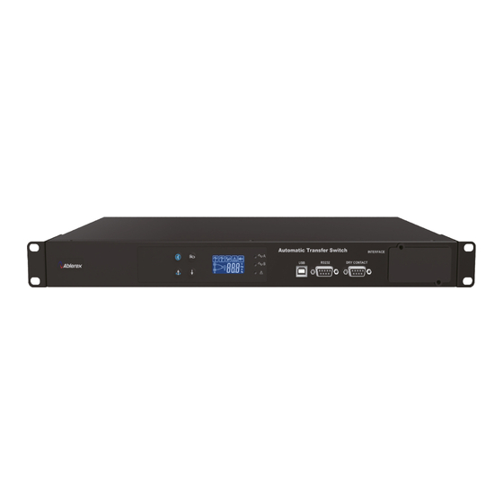
USB cable x1 pcs ○, CD (monitoring software, Setting tool and user manual) x1 pcs ○, Backplate and screws x1 set ○, Power cable x2 pcs ( Available only for ATS-216 models) Item Description/function 3.2. Choose an installation location ○ ,1 Mute button... - Page 5 3.3.2. LCD 3.3.3. Rear Panel ATS-216(230V-16A) ATS-120(120V-20A) ATS- 232(230V-32A) Symbol Description/function Input A error or power failure Input B error or power failure ATS- 130(120V-30A) Overload System malfunction or abnormal Alarm on ○ ○ ,1 Power input (B) ,5 Output socket Alarm off ○...
- Page 6 3.3.4. Interface 3.3.4.3. Dry Contact The ATS provides three communication ports and one external The ATS provides five user configurable dry contacts for customized communication slot (optional) for the user. features. The capacity of each contact is 24Vdc/1A, additional information is provided in Appendix A.
-
Page 7: Product Installation And Operation
3.4.2. Boot up 3.4. Product Installation and Operation Once input power is connected, the ATS automatically boots up. The LCD display 3.4.1. Installation Procedure: during boot is as shown in Figure 4 and all LEDs ( ) are lit. LCD 1. -
Page 8: Troubleshooting
Troubleshooting System Specifications If your ATS is not working normally, use the following status and troubleshooting table to make the appropriate adjustments. Please contact your Model ATS-120 ATS-130 distributor as soon as possible if the issue cannot be resolved. Input Issue Possible reason Solution... -
Page 9: Appendix A. Dry Contacts Available For Configuration
Appendix A. Dry contacts available for configuration Model ATS-216 ATS-232 Event Code Input Source A no power Er01 200/208/220/230/240 Input voltage Source B no power Er02 (+/-5%/10%/15%/20%) Source A voltage abnormal Er03 Input voltage range 150Vac~300Vac Source B voltage abnormal... - Page 11 192321342002001...
Need help?
Do you have a question about the ATS-216 and is the answer not in the manual?
Questions and answers