Table of Contents
Advertisement
Quick Links
Advertisement
Table of Contents

Related Manuals for Alpha Cordex HP CXRF 48-3.0kW


Summary of Contents for Alpha Cordex HP CXRF 48-3.0kW
- Page 1 Cordex HP 2.4kW / 3.0kW Switched Mode Rectifier System Models: Cordex HP CXRF 48-3.0kW ® Cordex HP CXRF 48-2.4kW ® User Guide ID: 0100037-J0 Effective: 05/2021 Read this manual carefully. Learn how to protect your equipment from damage and fully understand its functions.
- Page 2 The material contained in this document is for information only and is subject to change without notice. While reasonable efforts have been made in the preparation of this document to assure its accuracy, Alpha Technologies assumes no liability resulting from errors or omissions in this document, or from the use of the information contained herein. Alpha Technologies...
-
Page 3: Table Of Contents
Contents 1. Safety ....................4 1.1 Safety symbols ........................... 4 1.2 General safety ..........................4 1.3 Mechanical safety ........................5 1.4 Electrical safety .......................... 5 1.5 Battery safety ..........................5 2. Introduction ..................6 2.1 Scope of the manual ........................6 2.2 Product overview ........................6 2.3 Part numbers .......................... - Page 4 6.9 System startup ......................... 33 7. Wiring ....................34 7.1 Installation notes ........................34 7.2 Calculating output wire size requirements ................34 7.3 Grounding ..........................35 8. Rectifier modes and factory defaults..........36 8.1 Rectifier modes ........................36 8.2 Factory ranges and defaults ....................37 9. Maintenance .................38 9.1 ...
-
Page 5: Safety
Keep it in a safe place. Review the drawings and illustrations contained in this manual before proceeding. If there are any questions regarding the safe installation or operation of this product, contact Alpha Technologies or the nearest Alpha representative. Save this document for future reference. 1.1 Safety symbols To reduce the risk of injury or death, and to ensure the continued safe operation of this product, the following symbols have been placed throughout this manual. -
Page 6: Mechanical Safety
User Guide Cordex HP 2.4kW / 3.0kW Modular Switched Mode Rectifier 1.3 Mechanical safety • Keep hands and tools clear of fans. Fans are thermostatically controlled and switch on automatically. • Power supplies can reach extreme temperatures under load. • Use caution around sheet metal components and sharp edges. -
Page 7: Introduction
Cordex HP 2.4kW / 3.0kW Modular Switched Mode Rectifier User Guide 2. Introduction 2.1 Scope of the manual This manual explains the installation, interconnection, and operation of: • Cordex HP 3.0kW rectifier systems • Cordex HP 2.4kW rectifier systems. 2.2 Product overview A complete rectifier system consists of one or more power modules in a common shelf enclosure. The shelf has connections for AC inputs, DC output, and system communications. The wide AC input operating range for global installations and wide operating temperature ranges for installation in uncontrolled environments along with high efficiency (>96%) reduces the carbon footprint and the operating expenses. -
Page 8: Part Numbers
User Guide Cordex HP 2.4kW / 3.0kW Modular Switched Mode Rectifier 2.3 Part numbers The product, options, and accessories can be ordered by using the part numbers in the following tables. 2.3.1 Cordex HP 3.0kW rectifier Description Part numbers 23 inch 1RU universal mount 15000W shelf* 0300216-001 (shelf/slot ID supported) •... -
Page 9: Specifications
Cordex HP 2.4kW / 3.0kW Modular Switched Mode Rectifier User Guide 3. Specifications 3.1 Cordex HP 3.0kW rectifier Table A — Cordex 3.0kW rectifier specifications Electrical Input specifications Nominal input 208 to 277Vac Full power 187 to 300Vac Input operational 90 to 300Vac Input extended high 277 to 300Vac reduced input PF Input extended low... - Page 10 User Guide Cordex HP 2.4kW / 3.0kW Modular Switched Mode Rectifier Wide band 10kHz to 100MHz <180mVpk-pk Reliability MTBF 623,860 hours Telcordia SR-332 Issue 3 Method 1 Case 3, Parts Count Method, Quality Level II Ambient temperature 30°C, Environment: Ground Fixed, Controlled, 100% Duty Cycle, Full Load (Remarks) • Devices are assumed to be operating at ambient temperature and 50% rated electrical stress. However, the operating point and temperature of selected critical components was measured and included in the model for improved accuracy.
- Page 11 Cordex HP 2.4kW / 3.0kW Modular Switched Mode Rectifier User Guide Communications ports CAN: interface to control rectifiers and smart peripherals Shelf ID: interface to connect to bay ID module 19 inch 1RU universal mount 12,000W shelf P/N 0300228-001 (shelf/slot ID supported) Number of rectifiers Four Cordex HP 48-3.0kW rectifiers Nominal AC input current 120Vac;...
-
Page 12: Cordex Hp 2.4Kw Rectifier
User Guide Cordex HP 2.4kW / 3.0kW Modular Switched Mode Rectifier 3.2 Cordex HP 2.4kW rectifier Table B — Cordex 2.4kW rectifier specifications Electrical Input voltage Nominal 208 to 277Vac Operating 90 to 310Vac Extended 90 to 187Vac (de-rated power) Input frequency 44 to 66Hz Power 2400W continuous (1200W output at 120Vac Input) - Page 13 Cordex HP 2.4kW / 3.0kW Modular Switched Mode Rectifier User Guide 3.2.1 Cordex 48-2.4kW rectifier shelves 23 inch 1RU universal mount 12,000/15,000W shelf P/N 0300057-001 Number of rectifiers Five Cordex HP 48-2.4kW/3.0kW rectifiers Nominal AC input current 120Vac; 23A (per feed); 50/60Hz (two modules per feed) 208 to 277Vac; 25 to 19A (per feed); 50/60Hz Recommended input feeder breakers 40A per feed for rectifier pairs with nominal 120, 208, 240, 277 Vac (three feeds per shelf)
-
Page 14: Features
User Guide Cordex HP 2.4kW / 3.0kW Modular Switched Mode Rectifier 4. Features 4.1 Cordex HP 3.0kW rectifier 4.1.1 Front panel LEDs The front panel LEDs indicate the rectifier status summary and patterned response to Locate Module command. The red LED is on during an active Module Fail alarm if the module is unable to source power due to a fault condition. Refer to the relevant controller manual for fault details. - Page 15 Cordex HP 2.4kW / 3.0kW Modular Switched Mode Rectifier User Guide 4.1.4 Over temperature protection Blockage or obstruction to the air flow can result in the internal temperature to rise and reduce the output power or even shut down the rectifier. The rectifier will resume normal operation when the temperature reduces to a safe level. Over temperature shut down can also occur when a fan failure has occurred. The rectifier; to protect itself from ambient over temperature scenarios; will limit its output power. 3.0kW Output Power vs. Temperature 120% -40, 100% 0, 100% 100% 55, 100% 65, 67% 75, 20% 75, 0%...
- Page 16 User Guide Cordex HP 2.4kW / 3.0kW Modular Switched Mode Rectifier 4.1.8 Start delay The rectifier modules are equipped with a delay timer to stagger-start a series of modules. When multiple modules and multiple shelves, part of a larger system are used in conjunction with a controller, a start delay prevents all rectifiers from starting at the same time and causing an inrush on the utility. The default start delay is set to 1 second and can be adjusted up to 250 seconds on the Cordex HP controller. The built-in timer delays the switching on of the module by the start delay interval (up to 250 seconds), which is set in the controller.
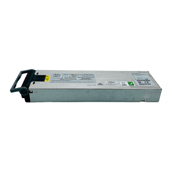
- Page 17 Cordex HP 2.4kW / 3.0kW Modular Switched Mode Rectifier User Guide 4.1.13 Mechanical An integral handle provides a means to both insert and remove the rectifier as well as locking the rectifier in place. 4.1.14 Firmware update The rectifier module should have its operating firmware updated through the Cordex HP controller. Using the latest firmware will ensure the controller has the latest features and that all corrections have been applied. NOTE The 3.0kW rectifier requires AC input power to be connected to perform the firmware update. 4.1.15 Distribution Bulk • 23 inch 1RU universal mount P/N 0300057-001 (2.4kW compatible), 0300216-001 (shelf ID support) •...
- Page 18 User Guide Cordex HP 2.4kW / 3.0kW Modular Switched Mode Rectifier 4.1.17 Internal CAN bus A CAN bus is used to transmit all alarm and control functions between the controller and rectifier shelves. Two CAN serial ports (modular jacks), are located on the left side of the rectifier shelf as viewed from the front. The CAN bus can be daisy-chained from shelf to shelf (CAN 1 of one shelf to CAN 2 of another). The last shelf is terminated using a CAN terminator.
-
Page 19: Cordex Hp 2.4Kw Rectifier
Cordex HP 2.4kW / 3.0kW Modular Switched Mode Rectifier User Guide 4.2 Cordex HP 2.4kW rectifier 4.2.1 Front panel LEDs The front panel LEDs indicate the rectifier status summary and patterned response to Locate Module command. The red LED is on during an active Module Fail alarm if the module is unable to source power due to a fault condition. Refer to the relevant controller manual for fault details. - Page 20 User Guide Cordex HP 2.4kW / 3.0kW Modular Switched Mode Rectifier 4.2.5 Over temperature protection Blockage or obstruction to the air flow can result in the internal temperature to rise and reduce the output power or even shut down the rectifier. The rectifier will resume normal operation when the temperature reduces to a safe level. Over temperature shut down can also occur when a fan failure has occurred. 4.2.6 Wide AC range The rectifier delivers up to 2400W of power between 187Vac and 310Vac input voltage. The rectifier can deliver up to 1200W between 90Vac and 187Vac. During start up the rectifier begins to provide power for input voltage >95 Vac and shuts down if the input voltage ...
- Page 21 Cordex HP 2.4kW / 3.0kW Modular Switched Mode Rectifier User Guide 4.2.12 High voltage shutdown (HVSD) This feature protects the load from over-voltages originating in the rectifiers. The offending rectifier module is shut down when a high output voltage condition occurs. The red Alarm (Module Fail) LED will illuminate. The module will restart automatically. However, if more than three over-voltage conditions occur within one minute, the module will latch off and remain shut down until it is reset by restarting the rectifier via the controller.
- Page 22 User Guide Cordex HP 2.4kW / 3.0kW Modular Switched Mode Rectifier 4.2.15 Controller The 2.4kW rectifier shelf is designed to operate with the CXCR/CXCP controller (rack/panel) or the Cordex HP controller. A controller adds the following capabilities to the rectifiers: • Local and remote communications and monitoring • User definable alarms • Daily logging of events and system statistics • Load sharing • Power save NOTE The 2.4 kW shelf is also designed to operate without a Cordex controller; however load balancing among the rectifiers won't be as efficient, particularly at lower input voltages.
-
Page 23: Inspection
If any damage is observed, contact the carrier immediately. Continue the inspection for any internal damage. In the unlikely event of internal damage, inform the carrier and contact Alpha Technologies for advice on the impact of any damage. -
Page 24: Installation
User Guide Cordex HP 2.4kW / 3.0kW Modular Switched Mode Rectifier 6. Installation The equipment is suitable for installation in Network Telecommunication Facilities. WARNING! This system is designed to be installed in a restricted access location that is inaccessible to the general public. -
Page 25: Assembly And Mounting
Cordex HP 2.4kW / 3.0kW Modular Switched Mode Rectifier User Guide 6.4 Assembly and mounting 6.4.1 Mounting and grounding a rectifier shelf WARNING! Ensure that the power is switched off by switching off breakers and removing battery line fuses, turn off battery breakers before attempting work on the wiring. Use a voltmeter to verify the absence of a voltage. -
Page 26: Dc Output Connections - Bulk Distribution
User Guide Cordex HP 2.4kW / 3.0kW Modular Switched Mode Rectifier 6.5 DC output connections - bulk distribution WARNING! Do not complete the final live connections to the battery. Leave open and insulate the final connections or remove the battery fuses. Switch off the battery contacts if used. The DC output wire must be UL approved XHHW or RHH/RHW (for Canadian users RW90; for European users, ... - Page 27 Cordex HP 2.4kW / 3.0kW Modular Switched Mode Rectifier User Guide 6.5.1 Busbar connection Multiple shelves can be connected directly to customers’ vertical busbar. 1. Remove the bolts and washers at both positive and negative output bars. Bolts are 3/8-16 × 1", and can accommodate up to 1/4" thick busbar. 2. Use fasteners removed from the previous step to secure the vertical busbars to shelf positive and negative output bars. Install all fasteners finger tight, then apply 27.12Nm (20 ft-lbf) torque to each bolt. NOTE In a power system, up to five rectifier shelves may be stacked before a gap must be left for adequate cooling of the rectifiers and shelves.
- Page 28 User Guide Cordex HP 2.4kW / 3.0kW Modular Switched Mode Rectifier 6.5.3 DC output connections - single component distribution 2.4kW rectifier systems only When attaching cables directly to the output bars, use appropriately sized cables terminated with crimp lugs with M6 bolts on 5/8" centers. ...
-
Page 29: Ac Wiring 23 Inch Shelf
Cordex HP 2.4kW / 3.0kW Modular Switched Mode Rectifier User Guide 6.6 AC wiring 23 inch shelf 6.6.1 AC feeder protection/sizing To maximize system reliability it is recommended that, each power module be fed from a dedicated protection feeder breaker located at the AC distribution panel. The feeder breaker can also act as the disconnect device for the connected module. -
Page 30: Ac Wiring 19 Inch Shelf
User Guide Cordex HP 2.4kW / 3.0kW Modular Switched Mode Rectifier 6.7 AC wiring 19 inch shelf For the 19 inch shelf, AC wiring is fed separately to each of the four rectifiers. 6.7.1 AC feeder protection/sizing To maximize system reliability it is recommended that, each power module be fed from a dedicated protection feeder breaker located at the AC distribution panel. The feeder breaker can also act as the disconnect device for the connected module. -
Page 31: Communication Cabling (Optional)
Cordex HP 2.4kW / 3.0kW Modular Switched Mode Rectifier User Guide 6.8 Communication cabling (optional) 6.8.1 CAN serial ports (rectifier shelf) Two CAN serial ports (modular jacks), are provided for communications with Cordex controllers and other CAN- enabled equipment. These are located on the left side of the rectifier shelf as viewed from the front. 1. Daisy-chain from shelf to shelf (CAN 1 of one shelf to CAN 2 of another). 2. - Page 32 User Guide Cordex HP 2.4kW / 3.0kW Modular Switched Mode Rectifier 6.8.2 Shelf ID connection (3.0kW rectifier systems only) The Shelf ID module can be used for loading individual rectifiers when multiple shelves are used in multiple bays. Rack-mounted Shelf ID Bay ID 1 (manually set) J2 J3 J4 J5 J6 J7 J8 J9 Bay ID 1 Bay ID 1 Shelf ID 1 Shelf ID 2 Cordex HP CAN driver Rectifier...
- Page 33 Cordex HP 2.4kW / 3.0kW Modular Switched Mode Rectifier User Guide 6.8.3 Signal wiring connections to L-ADIO board (optional) For terminal block connections, the recommended wire sizes are 0.823 to 0.129mm (18 AWG to 26 AWG) for the temperature range of 0 to 50 degrees Celsius (32 to 122 degrees Fahrenheit) (as per UL/CSA). CAUTION! To reduce risk of fire, use only 0.129 mm²...
-
Page 34: System Startup
User Guide Cordex HP 2.4kW / 3.0kW Modular Switched Mode Rectifier 6.9 System startup Visually inspect the installation thoroughly. After completing the system installation and power system wiring, perform the following startup and test procedure to ensure proper operation: 6.9.1 Check system connections 1. -
Page 35: Wiring
Cordex HP 2.4kW / 3.0kW Modular Switched Mode Rectifier User Guide 7. Wiring This chapter provides cabling details and notes on cable sizing for DC applications with respect to the product. WARNING! Ensure that the power is switched off by switching off rectifiers and removing battery line fuses, turn off battery breakers before attempting work on the wiring. -
Page 36: Grounding
User Guide Cordex HP 2.4kW / 3.0kW Modular Switched Mode Rectifier Table C — Cable size equivalents (AWG to Metric) Cable size Circular mils Square millimeters Equivalent metric cable 313 MCM (or kcmil) 313600 150 or 185 350 MCM (or kcmil) 350000 177.36 373 MCM (or kcmil) -
Page 37: Rectifier Modes And Factory Defaults
Cordex HP 2.4kW / 3.0kW Modular Switched Mode Rectifier User Guide 8. Rectifier modes and factory defaults 8.1 Rectifier modes There are two main rectifier modes: output voltage mode and the output current/power mode. 8.1.1 Output voltage modes Voltage modes are under software control, and can be used to directly adjust the output voltage. The qualification of “under software control” is made because there are processes that occur in the rectifier that can change the output voltage that do not adjust the output voltage directly, for example, if the rectifier has reached the current limit. Table F lists output voltage modes and a description of when they are active. These modes can be set via the controller. -
Page 38: Factory Ranges And Defaults
User Guide Cordex HP 2.4kW / 3.0kW Modular Switched Mode Rectifier 8.2 Factory ranges and defaults Table H shows the rectifier settings, ranges, and default values. Changes are made through the controller interface. Table H — Rectifier factory ranges and defaults Setting Range (minimum to maximum) Default Float (FL) Voltage 47.5V to 58V Equalize (EQ) Voltage 49.8V to 60V Battery Test (BT) Voltage 44V to 52V... -
Page 39: Maintenance
Cordex HP 2.4kW / 3.0kW Modular Switched Mode Rectifier User Guide 9. Maintenance Although very little maintenance is required with Alpha systems, routine checks and adjustments are recommended to ensure optimum system performance. Qualified service personnel should do the repairs. The following table lists a few maintenance procedures for this system. These procedures should be performed at least once a year. -
Page 40: Replacing A Rectifier Module Via Cordex Controller
User Guide Cordex HP 2.4kW / 3.0kW Modular Switched Mode Rectifier 9.2 Replacing a rectifier module via Cordex controller The rectifier is plug and play. When a rectifier module is added to the system, the controller will detect and update the inventory automatically. Replacing an installed rectifier requires a manual Inventory Update at the controller to clear the removed rectifier from its current list of rectifiers. 1. To remove a module, flip the handle up and pull the module away from the rear connector and out of the shelf. 2. At the controller LCD initiate an Inventory Update as follows (or Main Menu > Rectifiers > Inventory Update for the web interface): Tap the Rectifier icon on ... - Page 41 Cordex HP 2.4kW / 3.0kW Modular Switched Mode Rectifier User Guide 6. Reconnect the fan cable. Insert the connector into the fan connector in the module. Ensure proper polarity and that the wires stay clear of the fan blade. 7. Slide the front panel into the rectifier body. 8.
-
Page 42: Troubleshooting
User Guide Cordex HP 2.4kW / 3.0kW Modular Switched Mode Rectifier 10. Troubleshooting The rectifiers and the shelves are designed for simple installation and reliable, trouble-free operation. In most cases the rectifiers will recover from minor alarms and faults automatically. However under certain conditions the rectifiers may need remote control. And under very rare cases the rectifier may need a manual reset (unplug and reinsert the rectifier). In the unlikely event of a rectifier failure, it may need replacement. A 2.4kW | 3.0kW rectifier shelf can accomodate either four or five rectifiers, depending on the model. The rectifiers have three LED indicators that provide information about the system. When the 2.4kW | 3.0kW shelf system is used in conjunction with a controller, detailed system information and status can be easily obtained. Even more information can be obtained via the web interface using the Ethernet port. -
Page 43: Acronyms And Definitions
Cordex HP 2.4kW / 3.0kW Modular Switched Mode Rectifier User Guide 11. Acronyms and definitions Alternating current ANSI American National Standards Institute American Wire Gauge Battery return bus British thermal unit Controller area network Common bonding network Canadian Electrical Code Canadian Standards Association Cordex series Cordex Controller... -
Page 44: Warranty Statement And Service Information
Customers outside Canada and the US, call +1.604.436.5547 12.2 Warranty statement For full information details review Alpha's online Warranty statement at www.alpha.ca/support. 12.3 Product warranty Alpha warrants that for a period of two years from the date of shipment its products shall be free from defects under normal authorized use consistent with the product specifications and Alpha’s instructions, the terms of the manual will take precedence. The warranty provides for repairing, replacing or issuing credit (at Alpha’s discretion) for any equipment ... -
Page 45: Certification
Federal Register #: 64:60240 - 60241 [11/04/1999] • Federal Register #: 66:35271 - 35278 [07/03/2001] When these marks appear with the indicator “C and US” or “NRTL/C” it means that the product is certified for both the US and Canadian markets, to the applicable US and Canadian standards. (1) Alpha rectifier and power system products, bearing the aforementioned CSA marks, are certified to CSA C22.2 No. 60950-01 and UL 60950-01. Alpha UPS products, bearing the aforementioned CSA marks, are certified to CSA C22.2 No. 107.3 and UL 1778. As part of the reciprocal, US/Canada agreement regarding testing laboratories, the Standards Council of Canada (Canada’s national accreditation body) granted Underwriters Laboratories (UL) authority to certify products for sale in Canada. (2) Only Underwriters Laboratories may grant a licence for the use of this mark, which indicates compliance with both Canadian and US requirements. - Page 56 For more information visit our website at: www.alpha.com © 2021 Alpha Technologies Ltd. All Rights Reserved. Trademarks and logos are the property of Alpha Technologies Ltd. and its www.alpha.com affiliates unless otherwise noted. Subject to revisions without prior notice. E. & O.E.
Need help?
Do you have a question about the Cordex HP CXRF 48-3.0kW and is the answer not in the manual?
Questions and answers