Table of Contents
Advertisement
Quick Links
Advertisement
Table of Contents

Related Manuals for IBASE Technology IBR115


Summary of Contents for IBASE Technology IBR115
- Page 1 IBR115 NXP Cortex™ A9 i.MX6 Dual-Lite SoC User’s Manual Version 1.0 (Jan. 2018)
- Page 2 No part of this publication may be reproduced, copied, stored in a retrieval system, translated into any language or transmitted in any form or by any means, electronic, mechanical, photocopying, or otherwise, without the prior written consent of IBASE Technology, Inc. (hereinafter referred to as “IBASE”). Disclaimer IBASE reserves the right to make changes and improvements to the products described in this document without prior notice.
-
Page 3: Compliance
0.1% by weight (1000 ppm) except for cadmium, limited to 0.01% by weight (100 ppm). • Lead (Pb) • Mercury (Hg) • Cadmium (Cd) • Hexavalent chromium (Cr6+) • Polybrominated biphenyls (PBB) • Polybrominated diphenyl ether (PBDE) IBR115 User’s Manual... -
Page 4: Important Safety Information
Danger of explosion if the internal lithium-ion battery is replaced by an incorrect type. Replace only with the same or equivalent type recommended by the manufacturer. Dispose of used batteries according to the manufacturer’s instructions or recycle them at a local recycling facility or battery collection point. IBR115 User’s Manual... -
Page 5: Warranty Policy
Software in use (such as OS and application software, including the version numbers) If repair service is required, you can download the RMA form at http://www.ibase.com.tw/english/Supports/RMAService/. Fill out the form and contact your distributor or sales representative. IBR115 User’s Manual... -
Page 6: Table Of Contents
Hardware Configuration .......... 9 M.2 Card Installation ................. 10 Setting the Jumpers ................11 2.2.1 How to Set Jumpers ............. 11 Jumper & Connector Locations on IBR115 ........12 Jumpers Quick Reference ..............13 2.4.1 LVDS Power Setting (P16) ..........13 2.4.2 LVDS Backlight Power Setting (P15) ........ - Page 7 How to Use Watchdog in Linux ............32 eMMC Test ..................33 USB (flash disk) Test .................34 MicroSD Card Test ................35 RS-232 Test ..................36 RS-485 Test ..................37 Audio Test ..................37 C Test .....................38 Ethernet Test ..................38 LVDS Test ..................39 HDMI Test ..................40 IBR115 User’s Manual...
- Page 8 This page is intentionally left blank. IBR115 User’s Manual viii...
-
Page 9: Chapter 1 General Information
Chapter 1 General Information The information provided in this chapter includes: • Features • Packing List • Specifications • Block Diagram • Board Overview • Board Dimensions... -
Page 10: Introduction
Introduction IBR115 is a 2.5" Disk-Size SBC with ARM Based NXP i.MX6 Cortex-A9 1GHz CPU. The device offers 2D, 3D graphics and multimedia accelerations while also supporting numerous peripherals, including RS232/422/485, COM, GPIO, USB, USB OTG, LAN and audio interfaces. For display, it supports one HDMI for a full HD display and one LVDS. -
Page 11: Packing List
General Information Packing List Your IBR115 package should include the items listed below. If any of the items below is missing, contact the distributor or dealer from whom you purchased the product. • IBR115 2.5” SBC • This User Manual Optional Accessories IBASE provides optional accessories as follows. -
Page 12: Specifications
Certification CE, FCC Class B I/O Ports • 1 x HDMI 1.4 (1080p at 60 Hz) Display • 1 x LVDS (1366 x 768 at 60 Hz, 18-bit / 24-bit, single channel) 1 x RJ45 GbE LAN IBR115 User’s Manual... - Page 13 0 ~ 60 °C (32 ~ 140 °F) • Operating Temperature 40 ~ 85 °C (-40 ~ 185 °F) with the optional heatsink • Relative 10 ~ 90 %, non-condensing Humidity All specifications are subject to change without prior notice. IBR115 User’s Manual...
-
Page 14: Overview
Top View *The photos above are for reference only. Some minor components may differ. I/O View Name Name COM RS-232/422/485 Port USB OTG Port GbE LAN Port DC Jack HDMI Port Reset Button USB 2.0 Port MicroSD slot IBR115 User’s Manual... -
Page 15: Dimensions
General Information Dimensions Unit: mm IBR115 User’s Manual... - Page 16 Unit: mm Dimensions of the optional heatsink: IBR115 User’s Manual...
-
Page 17: Chapter 2 Hardware Configuration
Chapter 2 Hardware Configuration This section provides information on jumper settings and connectors on the IBR115 in order to set up a workable system. The topics covered are: • M.2 card Installation • Jumper and connector locations • Jumper settings and information of connectors... -
Page 18: Card Installation
(This is illustrated by the example of M.2 Type 2280) Align the key of the M.2 card to the interface, and insert the card slantwise. Push the M.2 card down, fix it onto the brass standoff with a screw. IBR115 User’s Manual... -
Page 19: Setting The Jumpers
Hardware Configuration Setting the Jumpers Set up and configure your IBR115 by using jumpers for various settings and features according to your needs and applications. Contact your supplier if you have doubts about the best configuration for your use. 2.2.1... -
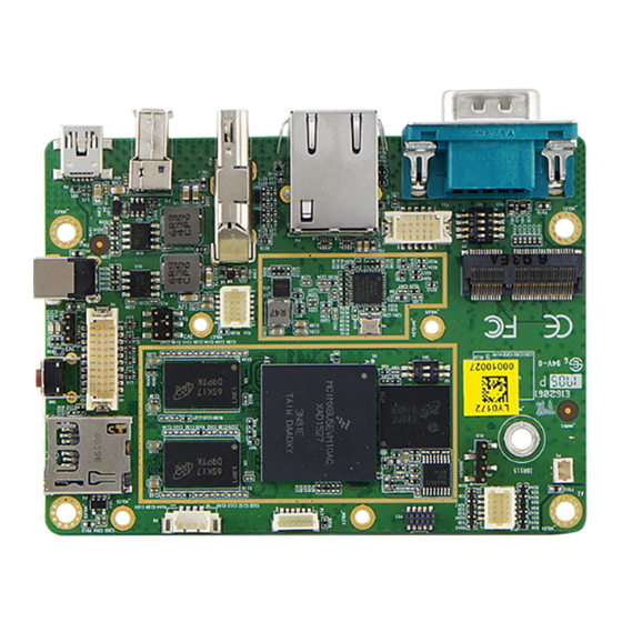
Page 20: Jumper & Connector Locations On Ibr115
Jumper & Connector Locations on IBR115 Board diagram of IBR115 IBR115 User’s Manual... -
Page 21: Jumpers Quick Reference
Hardware Configuration Jumpers Quick Reference Function Jumper Name Page LVDS Power Setting LVDS Backlight Power Setting 2.4.1 LVDS Power Setting (P16) Function Pin closed Illustration 3.3V (default) IBR115 User’s Manual... -
Page 22: Lvds Backlight Power Setting (P15)
2.4.2 LVDS Backlight Power Setting (P15) Function Pin closed Illustration 3.3V (default) IBR115 User’s Manual... -
Page 23: Connectors Quick Reference
2-Wire UART Connector Digital (GPIO) Connector C Connector System Reset Button DC Jack MicroSD Card Connector GbE LAN Port USB 2.0 Type A Port Mini-USB OTG Port NGFF M.2 Slot HDMI Port Factory Use Only SW1, P11, P19 IBR115 User’s Manual... -
Page 24: Rs-232/422/485 Selection (Sw3)
RS-422 Full Duplex Pure RS232 (3T/5R) RS-485 Half Duplex (TX Low-Active) RS-485 Half Duplex (TX High-Active) RS-422 Full Duplex Pure RS232 (1T/1R) RS-485 Half Duplex Shutdown (Default) 2.5.2 RTC Lithium Cell Connector (P2) Assigment Assigment RTC_VCC Ground IBR115 User’s Manual... -
Page 25: Lvds Display Connector (P8)
Hardware Configuration 2.5.3 LVDS Display Connector (P8) Assigment Assigment LCD1_TX0_P LCD1_TX0_N Ground Ground LCD1_TX1_P LCD1_TX1_N Ground LCD_VDD LCD1_TX3_P LCD1_TX3_N LCD1_TX2_P LCD1_TX2_N Ground Ground LCD1_CLK_P LCD1_CLK_N BTL_PWM LCD_VDD BKLT_VCC BKLT_VCC IBR115 User’s Manual... -
Page 26: Lvds Backlight Control Connector (P9)
2.5.4 LVDS Backlight Control Connector (P9) Assigment Assigment BKLT_VCC LCD_BKLT_PWM LCD_BKLT_EN Ground 2.5.5 USB Hub Connector (P13) Assigment Assigment Ground USB1_DP USB2_POWER USB1_DM USB2_DM USB1_POWER USB2_DP Ground IBR115 User’s Manual... -
Page 27: Com Rs-232/422/485 Port (P10)
Assigment DCD, Data carrier detect DSR, Data set ready RXD, Receive data RTS, Request to send TXD, Transmit data CTS, Clear to send DTR, Data terminal ready Ground Assignment RS-232 RS-422 RS-485 DATA- DATA+ Ground Ground Ground IBR115 User’s Manual... -
Page 28: Audio Connector (P14)
2.5.7 Audio Connector (P14) Assigment Assigment Ground LINE_IN_R Ground LINE_IN_L Ground Ground LINE_OUT_L Ground LINE_OUT_R 2.5.8 2-Wire UART Connector (P17) Assigment Assigment UART2_TXD UART3_TXD UART2_RXD UART3_RXD Ground Ground IBR115 User’s Manual... -
Page 29: Digital (Gpio) Connector (P18)
Hardware Configuration 2.5.9 Digital (GPIO) Connector (P18) Assigment Assigment 3.3V DIO5 DIO1 DIO6 DIO2 DIO7 DIO3 DIO8 DIO4 Ground 2.5.10 COM RS-232 Debug Connector (P19) Assigment Assigment RX, Receive data Ground TX, Transmit data IBR115 User’s Manual... -
Page 30: I 2 C Connector (P20)
2.5.11 C Connector (P20) Assigment Assigment I2C_SCL TP_INT_B I2C_SDA TP_RST_B IBR115 User’s Manual... -
Page 31: Chapter 3 Software Setup
Chapter 3 Software Setup This chapter introduces installation of the following drivers: • Make a recovery microSD card (for advanced users only) • Display parameter setting in kernel... -
Page 32: Make A Recovery Microsd Card
Make a Recovery MicroSD Card Note: This is for advanced users who has IBASE standard image file only. Basically, IBR115 is preloaded with O.S (Android / Linux) into eMMC by default. Connect the TFT-LCD with IBR115 (or HDMI), and 12V power directly. - Page 33 22 19530752 sdb6 32 976762584 sdc 3880960 sdd 512000 sdd1 3367936 sdd2 6-D. Compare 6-A and 6-C, and get sdd. Run make_card script. ./make_emmc_sd.sh /dev/sdd 20150814-111827 See "file system create done" mean success. Pull out the microSD card. IBR115 User’s Manual...
-
Page 34: Upgrade Firmware Through The Recovery Microsd Card
3.1.2 Upgrade Firmware through the Recovery MicroSD Card Insert the microSD card into IBR115. Insert power to boot up and microSD card upgrade. It takes about 15 minutes. After 10 minutes, the screen goes into sleep. When the upgrade is finished, the screen will automatically open. Do not power off. -
Page 35: Display Parameter Setting In Kernel
Power down and pull out microSD. Display Parameter Setting in Kernel IBR115 supports LVDS 15” output by default. If you use HDMI to display, run the command /home/root/display_config/config_displag_mode.sh 1 If you use LVDS 7” to display, run the command /home/root/display_config/config_displag_mode.sh 2... -
Page 36: Chapter 4 Bsp Source Guide
Chapter 4 BSP Source Guide This chapter is dedicated for advanced software engineers only to build BSP source. The topics covered in this chapter are as follows: • Preparation • Installing Toolchain • Building U-Boot • Building Kernel • Building RAMdisk Image (Optional) •... -
Page 37: 4.1 Building Bsp Source
Decompress the IBR115 source file ibr115.tar.xz into "/home/" folder. 4.1.2 Installing Toolchain Decompress Toolchain poky.tar into directory "/opt". 4.1.3... -
Page 38: Building Ramdisk Image (Optional)
Connect LVDS 15” display panel. Power on and you will see U-Boot prompt. If you want to change to another monitor (or display panel) type, refer to the section 3.2 Display Parameter Setting in Kernel to set video output command. IBR115 User’s Manual... -
Page 39: Appendix
Appendix This section provides the information of reference code. -
Page 40: How To Use Gpio In Linux
//open watchdog device fd = open("/dev/watchdog", O_WRONLY); //get watchdog support ioctl(fd, WDIOC_GETSUPPORT, &ident); //get watchdog status ioctl(fd, WDIOC_GETSTATUS, &status); //get watchdog timeout ioctl(fd, WDIOC_GETTIMEOUT, &timeout_val); //set watchdog timeout ioctl(fd, WDIOC_SETTIMEOUT, &timeout_val); //feed dog ioctl(fd, WDIOC_KEEPALIVE, &dummy); IBR115 User’s Manual... -
Page 41: Emmc Test
#read data2, and compare with data1 cmp $MOUNT_POINT_STR/data2 /tmp/data1 • eMMC speed test MOUNT_POINT_STR="/var" #get emmc write speed" time dd if=/dev/urandom of=$MOUNT_POINT_STR/test bs=1024k count=10 # clean caches echo 3 > /proc/sys/vm/drop_caches #get emmc read speed" time dd if=$MOUNT_POINT_STR/test of=/dev/null bs=1024k count=10 IBR115 User’s Manual... -
Page 42: Usb (Flash Disk) Test
USB (flash disk) Test Insert the USB flash disk then assure it is in IBR115 device list. Note: This operation may damage the data stored in the USB flash disk. Before starting the test, make sure there is no critical data in the eMMC flash being used. -
Page 43: Microsd Card Test
Appendix MicroSD Card Test When IBR115 is booted from eMMC, microSD card is “/dev/mmcblk1” and able to see by “ls /dev/mmcblk1*” command: /dev/mmcblk1 /dev/mmcblk1p2 /dev/mmcblk1p4 /dev/mmcblk1p5 /dev/mmcblk1p6 When booting from microSD card, replace test pattern “/dev/mmcblk1” to “/dev/mmcblk0”. Note: This operation may damage the data stored the microSD card. Before starting the test, make sure there is no critical data in the eMMC flash being used. -
Page 44: Rs-232 Test
&= ~CSIZE; options.c_lflag &= ~(ICANON | ECHO | ECHOE | ISIG); /*Input*/ options.c_oflag &= ~OPOST; /*Output*/ //options.c_cc options.c_cc[VTIME] = 150; options.c_cc[VMIN] = 0; #set parity tcsetattr(fd, TCSANOW, &options) //write ttymxc1 write(fd, write_buf, sizeof(write_buf)); //read ttymxc1 read(fd, read_buf, sizeof(read_buf))) IBR115 User’s Manual... -
Page 45: Rs-485 Test
TCSANOW, &options) //write ttymxc1 write(fd, write_buf, sizeof(write_buf)); //read ttymxc1 read(fd, read_buf, sizeof(read_buf))) Audio Test // play mp3 by audio (ALC5640) gplay-1.0 /home/root/ testscript/audio/a.mp3 -D plughw:1,0 // record mp3 by audio (ALC5640) arecord -f cd $basepath/b.mp3 -D plughw:1,0 IBR115 User’s Manual... -
Page 46: I 2 C Test
/home/root/testscript/ethernet/lftp_library/* /lib/ #lftp server 192.168.1.123 lftp 192.168.1.123 <<EOF #upload data to server 192.168.1.123 put data1 #download data from server 192.168.1.123 get data1 #exit lftp • Ethernet Ping test #ping server 192.168.1.123 ping -c 20 192.168.1.123 >/tmp/ethernet_ping.txt IBR115 User’s Manual... -
Page 47: Lvds Test
= 0; location = (x+g_xoffset) * (g_bits_per_pixel/8) + (y+g_yoffset) * g_line_length; *(fbp + location + 0) = color_b; *(fbp + location + 1) = color_g; *(fbp + location + 2) = color_r; //close framebuffer fd close(framebuffer_fd); IBR115 User’s Manual... -
Page 48: Hdmi Test
*(fbp + location + 1) = color_g; *(fbp + location + 2) = color_r; //close framebuffer fd close(framebuffer_fd); • HDMI audio test #enable hdmi audio echo 0 > /sys/class/graphics/fb2/blank #play wav file by hdmi audio aplay /home/root/testscript/hdmi/1K.wav -D plughw:0,0 IBR115 User’s Manual...
Need help?
Do you have a question about the IBR115 and is the answer not in the manual?
Questions and answers