Table of Contents
Advertisement
Advertisement
Table of Contents

Related Manuals for VAC V200P


Summary of Contents for VAC V200P
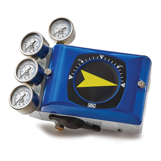
- Page 1 V200 POSITIONER www.vacaccessories.com 92026r15...
-
Page 3: Table Of Contents
V200 POSITIONER www.vacaccessories.com CONTENTS 1 INTRODUCTION .................. 4 Principle of Operation .............. 4 1.2 Product Identification ............... 4 Air quality recommendations ........... 5 Safety Instructions ..............5 2 INSTALLATION ..................6 Connections ................6 General mounting instructions ..........7 2.2.1 Rotary actuators ..............7 2.2.2 Linear actuators .............. -
Page 4: Introduction
V200 POSITIONER www.vac.se 1 INTRODUCTION 1.1 Principle of Operation arm and follows the balance arm’s movement. The V200 incorporates the force balance The system is stable when the gold plated principal of operation. The desired value, in the form of pressure, affects the membrane(1) spool(7) is in the neutral position and the forces that affect the balance arm is in equilibrium. -
Page 5: Air Quality Recommendations
V200 POSITIONER www.vacaccessories.com 1.3 Air quality recommendations To ensure normal operational safety with VAC positioner products, we recommend that a wa- Poor air quality is one of the main causes of ter separator and a <80 micrometer filter are premature functional problems with pneumatic mounted as close to the product as possible. and electro pneumatic equipment. The pilot... -
Page 6: Installation
V200 POSITIONER www.vac.se 2. INSTALLATION 2.1 Connections S – Supply air V200P: max. 145 PSI / 1 MPa V200E: 23 - 145 PSI / 0,15 -1 MPa I – Input, pressure signal V200P: 3-15 PSI / 20-100 kPa V200E: Plugged – Input, current signal V200E: 4-20 mA (Ri max 250 ohm) V200P: Plugged C+ - Actuator connection + stroke C- - Actuator connection - stroke OUT - All air from the actuator, IP and posi- tioner is vented through this port. -
Page 7: General Mounting Instructions
The V200 has the ISO F05 hole pattern(1) and 2¼” x 2¼” hole pattern(2). depth depth 2.2.1 Rotary actuator The VAC V200 has a very stable and properly sized drive shaft bearing. However, the posi- tioner drive(A) should be aligned properly to the rotary actuator spindle(B). A relatively small error combined with a rigid coupling can create very powerful radial forces, which can overload and cause premature wear. -
Page 8: Installation Instructions For Rotary Actuators
V200 POSITIONER www.vac.se 2.3 Installation instructions for rotary actuators Direct (CCW) 2.3.1 Double acting Signal opens Reverse (CW) Signal closes 2.3.2 Single acting Direct (CCW) Reverse (CW) Spring closes Spring opens Signal closes Signal opens Direct (CCW) Reverse (CW) Spring opens... -
Page 9: Installation Instructions For Linear Actuators
V200 POSITIONER www.vacaccessories.com 2.4 Installation instructions for linear actuators 2.4.1 Double acting Direct (CCW) Signal closes Signal opens Reverse (CW) Signal opens Signal closes 2.4.2 Single acting Spring opens Spring closes Direct (CCW) Signal closes Signal opens Spring opens Spring closes Reverse (CW) Signal opens Signal closes... -
Page 10: Cam
V200 POSITIONER www.vac.se 2.5 Cam The V200 is standard shipped with the C1-cam, factory set for 90° , direct (CCW) turning. ±1° 2.5.1 Adjustments Remove the front cover and indicator. (see page 15) 1. Loosen the locking screw(2) and the cam nut(1). -
Page 11: Spindle(Drive)
V200 POSITIONER www.vacaccessories.com 2.6 Spindle (Drive) VAC offers a variety of spindles/drives(1), suitable for the most frequently used actuator types. 2.6.1 Spindle Removal Release the spindle/drive by prying with two screwdrivers, equally under the edges(2) of the spindle/drive, using the housing as fulcrum. The spindle has a snap ring that is “released” with the equal pressure. 2.6.2 Spindle Mounting Press the spindle down into the spindle shaft hole. -
Page 12: Installing Ip Converter
V200 POSITIONER www.vac.se 2.7 Installing IP converter 2.7.1 Internal IP Converter Remove the front cover and indicator. (see page 15) 1. Loosen the two screws that secure the pneumatic sealing plate(1) and remove the plate. 2. Make sure the two O-rings(2) are still in the positioner housing. -
Page 13: Ma Connection
V200 POSITIONER www.vacaccessories.com 2.8 4-20 mA connection 2.8.1 Connecting the control signal Remove the front cover and indicator. (see page 15) Terminal block(1) is now easily acces- sible. Connect the cables to their respective pole. Maximum cable size AWG 13 (2,5 mm 2.8.2 Checking the control signal The control signal can be checked without having to break the signal loop. -
Page 14: Calibration
V200 POSITIONER www.vac.se 2.9 Calibration The V200 is delivered factory calibrated 0-100 % ±1%. Calibration procedure Zero position Note: Always set zero first! 1. Set 0% input signal. 2. W ait until the valve/actuator has responded. 3. Adjust the zero position by turning the zero screw(1), with a screwdriver. -
Page 15: Front Cover And Indicator
V200 POSITIONER www.vacaccessories.com 2.10 Front cover and indicator 2.10.1 Removing the front cover Loosen the two screws(1) and remove the front cover. 2.10.2 Removing flat indicator cover With the main cover removed, the indicator cover(2) (clear cover) can be removed with pressure from the backside. -
Page 16: Installing Flat Indicator Cover
V200 POSITIONER www.vac.se 2.10.5 Installing flat indicator cover Place the indicator cover(1) facing down to- ward the front cover. Press in the center of the indicator cover until it snaps into place. 2.10.6 Installing Dome Indicator cover Place the dome indicator cover(2) so that it is aligned with its seat in the front cover on one side. -
Page 17: Main Supply Filter For Ip Converter
V200 POSITIONER www.vacaccessories.com 2.11 Main supply filter for IP converter Changing the filter 1. Turn off or disconnect the main air supply. Should air supply not be disconnected or turned off, the pressure may cause the filter cover to eject from the unit. 2. Loosen the screw(1) and remove filter cover(2) 3. Cautiously remove the filter(3) with a sharp pointed object e.g. a pocket knife. 4. Press the new filter(3) into the housing. 5. Check the O-ring(4) and replace if needed. -
Page 18: Pilot Valve Remove And Install
V200 POSITIONER www.vac.se 2.12 Pilot valve Removal Remove the front cover and indicator. (see p.15) Loosen the pilot retaining screw(1). Lift the pilot valve(2) straight up. Cleaning Remove the gold plated spool(3) from the valve housing Clean the parts with a soft cloth and pipe cleaner using alcohol, acetone or something similiar. -
Page 19: Intentionally Blank
V200 POSITIONER www.vacaccessories.com Intentionally blank 92026r15... -
Page 20: Spare Parts
V200 POSITIONER www.vac.se 3. SPARE PARTS 3.1 Exploded drawing 92026r15... -
Page 21: Spare Parts List
V200 POSITIONER www.vacaccessories.com 3.2 Spare parts list Item Description Material Part no Item Description Material Part no 1 ..Housing ........Aluminum, painted ..n/a ....1 23 ..Cover plate ......Aluminum, painted ..90080 ....1 ..- Bearing 15x8 ...............171508 .... 2 24 .. -
Page 22: Specifications
V200 POSITIONER www.vac.se 4. SPECIFICATIONS 4.1 Specifications V200 Pneumatic Electropneumatic Electropneumatic Intrinsically Safe V200P V200E V200IS nput Signal: 3-15 PSI 4-20mA (Max:Ri 250 Ohm) 4-20mA (Max:Ri 250 Ohm) Supply Pressure: <145 PSI (<1MPa) 21.8-145 PSI (0.15-1MPa) 21.8-145 PSI (0.15-1MPa) Linearity error: <0.7% f.s <1.0% f.s <1.0% f.s Hysteresis: <0.4% f.s <0.6% f.s <0.6% f.s Repeatability: <0.3% f.s <0.5% f.s <0.5% f.s Temperature range: -40° to +185 F -40° to +185 F... -
Page 23: Dimension
V200 POSITIONER www.vacaccessories.com 5. DIMENSIONS 5.1 V200P/E std 92026r15... - Page 24 V200 POSITIONER www.vac.se 92026r15...
Need help?
Do you have a question about the V200P and is the answer not in the manual?
Questions and answers