Advertisement
Table of Contents
Advertisement
Table of Contents

Related Manuals for Bell'O TPC2133


Summary of Contents for Bell'O TPC2133
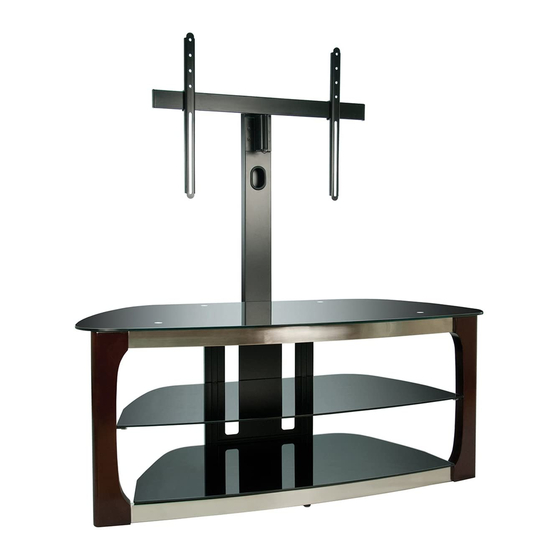
- Page 1 ASSEMBLY INSTRUCTIONS TPC2133 FLAT PANEL TV MOUNTING SYSTEM...
- Page 2 BELL’O INTERNATIONAL CORPORATION WILL NOT BE RESPONSIBLE FOR FAILURE TO ASSEMBLE AS DIRECTED OR FOR THE IMPROPER ASSEMBLY, USE, OR HANDLING OF THIS PRODUCT. ! IMPROPER INSTALLATION OF THIS PRODUCT MAY CAUSE DAMAGE OR SERIOUS INJURY. BELL'O INTERNATIONAL CORPORATION CANNOT BE LIABLE FOR DIRECT OR INDIRECT DAMAGE OR INJURY CAUSED BY INCORRECT MOUNTING, INCORRECT USE, OR INCORRECT ASSEMBLY.
- Page 3 65 mm 15 mm 30 mm...
- Page 4 27 mm TVM1 TVM7 4 x 15 mm 8 x 20 mm TVM2 TVM8 4 x 30 mm 8 x 40 mm Short Spacer TVM3 TVM9 5 x 15 mm Long Spacer TVM4 TVM10 5 x 30 mm Washer M4/M5 TVM11 TVM5 6 x 15 mm...
- Page 5 NOTE: 2 PEOPLE ARE RECOMMENDED TO ASSEMBLE THIS FURNITURE. TO AVOID DAMAGE DURING ASSEMBLY, IT SHOULD BE ASSEMBLED ON A SOFT SURFACE. Fig. 1-1 1-1. REMOVE the Frame Assembly (M1) from the packaging and UNFOLD as shown.
- Page 6 1-2. LOCK the Frame Assembly (M1) into an open position by engaging the Locking Mechanisms as shown. NOTE: IF YOU WILL BE USING THE TPC2133 WITH THE TV MOUNTING SYSTEM (OPTION 2), CONTINUE FOR FURTHER INSTRUCTIONS. IF YOU WILL BE USING THE WALL MOUNT FEATURE (OPTION 3), PLEASE SKIP TO PAGE 14.
- Page 7 Fig. 2-1 2-1. INSERT the bottom pegs of the Flat Panel Support Post (M2) into the holes at the BOTTOM rear of the CMS ® (Cable Management System) Panel (M1) and PUSH down. SECURE with two 65 mm Screw Knobs (M10) as shown in Fig. 2-1. 2-2.
- Page 8 2-3. SELECT THE CORRECT SCREW. Before beginning, test several of the Screws in your Hardware Kit to find the correct size and length for your television. NOTE (!): Use Spacers if Monitor Arms (M5) do not fit firmly against the back of the television, such as when the back of the television is curved, contains larger recessed mounting holes, or some other obstruction is in the way.
- Page 9 Fig. 2-3 2-4. SLIDE Monitor Arms (M5) on to the Swivel Bar (M4) and then INSERT the 30 mm Turn Knobs (M12) through the Monitor Arms as shown. DO NOT YET FULLY TIGHTEN THE KNOBS. 2-5. PLACE your TV face-down on a very soft, non-abrasive surface, taking extreme caution to not damage the face of your TV. 2-6.
- Page 10 Fig. 2-4 2-8. With the help of an assistant, carefully PLACE the Post of the Swivel Bar (M4) down into the tube in the Mounting Bracket (M3), and SECURE with the Post Locking Clip (M13) as shown. SKIP TO PAGE 20 FOR GLASS SHELF INSTALLATION INSTRUCTIONS.
- Page 11 Fig. 3-1 3-1 Using a stud finder, FIND the exact location of the studs to which you want to attach the Wall Mount (M9). MARK the right and left side to determine the center of each stud. [FIGURE 3-1]...
- Page 12 Fig. 3-2 3-2. MEASURE the distance from the mounting holes on the back of your television to the top and bottom edges of the television to determine the true center of the television once it will be mounted. Many television manufacturers do not place the mounting holes exactly centered in the television.
- Page 13 Fig. 3-3 2.5" (64 mm) 5/32" (4 mm) INSTALLING THE WALL MOUNT IN WOOD: 3-4. DRILL four holes 2.5" (64 mm) deep using a 5/32" (or 4 mm) size drill bit in the “A”, “B”, “C”, and “D” locations noted on the Installation Template.
- Page 14 Fig. 3-4 3" (76 mm) MOUNTING TO SOLID CONCRETE OR CINDER BLOCK: 3-4. Carefully DRILL four holes using a 5/16" (or 8mm) masonry drill bit in the “A”, “B”, “C”, and “D” locations noted on the Installation Template. NOTE: EACH HOLE SHOULD BE AT LEAST 3" (76 MM) DEEP. [FIGURE 3-4] IMPORTANT: DO NOT DRILL INTO MORTAR JOINTS! DRILL HOLES AT LEAST 1"...
- Page 15 Fig. 3-5 3-5. REMOVE the Installation Template. 3-6. If mounting into concrete, INSERT four TOGGLER brand Wall Anchors (M17) into ® the drilled holes. [FIGURE 3-7] 3-7. PLACE the Wall Plate (M9) over the holes and SCREW in the Lag Bolts (M18) about half way.
- Page 16 Fig. 3-8 3-8. ATTACH the Mounting Bracket (M3) to the Wall Plate (M9) with four 15 mm Bolts (M11). TIGHTEN FULLY. Fig. 3-9 3-9. With the help of an assistant, carefully PLACE the Post of the Swivel Bar (M4) down into the tube in the Mounting Bracket (M3), and SECURE with the Post Locking Clip (M13) as shown.
- Page 17 Fig. 4-1 4-1. ATTACH the Middle Shelf Rear Support Brackets (M19) to the front of the CMS ® Panel (M1) with small Screws (M20) as shown.
- Page 18 Fig. 4-2 4-2. Carefully INSTALL the Top Glass Shelf (M8) as shown above. Make sure the silver posts under the Top Glass Shelf are properly inserted into the holes in the Top Shelf Support Bar (M1). SECURE the Top Glass Shelf to the Support Bar using four 27 mm Turn Knobs (M16) as shown.
Need help?
Do you have a question about the TPC2133 and is the answer not in the manual?
Questions and answers