Jacobsen Super LF 1880 Parts & Maintenance Manual
Fairway mower
Hide thumbs
Also See for Super LF 1880:
- Parts & maintenance manual (148 pages) ,
- Dealer's manual (50 pages) ,
- Safety & operation manual (36 pages)
Table of Contents
Advertisement
Quick Links
Parts & Maintenance Manual
Manual de Peças e Manutenção
67923 – Kubota D1105-E, 2WD
67924 – Kubota D1105-E, 4WD
67938 – Kubota D1105-TE, 4WD
WARNING: If incorrectly used, this machine can cause severe injury. Those who
use and maintain this machine should be trained in its proper use, warned of its
dangers and should read the entire manual before attempting to set up, operate,
adjust or service the machine.
AVISO: Esta máquina pode causar ferimentos graves se for utilizada incorrectamente. A
pessoa responsável pela sua utilização e manutenção deve ser previamente instruída
para a sua utilização correcta, avisada sobre os perigos que ela pode causar e deve ler
todo o manual antes de tentar preparar, conduzir, afinar ou reparar a máquina.
PT
GB
RJ 100 022003
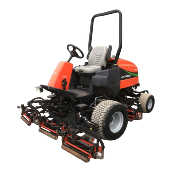
Super LF 1880™ Fairway Mower
Máquina de Cortar Grama Super LF 1880™ Fairway
4102143 (rev.A)-PT
Advertisement
Chapters
Table of Contents

Related Manuals for Jacobsen Super LF 1880


Summary of Contents for Jacobsen Super LF 1880
- Page 1 4102143 (rev.A)-PT Parts & Maintenance Manual Manual de Peças e Manutenção Super LF 1880™ Fairway Mower Máquina de Cortar Grama Super LF 1880™ Fairway 67923 – Kubota D1105-E, 2WD 67924 – Kubota D1105-E, 4WD 67938 – Kubota D1105-TE, 4WD WARNING: If incorrectly used, this machine can cause severe injury. Those who...
-
Page 2: Table Of Contents
To Order Parts 1. Write your full name and complete address on the 5. Send or bring the order to an authorized Textron Turf order. Care And Specialty Products Dealer. 2. Explain where and how to make shipment. 6. Inspect all shipments on receipt. If any parts are damaged or missing, file a claim with the carrier 3. -
Page 3: Service Parts
Suggested Stocking Guide To keep your equipment fully operational and productive, Textron Turf Care And Specialty Products suggests you maintain a stock of the more commonly used maintenance items. We have included part numbers for additional support materials and training aids. To order any of the following material: 3. -
Page 4: Safety
SAFETY SAFETY OPERATING SAFETY ______________________________________________________ WARNING EQUIPMENT OPERATED IMPROPERLY OR BY UNTRAINED PERSONNEL CAN BE DANGEROUS. Familiarize yourself with the location and proper use of all controls. Inexperienced operator’s should receive instruction from someone familiar with the equipment before being allowed to operate the machine. 1. -
Page 5: Important Safety Notes
SAFETY IMPORTANT SAFETY NOTES ________________________________________________ This safety alert symbol is used to alert you to potential hazards. DANGER - Indicates an imminently hazardous situation which, if not avoided, WILL result in death or serious injury. WARNING - Indicates a potentially hazardous situation which, if not avoided, COULD result in death or serious injury. -
Page 6: Specifications
PRODUCT IDENTIFICATION _________________________________________________ 67923 ......Super LF 1880 2WD. 67924 ......Super LF 1880 4WD. TEXTRON TURF CARE AND SPECIALTY PRODUCTS 67938 ......Super LF 1880 Turbo 4WD RACINE, WI MADE IN U.S.A. Serial Number ....An identification plate, like the one... -
Page 7: Cutting Units
SPECIFICATIONS CUTTING UNITS: __________________________________________________________ Reel......... 5 Reels, 18 in. (457 mm) wide. Cutting Width ....80 in. (2032 mm) Reel Diameter ....5 in. (127 mm) Cutting Frequency: Blade Options ....8 or 11 blades 8 Blade...... 0.067 in./mph (1.06 mm/kph) Cutting Height .... -
Page 8: Adjustments
ADJUSTMENTS ADJUSTMENTS GENERAL________________________________________________________________ adjustment cannot be made, contact an authorized WARNING Textron Golf, Turf & Specialty Products Dealer. 2. Replace, adjust, worn damaged To prevent injury, lower implements to the ground, components. disengage all drives, engage parking brake, stop engine and remove key from ignition switch before 3. -
Page 9: Neutral Switch And 4Wd Cut-Out Switch
ADJUSTMENTS NEUTRAL SWITCH AND 4WD CUT-OUT SWITCH _______________________________ The traction pedal is designed to return to neutral 2. Adjust switch (I) as required to position the sensing whenever the forward or reverse foot pedals are area under the return arm as shown with pump in relaesed. -
Page 10: Traction Pedal Speed Limiter
ADJUSTMENTS TRACTION PEDAL SPEED LIMITER __________________________________________ Cutting quality is better at speeds well below the Transport Position Mow Position transport speed of the tractor. An initial mow speed of 6 mph is set at the factory and should be satisfactory for most cutting conditions. -
Page 11: Steering Adjustments
ADJUSTMENTS STEERING ADJUSTMENTS__________________________________________________ 1. Turn wheels to straight ahead position. 2. Loosen jam nuts (Q) on both sides of tie rod (R). 3. Turn tie rod (R) to provide proper toe-in. Toe-in must not exceed +1/16” (1.5 mm) (S). Align ball joints and tighten jam nuts. -
Page 12: Bedknife-To-Reel
ADJUSTMENTS 3.11 BEDKNIFE-TO-REEL _______________________________________________________ (Pre-adjustment Check) Check the reel bearings for end play or radial play. The reel must be parallel to the bedknife. An There should be no end play or radial play. See Section improperly adjusted reel will lose its sharp edges 3.14. -
Page 13: Cutting Height
ADJUSTMENTS 3.13 CUTTING HEIGHT _________________________________________________________ Note: Always make the reel to bedknife adjustment 6. Repeat Steps 4 and 5 on opposite end. Complete before adjusting height of cut. (Sections 3.11 and 3.12). adjustment to one end before adjusting opposite end. 7. -
Page 14: Flash Attach
ADJUSTMENTS 3.15 FLASH ATTACH___________________________________________________________ Installing Cutting units Remove cap (M) on lift arm. Unfasten retaining clip (L) from pin (K) and remove pin. Place each cutting unit in front of its respective lift arm. Raise lift arm and position cutting unit so that yoke (R) is Carefully raise arm until cutting unit can be removed. -
Page 15: Torque Specification
ADJUSTMENTS 3.17 TORQUE SPECIFICATION ___________________________________________________ CAUTION All torque values included in these charts are approximate and are for reference only. Use of these torque values is at your sole risk. Textron Golf, Turf & Specialty Products is not responsible for any loss, claim, or damage arising from the use of these charts. -
Page 16: Maintenance
MAINTENANCE MAINTENANCE GENERAL________________________________________________________________ Keep all moving parts properly adjusted and lubri- WARNING cated. Replace worn or damaged parts before operating Before you clean, adjust, or repair this equipment, the machine. disengage all drives, lower implements to the ground, engage parking brake, stop engine and remove key from Keep all fluids at their proper levels. -
Page 17: Air Filter
MAINTENANCE AIR FILTER _______________________________________________________________ Check the service indicator daily. If red band appears in the Check all hoses and air ducts. Tighten hose clamps. window (C) replace the element. Do not remove the element for inspection or cleaning. Unnecessary removal of the filter increases the risk of injecting dust and other impurities into the engine. -
Page 18: Battery
MAINTENANCE BATTERY ________________________________________________________________ Make absolutely certain the ignition switch is “Off” and the When installing the battery, always assemble the RED, positive (+) battery cable first and the ground, BLACK, key has been removed before servicing the battery. negative (-) cable last. CAUTION When removing the battery, always remove the ground, BLACK, negative (-) cable first and the RED,... -
Page 19: Hydraulic Hoses
MAINTENANCE 4.10 HYDRAULIC HOSES _______________________________________________________ IMPORTANT: hydraulic system WARNING permanently damaged becomes contaminated. Before disconnecting any hydraulic To prevent serious injury from hot, high pressure oil, component, clean the area around the fittings and the never use your hands to check for oil leaks, use paper or hose ends to keep impurities out of the system. -
Page 20: Electrical System
MAINTENANCE Figure 4B 4.12 ELECTRICAL SYSTEM _____________________________________________________ CAUTION Fuses F1 5 Amp (Gauges) F2 20 Amp (Lights) F3 10 Amp (Lift / Lower) Always turn the ignition switch off and remove the F4 Not Used F1 F2 F3 F4 F5 30 Amp (Glow Plugs) negative battery cable (Black) before inspecting or F6 10 Amp (Ignition Switch) F7 20 Amp (Ignition Circuit) -
Page 21: Muffler And Exhaust
MAINTENANCE 4.13 MUFFLER AND EXHAUST ___________________________________________________ To protect from carbon monoxide poisoning, inspect the WARNING complete exhaust system regularly and always replace a defective muffler. Exhaust fumes contain carbon monoxide that is toxic and can be fatal when inhaled. If you notice a change in the color or sound of the exhaust, stop the engine immediately. -
Page 22: Care And Cleaning
MAINTENANCE 4.17 CARE AND CLEANING _____________________________________________________ Wash the tractor and implements after each use. Keep the Clean all plastic or rubber trim with a mild soap equipment clean. solution or use commercially available vinyl/rubber cleaners. Note: Do not wash any portion of the equipment while it is Repair damaged metal surfaces and use Textron Golf, Turf hot. -
Page 23: Backlapping
MAINTENANCE 4.19 BACKLAPPING____________________________________________________________ 4. Adjust the reel valves located under the operator WARNING platform, to the desired speed. 5. Apply lapping compound with a long handle brush to To prevent injury, keep hands, feet and clothing away high spots first then along entire length of the reel. from rotating reels. -
Page 24: Storage
MAINTENANCE 4.20 STORAGE________________________________________________________________ General 4. If storing indoors, drain fuel from tank. 5. Close fuel shut off valve. Wash the tractor thoroughly and lubricate. Repair and paint damaged or exposed metal. Cutting Units Inspect the tractor, tighten all hardware, replace worn Wash the cutting units thoroughly, then repair and paint or damaged components. -
Page 25: Troubleshooting
TROUBLESHOOTING TROUBLESHOOTING GENERAL TROUBLESHOOTING _____________________________________________ The troubleshooting chart below lists basic problems that may occur during start-up and operation. For more detailed information regarding the hydraulic and electrical systems contact your area Textron Golf, Turf & Specialty Products Dealer. Symptoms Possible Causes Action Engine will not start. -
Page 26: Maintenance & Lubrication Charts
MAINTENANCE & LUBRICATION CHARTS MAINTENANCE & LUBRICATION CHARTS GENERAL________________________________________________________________ 2. Lubricate with grease that meets or exceeds NLGI WARNING Grade 2 LB specifications. Apply grease with a manual grease gun and fill slowly until grease begins Before you clean, adjust, or repair this equipment, to seep out. -
Page 27: Maintenance Charts
MAINTENANCE & LUBRICATION CHARTS MAINTENANCE CHARTS ___________________________________________________ Recommended Service and Lubrication Intervals Every Every Every Every Every Every Every Yearly Lubricant 8-10 1000 Section Type Hours Hours Hours Hours Hours Hours Hours Air Filter Battery Charge Belts I-A* Brake I-A* Cooling System I-C-A 4.18... - Page 28 NOTES NOTES GB-28...
-
Page 29: Notes Parts Catalog Table Of Contents
NOTES GB-29... - Page 30 Para Fazer Pedido de Peças 1. Preencha seu nome e endereço completos no pedido. 5. Envie ou leve o pedido até um revendedor autorizado Textron Golf, Turf & Specialty Products. 2. Explique onde e como fazer a remessa. 6. Inspecione todos os itens da remessa ao recebê-los. Se 3.
- Page 31 Sugestão para stock de peças Para manter o seu equipamento inteiramente operacional e a dar bom rendimento, a Textron Golf, Turf & Specialty sugere a manutenção de um stock com os materiais de manutenção mais vulgarmente usados. Incluímos Products números de peças para materiais adicionais de apoio e ajudas para treino. Para encomendar qualquer do material seguinte: 1.
-
Page 32: Segurança
SEGURANÇA SEGURANÇA SEGURANÇA NO FUNCIONAMENTO _________________________________________ ATENÇÃO O EQUIPAMENTO UTILIZADO INADEQUADAMENTO OU POR PESSOAL NÃO TREINADO PODE SER PERIGOSO Familiarize-se com a localização e com a utilização correcta de todos os comandos. Condutores sem experiência devem receber formação de alguém que já conheça o equipamento antes de serem autorizados a conduzir a máquina. -
Page 33: Importantes Instruções De Segurança
SEGURANÇA IMPORTANTES INSTRUÇÕES DE SEGURANÇA ________________________________ Esta chamada de atenção de segurança é usado para assinalar perigos potenciais. PERIGO - Indica uma situação de perigo iminente que, se não for evitada, PROVOCARÁ a morte ou ferimentos graves. ATENÇÃO - Indica uma situação potencialmente perigosa que, se não for evitada, PODE provocar a morte ou ferimentos graves. -
Page 34: Especificações
IDENTIFICAÇÃO DO PRODUTO ______________________________________________ 67923 ......Super LF 1880 2WD 67924 ......Super LF 1880 4WD TEXTRON TURF CARE AND SPECIALTY PRODUCTS 67938 ......Super LF 1880 Turbo 4WD RACINE, WI MADE IN U.S.A. Número de Série .... Uma chapa de identificação como... -
Page 35: Unidades De Corte
ESPECIFICAÇÕES UNIDADES DE CORTE______________________________________________________ Rolo de lâminas ....5 Rolos de lâminas, 457 mm de Altura de Corte....7,6 a 18 mm largura Largura de Corte..... 2032 mm Diâmetro do rolo Frequência de Corte: de lâminas....... 127 mm 8 Lâminas ....1,06 mm/km/h Opções de Lâminas .. -
Page 36: Afinações Considerações Gerais
AFINAÇÕES AFINAÇÕES CONSIDERAÇÕES GERAIS _________________________________________________ Afinações e trabalhos de manutenção devem ser sem- ATENÇÃO pre executados por técnicos qualificados. Se a afinação apropriada não puder ser realizada, entre em contacto Para evitar lesões, baixe os utensílios até ao solo, com o distribuidor autorizado da Textron Golf, Turf & desengate todos os accionadores, puxe o travão de Specialty Products. -
Page 37: Interruptor Neutro E Interruptor De Corte De 4Wd
AFINAÇÕES INTERRUPTOR NEUTRO E INTERRUPTOR DE CORTE DE 4 WD ___________________ O pedal de tracção regressa à posição neutra quando os Ajuste o interruptor (I) para colocar a área sensora sob pedais de avanço ou recuo são soltos. Se o trator continuar o braço de retorno como se indica com a bomba na a avançar lentamente depois do pedal de tração ser solto, posição neutra. -
Page 38: Limitador De Velocidade Do Pedal De Tração
AFINAÇÕES LIMITADOR DE VELOCIDADE DO PEDAL DE TRAÇÃO __________________________ A qualidade do corte melhora a velocidade muito inferior à Posição de transporte Posição de corte Transport Position Mow Position de transporte do trator. De fábrica vem ajustada a velocidade de corte inicial de 10 km/h, que deve ser suficiente para a maior parte das condições. -
Page 39: Ajustes Da Direção
AFINAÇÕES AJUSTES DA DIREÇÃO_____________________________________________________ Endireite as rodas. Solte as porcas (Q) em ambos os lados do tirante (R). Rode o tirante (R) para a convergência correta das rodas. A convergência não pode exceder 1,5 mm (S). Alinhe as juntas esféricas e aperte as porcas. Após o ajuste do tirante, ajuste o cilindro da direção rodando a junta esférica (T) para que o braço do fuso fique à... -
Page 40: Lâmina Fixa Para Rolo De Lâminas
AFINAÇÕES 3.11 LÂMINA FIXA PARA ROLO DE LÂMINAS ______________________________________ (Verificação de pré-afinação) Verifique os mancais do rolo em relação a folga na O rolo deve estar paralelo à lâmina fixa. Um rolo inadequadamente ajustado perderá prematuramente a extremidade ou a folga radial. Não deve haver folga afiação das bordas e poderá... -
Page 41: Altura Do Corte
AFINAÇÕES 3.13 ALTURA DO CORTE________________________________________________________ Nota: Faça sempre a afinação do rolo de lâminas para a Repita os passos 4 e 5 no lado oposto. Conclua a lâmina fixa antes de ajustar a altura do corte (pontos 3.11 e afinação para uma extremidade antes de afinar o lado 3.12). -
Page 42: Flash Attach
AFINAÇÕES 3.15 FLASH ATTACH___________________________________________________________ Coloque cuidadosamente o motor com a tubagem Instalação das unidades de corte longe da unidade de corte. Para evitar contaminação e Coloque cada unidade de corte à frente do respectivo danos aos componentes internos, tape a cavidade do braço de subida. -
Page 43: Binário
AFINAÇÕES 3.17 BINÁRIO _________________________________________________________________ CUIDADO Todos os valores de binário incluídos nestas tabelas são aproximados e servem apenas como referência. A aplicação destes valores de binário é por conta e risco do utilizador. A Textron Golf, Turf & Specialty Products não se responsabiliza por quaisquer perdas, reclamações ou danos resultantes da aplicação destas tabelas. -
Page 44: Manutenção
MANUTENÇÃO MANUTENÇÃO CONSIDERAÇÕES GERAIS _________________________________________________ Mantenha o equipamento limpo. ATENÇÃO Mantenha todos os componentes móveis correcta- mente afinados e lubrificados. Antes de proceder a limpeza, afinações ou reparações neste equipamento, desengate todos os accionadores, Substitua peças gastas ou danificadas antes de baixe os utensílios até... -
Page 45: Filtro De Ar
MANUTENÇÃO FILTRO DE AR ____________________________________________________________ Verifique o indicador de serviço diariamente. Se a faixa Recoloque a tampa certificando-se de que ela fica vermelha aparecer na abertura (C), substitua o elemento. completamente vedada em torno da carcaça do filtro. O evacuador de poeiras deve estar virado para baixo. Não remova o elemento para inspecção ou limpeza. -
Page 46: Bateria
MANUTENÇÃO BATERIA_________________________________________________________________ Certifique-se de forma absoluta de que o interruptor de Verifique a polaridade da bateria antes de ligar ou desligar ignição está “desligado” e de que a chave foi retirada antes os cabos da bateria. de realizar qualquer serviço na bateria. Ao instalar a bateria, monte sempre primeiro o cabo de bateria VERMELHO, positivo (+), e, por último, o cabo CUIDADO... -
Page 47: Mangueiras Hidráulicas
MANUTENÇÃO 4.10 MANGUEIRAS HIDRÁULICAS________________________________________________ IMPORTANTE: sistema hidráulico pode ATENÇÃO permanentemente danificado óleo ficar contaminado. Antes de desligar qualquer componente hidráulico, limpe a área em torno dos encaixes e das Para evitar lesões graves provocadas por óleo quente a extremidades das mangueiras para que impurezas não alta pressão, nunca use as mãos para verificar fugas de penetrem no sistema. -
Page 48: Sistema Eléctrico
MANUTENÇÃO 4.12 SISTEMA ELÉCTRICO______________________________________________________ CUIDADO Fusíveis F1 5 Amp (Indicadores) F2 20 Amp (Lâmpadas) F3 10 Amp (Subir / Descer) F4 Não utilizado Desligue sempre o interruptor de ignição e remova o F1 F2 F3 F4 F5 30 Amp (Velas de incandescência) cabo negativo da bateria (preto) antes de inspeccionar F6 10 Amp (Interruptor de ignição) F7 20 Amp (Circuito de ignição) -
Page 49: Silenciador E Escape
MANUTENÇÃO 4.13 SILENCIADOR E ESCAPE ___________________________________________________ Para se proteger contra envenenamento por monóxido de ATENÇÃO carbono, inspeccione regularmente o sistema de escape completo e substitua sempre um silenciador danificado. O fumo do escape contém monóxido de carbono que é Se observar uma mudança de cor ou de som no escape, tóxico e pode ser fatal quando inalado. -
Page 50: Cuidados E Limpeza
MANUTENÇÃO 4.17 CUIDADOS E LIMPEZA _____________________________________________________ Lave o tractor e os utensílios após cada utilização. Limpe todo o acabamento de plástico ou borracha com Mantenha o equipamento limpo. uma solução fraca de sabão ou utilize detergentes para vinil/borracha disponíveis em estabelecimentos Nota: Não lave qualquer parte do equipamento enquanto comerciais. -
Page 51: Inversão Do Sentido De Rotação Dos Rolos
MANUTENÇÃO 4.19 INVERSÃO DO SENTIDO DE ROTAÇÃO DOS ROLOS ____________________________ Ajuste na velocidade pretendida as válvulas do rolo de ATENÇÃO lâminas localizadas sob a plataforma do operador. Aplique produto de polir com uma escova de cabo Para evitar ferimentos graves, mantenha as mãos, os comprido em primeiro lugar em locais altos e pés e o vestuário longe de peças em rotação. -
Page 52: Armazenamento
MANUTENÇÃO 4.20 ARMAZENAMENTO ________________________________________________________ Considerações Gerais Se guardar em local fechado, retire o combustível do reservatório. Lave completamente o tractor e lubrifique-o. Repare e Feche a válvula de corte de combustível. pinte partes de metal danificadas ou expostas. Unidades de Corte Inspeccione o tractor, aperte todas as ferragens, substitua componentes gastos ou danificados. -
Page 53: Reparação De Avarias
REPARAÇÃO DE AVARIAS REPARAÇÃO DE AVARIAS CONSIDERAÇÕES GERAIS _________________________________________________ A tabela de resolução de problemas apresentada a seguir indica os problemas básicos que podem ocorrer no início e durante o funcionamento. Para obter informações mais detalhadas em relação aos sistemas hidráulico e eléctrico, entre em contacto com o distribuidor Textron Golf, Turf &... -
Page 54: Tabelas De Manutençãoe Lubrificação
TABELAS DE MANUTENÇÃO E LUBRIFICAÇÃO TABELAS DE MANUT ENÇÃO E LUBRIFICAÇÃO CONSIDERAÇÕES GERAIS _________________________________________________ Lubrifique com massa que equivalha ou exceda as ATENÇÃO especificações da classificação NLGI 2LB. Aplique massa com uma almotolia e encha lentamente até que Antes de limpar, ajustar ou reparar este equipamento, a massa comece a extravasar. -
Page 55: Tabela De Manutenção
TABELAS DE MANUTENÇÃO E LUBRIFICAÇÃO TABELA DE MANUTENÇÃO _________________________________________________ Periodicidade recomendada para assistência e lubrificação A cada A cada A cada A cada A cada A cada A cada Anual- Tipo de 8-10 1000 mente Secção lubrifi- horas horas horas horas horas horas... - Page 56 NOTAS NOTAS PT-28...
- Page 57 NOTAS PT-29...
- Page 58 LF 1880 Serial No. All 1.1 Decals OPERATING INSTRUCTIONS READ MANUAL THOROUGHLY FOR OPERATING AND SAFETY INSTRUCTIONS. REPLACEMENT MANUAL AVAILABLE FROM: JACOBSEN/TEXTRON, RACINE WI. TO START TO DRIVE TO USE IMPLEMENT TO STOP 1. Set Parking Brake. 1. Release parking 1.
- Page 59 Decal, Warning 3008521 Decal, Traction Pedal 3008003 Decal, Instruction 3008930 Decal, Flash Attach 4117791 Pad, Step 4118842 Decal, Super LF 1880 3006516 Pad, L.H. Platform 3006517 Pad, R.H. Platform 3006515 Pad, Center Platform 3006512 Pad, Center Floorboard 3006513 Pad, L.H. Floorboard 3006514 Pad, R.H.
- Page 60 LF 1880 Serial No. All 2.2 Decals Units with Green Stripe OPERATING INSTRUCTIONS READ MANUAL THOROUGHLY FOR OPERATING AND SAFETY INSTRUCTIONS. REPLACEMENT MANUAL AVAILABLE FROM: JACOBSEN/TEXTRON, RACINE WI. TO START TO DRIVE TO USE IMPLEMENT TO STOP 1. Set Parking Brake.
- Page 61 3008521 Decal, Traction Pedal 3008003 Decal, Instruction 4124720 Decal, Flash Attach 4117791 Pad, Step 4118842 Decal, Super LF 1880 4WD Remove 4WD Portion for 2WD Units 3006516 Pad, L.H. Platform 3006517 Pad, R.H. Platform 3006515 Pad, Center Platform 3006512 Pad, Center Floorboard 3006513 Pad, L.H.
- Page 62 LF 1880 Serial No. All 3.1 Body Components...
- Page 63 LF 1880 Item Part No. Qty. Description Serial Numbers/Notes 3005638 Floorboard 409812 Screw, 5/16-18 x 3/4” Thread Cut 403770 Screw, 5/16-18 x 3/4” Hex Flange 445781 Nut, 5/16-18 Whiz-Lock 3005650 Seat Pan 3007798 Lock Pin 1004943 Hood Assembly Includes Blue Stripe Decals >...
- Page 64 LF 1880 Serial No. All 4.1 Seat and Suspension...
- Page 65 LF 1880 Item Part No. Qty. Description Serial Numbers/Notes 66170 Suspension, Mini 5002620 • Spring Kit 400186 • Screw, 5/16-18 x 7/8” Hex Head 446136 • Lockwasher, 5/16 Heavy 443106 • Nut, 5/16-18 Hex 554718 • Nut, Push 554717 • Shaft, Pivot 554715 •...
- Page 66 LF 1880 Serial No. All 5.1 Instrument Panel...
- Page 67 LF 1880 Item Part No. Qty. Description Serial Numbers/Notes 1002677 Throttle Handle 1002858 Throttle Cable 1004290 Joystick, 1 Axis REFERENCE SW12, See 52.1 162720 Temperature Gauge REFERENCE U4, See 52.1 447002 • Lockwasher, #6 External Tooth 444304 • Nut, #6-32 447206 •...
- Page 68 LF 1880 Serial No. All 6.1 Traction Pedal and Linkage...
- Page 69 LF 1880 Item Part No. Qty. Description Serial Numbers/Notes 2810214 Arm, Neutral Return 461383 Roll Pin, 3/16 x 1” 2809632 Bracket, Neutral Return 4121563 Rod, Neutral Return 2809634 Spring, Compression 2809635 Spacer 2809856 Guide, Spring 452008 Flat Washer, 3/8 3005971 Spacer 366974 Rod End, 3/8-24...
- Page 70 LF 1880 Serial No. All 7.1 Parking Brake N / S N / S N / S...
- Page 71 LF 1880 Item Part No. Qty. Description Serial Numbers/Notes 1003872 Pedal, Brake 2811143 Brake Caliper, Left Side 2811144 Brake Caliper, Right Side 503660 • Replacement Pad Set 557823 • Pivot Pin 557824 • Pad, Support 557825 • Spring, Lever Retainer 557826 •...
- Page 72 LF 1880 Serial No. All 8.1 Frame and Front Axle...
- Page 73 LF 1880 Item Part No. Qty. Description Serial Numbers/Notes 1003536 Channel, Bumper 5003218 Motor, Front Wheel See 43.1 554780 • Key 554779 • Nut 1004245 Mount, Bumper 2809907 Nut, M10 Spiralock Flange 2811692 Frame 453011 Flat Washer, 3/8 Wheel and Tire Assembly 4108620 •...
- Page 74 LF 1880 Serial No. All 9.1 Steering Tower...
- Page 75 LF 1880 Item Part No. Qty. Description Serial Numbers/Notes 5002918 Actuator, Gas Spring 5002919 Cable, Actuator 2811346 Tower, Steering 4101283 Valve, Steering See 45.1 443828 • Nut, 5/8-18 Hex Jam 3010651 Cover, Steering Tower 3005934 Bolt, Shoulder 3005981 Bracket, Steering Pump 445245 Tinnerman Nut 400192...
- Page 76 LF 1880 Serial No. All 10.1 2WD Steering...
- Page 77 LF 1880 Item Part No. Qty. Description Serial Numbers/Notes 1003027 Axle, Steering 3005596 • Bushing 319867 • Bushing 471226 • Grease Fitting 4100800 Tie Rod 1002031 Ball Joint, L.H. Threaded Tie Rod 445647 • Nut, 3/8-24 Slotted Hex 471214 • Grease Fitting, Straight 4100641 Steering Arm, Left Side 4100643...
- Page 78 LF 1880 Serial No. 67924 All 11.1 4WD Steering Serial No. 67938 All...
- Page 79 LF 1880 Item Part No. Qty. Description Serial Numbers/Notes 1003027 Axle, Steering 3005596 • Bushing 319867 • Bushing 471226 • Grease Fitting 4100800 Tie Rod 1002031 Ball Joint, L.H. Threaded Tie Rod 445647 • Nut, 3/8-24 Slotted Hex 471214 • Grease Fitting, Straight 4100840 Steering Arm, Left Side 4100647...
- Page 80 LF 1880 Serial No. All 12.1 Steering Axle Mounting Item Part No. Qty. Description Serial Numbers/Notes 3005667 Shaft, Steering Axle Mount 3005668 Plate, Mounting 461202 Groove Pin, 1/4 x 1-3/4” 445710 Nut, 1-14 Slotted Hex 460068 Cotter Pin, 1/4 x 2” 452022 Flat Washer, 1”...
- Page 81 Serial No. All 13.1 Air Cleaner Turbo Units Item Part No. Qty. Description Serial Numbers/Notes 445781 Nut, 5/16-18 Whiz-Lock 365398 Indicator, Air Cleaner Service 3001388 Bracket, Air Filter 3006096 Hose, Air Cleaner Inlet 3006097 Hose, Engine Air Intake 67923 and 67924 3006984 Hose, Turbo Engine Air Intake 67938...
- Page 82 LF 1880 Serial No. All 14.1 Radiator and Oil Cooler...
- Page 83 LF 1880 Item Part No. Qty. Description Serial Numbers/Notes 1002547 Shroud, Fan 452004 Flat Washer, 1/4 446130 Lockwasher, 1/4 Heavy 400106 Screw, 1/4-20 x 5/8” Hex Head 1002548 Radiator 550863 • Radiator Pressure Cap 162479 • Drain Cock 3006257 Hose, Upper Radiator 3006258 Hose, Lower Radiator 367458...
- Page 84 LF 1880 Serial No. All 15.1 Engine Fuel Solenoid...
- Page 85 LF 1880 Item Part No. Qty. Description Serial Numbers/Notes Kubota D1105-E 67923 and 67924 Kubota D1105-TE 67938 557759 • Engine Oil Filter 366879 Isolator, Engine 446146 Lockwasher, 7/16 363996 Switch, Temp Warning REFERENCE SW4, See 52.1 364501 Temp Sender REFERENCE U7, See 52.1 362263 Screw, M10-1.25 x 25 MM Hex Head 452004...
- Page 86 LF 1880 Serial No. All 16.1 Engine Exhaust...
- Page 87 LF 1880 Item Part No. Qty. Description Serial Numbers/Notes 363586 Screw, M8-1.25 x 20 MM Hex Head 3005936 Muffler 3006027 Tail Pipe 400192 Screw, 5/16-18 x 1-1/2” Hex Head 5003476 Gasket, Exhaust Included with Engine 5001947 Fuel Filter Included with Engine 550463 •...
- Page 88 LF 1880 Serial No. All 17.1 Turbo Engine Exhaust...
- Page 89 LF 1880 Item Part No. Qty. Description Serial Numbers/Notes 3008220 Bracket, Muffler Support 3006979 Muffler, Turbo Engine 3008221 Tail Pipe, Turbo Engine 366526 Clamp, Hose 363586 Screw, M8-1.25 x 20 mm Hex Head 446136 Lockwasher, 5/16 Heavy 5001947 Fuel Filter Included with Engine 550463 •...
- Page 90 LF 1880 Serial No. All 18.1 Front Lift Arms 19 20...
- Page 91 LF 1880 Item Part No. Qty. Description Serial Numbers/Notes 2811191 Lift Arm 471214 • Grease Fitting 2811198 • Bushing 4120935 Spring, Extension 4116814 Spring Arm 363539 • Bushing 2811203 Pin, Cylinder Float 2811244 Yoke, Pivot 2811246 Yoke, Lift Front Left and Center 2811247 Yoke, Lift Front Right...
- Page 92 LF 1880 Serial No. All 19.1 Rear Lift Arms 19 20...
- Page 93 LF 1880 Item Part No. Qty. Description Serial Numbers/Notes 2811191 Lift Arm 471214 • Grease Fitting 2811198 • Bushing 4120935 Spring, Extension 4116814 Spring Arm 363539 • Bushing 2811203 Pin, Cylinder Float 2811244 Yoke, Pivot 2811246 Yoke, Lift Rear Left 2811247 Yoke, Lift Rear Right...
- Page 94 LF 1880 Serial No. All 20.1 Hydraulic and Fuel Tanks...
- Page 95 LF 1880 Item Part No. Qty. Description Serial Numbers/Notes Fuel Tank Assembly, Diesel 1004265 • Fuel Tank 3007111 • • Drop Tube 350677 • • O-Ring 3005996 • Float, Fuel Level 5000869 • • Bushing 2721806 • Cap, Diesel Fuel 361117 •...
- Page 96 LF 1880 Serial No. All 21.1 Hydraulic Valve Mounting Item Part No. Qty. Description Serial Numbers/Notes 4108401 Lift Valve See 47.1 4122772 Reel Valve See 46.1 365466 Fitting, Diagnostic 363030 Cover, Dust 400258 Screw, 3/8-16 x 3/4” Hex Head 446142 Lockwasher, 3/8 Heavy 339990 Adapter, 10-12 Straight...
- Page 97 Serial No. All 22.1 Hydraulic Filter and 4WD Valve Item Part No. Qty. Description Serial Numbers/Notes 1002807 Filter, Return 5002892 • Element, Filter 403769 Screw, 1/4-20 x 1/2” Hex Flange 1003142 4WD Valve See 48.1 2811860 Bracket, 4WD Valve mounting 408858 Screw, 5/16-18 x 3/4 Thread Form 400184...
- Page 98 LF 1880 Serial No. All 23.1 Steering Hydraulics To Pump From Pump To Steering Cylinder Item Part No. Qty. Description Serial Numbers/Notes 339974 Adapter, 4-6 Straight 339979 Adapter, 6-6 Straight 4100844 Hose, Pump to Steering Valve 4100845 Hose, Steering Valve to Cylinder 1004541 Bracket, Hose Retaining 403770...
- Page 99 Serial No. All 24.1 2WD Traction Hydraulics Item Part No. Qty. Description Serial Numbers/Notes 339989 Adapter, 10-10 Straight 340337 Adapter, 10-10-10 Union Tee 4101040 Hose, Left Wheel Motor 4101033 Hose, Right Wheel Motor 4108361 Tube, Traction Pump 4108360 Tube, Traction Pump 339988 Adapter, 10-8 Straight >...
- Page 100 LF 1880 Serial No. All 25.1 4WD Hydraulics...
- Page 101 LF 1880 Item Part No. Qty. Description Serial Numbers/Notes 339985 Adapter, 8-10 Straight 339989 Adapter, 10-10 Straight 340066 Adapter, 8-8 90° 340337 Adapter, 10-10-10 Union Tee 4101032 Hose, Rear Wheel Motor 4WD Valve Port M2 4101033 Hose, Front Wheel Motor 4108361 Tube, Traction Pump 4108360...
- Page 102 LF 1880 Serial No. All 26.1 Front Lift Hydraulics Item Part No. Qty. Description Serial Numbers/Notes 339974 Adapter, 4-6 Straight 4108181 Hose, Center Cylinder to Valve Lift Valve Port 2 340057 Adapter, 4-6 90° 4108182 Hose, Left Cylinder to Valve Lift Valve Port 3 4100224 Hose, Valve to Left Cylinder...
- Page 103 Serial No. All 27.1 Rear Lift Hydraulics Item Part No. Qty. Description Serial Numbers/Notes 339979 Adapter, 6-6 Straight 340057 Adapter. 4-6 90° 4100223 Hose, Right Cylinder to Left Tee 4100227 Hose, Right Tee to Right Cylinder 340215 Adapter, 6-6-6 Bulkhead Run Tee 4108600 Tube, Lift Valve to Right Tee Lift Valve Port 6...
- Page 104 LF 1880 Serial No. All 28.1 Front Reel Hydraulics Item Part No. Qty. Description Serial Numbers/Notes 339961 Locknut, 11/16-16 Bulkhead 2822505 Motor, Reel 5001068 • O-Ring, Mount 5002651 • Seal Kit 5003688 • Kit, Front Cover 339985 Adapter, 8-10 Straight 340066 Adapter, 90°...
- Page 105 Serial No. All 29.1 Rear Reel Hydraulics Item Part No. Qty. Description Serial Numbers/Notes 339962 Locknut, 13/16-16 Bulkhead 2822505 Motor, Reel 5001068 • O-Ring, Mount 5002651 • Seal Kit 5003688 • Kit, Front Cover 339985 Adapter, 8-10 Straight 340066 Adapter, 90° 8-8 340240 Union, 8-8 Bulkhead 4101027...
- Page 106 LF 1880 Serial No. All 30.1 Tank Hydraulics Item Part No. Qty. Description Serial Numbers/Notes 4100773 Tube, Manifold 4100765 Hose, Formed Gear Pump Suction 4100766 Hose, Charge Pump Suction 4100764 Hose, Suction 4100763 Fitting, Beaded 367458 Clamp, Hose 349816 Clamp, Hose 326799 Clamp, Hose 3007699...
- Page 107 Serial No. All 31.1 Cooler and Filter Hydraulics Item Part No. Qty. Description Serial Numbers/Notes 4100778 Tube, Front Reel Valve Return 4100777 Tube, Return Manifold 4100776 Tube, Rear Reel Valve Return 4100768 Hose, Formed Cooler Outlet 4100767 Hose, Formed Filter to Tank 4100769 Hose, Cooler Inlet 367458...
- Page 108 LF 1880 Serial No. All 32.1 Front Return Hydraulics Item Part No. Qty. Description Serial Numbers/Notes 4100770 Hose, Right Wheel Motor Drain 340215 Adapter, 6-6-6 Bulkhead Run Tee 340143 Adapter, 6-6-6 Swivel Branch Tee 340119 Adapter, 6-6-6 Swivel Run Tee 339985 Adapter, 8-10 Straight 339972...
- Page 109 Serial No. All 33.1 Rear Return Hydraulics Item Part No. Qty. Description Serial Numbers/Notes 4100775 Tube, Tee to Tank 4100774 Tube, Lift Valve to Tee 4100772 Hose, Left Wheel Motor Drain 4100771 Tube, Rear Reel Motor Drain 339985 Adapter, 8-10 Straight 339984 Adapter, 8-8 Straight 339972...
- Page 110 LF 1880 Serial No. All 34.1 Hydraulic Clamping 4WD Tubes Steering Hoses 4WD Units 2WD Units Traction Hoses Traction Hoses 4WD Units Traction Hoses Right Front Cylinder Hoses Return Manifold Tube...
- Page 111 LF 1880 Item Part No. Qty. Description Serial Numbers/Notes 3003110 Clamp, Double 5/8” Hose 400108 Screw, 1/4-20 x 3/4” Hex Head 400124 Screw, 1/4-20 x 2-1/2” Hex Head 443102 Nut, 1/4-20 Hex 446128 Lockwasher, 1/4 4101001 Bracket, Clamp 364741 Clamp, Double 1/2” Hose 443110 Nut, 3/8-16 Hex 403770...
- Page 112 LF 1880 Serial No. All 35.1 Battery Tray Item Part No. Qty. Description Serial Numbers/Notes 3000525 Bracket, Battery 3005750 Rod, J Hook 446130 Lockwasher, 1/4 Heavy 443102 Nut, 1/4-20 Hex 452004 Flat Washer, 1/4 131076 Cable, Positive Battery 153244 Cable, Negative Baattery 365099 Battery >...
- Page 113 Serial No. All 36.1 Electrical Box Mounting Item Part No. Qty. Description Serial Numbers/Notes Electrical Box See 37.1 4111080 Cover, Electrical Box 409807 Screw, 1/4-20 x 3/4” Thread Cut 403910 Screw, #10-24 x 1/2” Truss Head 446116 Lockwasher, #10 444310 Nut, #10-24 Hex 452002 Flat Washer, #10...
- Page 114 LF 1880 Serial No. All 37.1 Electrical Box Part of 1 Part of 1 Part of 1 Part of 1 Part of 1 F1 F2 F3 F4 F5 F6 F7 K7 K6 K3 K2 K1 K22 K20 K18 K17 K14 K13 K21...
- Page 115 LF 1880 Item Part No. Qty. Description Serial Numbers/Notes 4108120 Harness, Wire 2811376 • Card, 4 Diode REFERENCE D1 and D2, See 52.1 2811358 • Clip, Mounting 2811608 • Cover, Diode REFERENCE K1-K3, K6-K8, K13, 3001307 Relay, SPDT with Resistor K14, K17, K18, K20-K22, See 52.1 4108560 Relay, 5 Second Time Delay...
- Page 116 LF 1880 Serial No. All 38.1 Harness Routing Uses Steering Tower Mounting Hardware Harness Connections A - Head Lights J - Instrument Panel B - Front Reel Valve K - Glow Plugs C - Rear Reel Valve L - Starter D - Lift Valve M - Oil Pressure Switch E - Seat Switch...
- Page 117 LF 1880 Item Part No. Qty. Description Serial Numbers/Notes 345671 Clamp, 13/16” Wire Harness 446140 Lockwasher, 3/8 443110 Nut, 3/8-16 Hex 1004465 Pump, Fuel REFERENCE M2, See 52.1 365976 Elbow, 90° Fuel 445784 Nut, 1/4-20 Whiz Lock 400108 Screw, 1/4-20 x 3/4” Hex Head 1004776 Headlight REFERENCE L3 and L4, See 52.1...
- Page 118 LF 1880 Serial No. All 39.1 Reel Reel Drive WARNING To prevent cuts use socket wrench or Turf Groomer knob to turn reel. DANGER To prevent injury, disengage all drives, engage parking brake and stop engine before working in machine or emptying grass catchers.
- Page 119 LF 1880 Item Part No. Qty. Description Serial Numbers/Notes 4119514 Frame, 18” Reel 1000997 • Decal, Groomer Warning 361877 • Decal, Danger 4119513 Reel, 11 Blade Used on 67932 Only 4119512 Reel, 8 Blade Used on 67933 Only 1000480 Housing, Bearing 336962 •...
- Page 120 LF 1880 Serial No. All 40.1 Reel Shield and Rollers...
- Page 121 LF 1880 Item Part No. Qty. Description Serial Numbers/Notes 2811027 Shield, Reel 3005692 Knob, Front Roller Adjusting 3008438 Bracket, Roller 3008439 Bracket, Roller 343616 Stud, Front Roller Adjusting 345510 Spacer, Lift Yoke 352737 Set Screw, Special 400264 Screw, 3/8-16 x 1-1/4” Hex Head 403782 Screw, 1/4-20 x 3/4”...
- Page 122 LF 1880 Serial No. All 41.1 Rear Roller Part Number 4115860 Item Part No. Qty. Description Serial Numbers/Notes 5000625 Bearing, Cup and Cone 2811039 Shaft, Roller 4115557 Washer 3000983 Oil Seal 3001656 Seal, Oil 3001762 Sleeve, Wear 445801 Nut, 5/8-18 Hex Jam Nylon Insert 4115523 Spacer >...
- Page 123 Serial No. All 42.1 Down Pressure Item Part No. Qty. Description Serial Numbers/Notes 3008593 Tube, Down Pressure 352435 Spacer 366974 Rod End 400268 Screw, 3/8-16 x 1-3/4” Hex Head 4113001 Spring, Down Pressure 443110 Nut, 3/8-16 Hex 443812 Nut, 3/8-24 Hex Jam 446142 Lockwasher, 3/8 Heavy 453017...
- Page 124 LF 1880 Serial No. All 43.1 Front Wheel Motor Part Number 5003218 Item Part No. Qty. Description Serial Numbers/Notes Seal Exclusion Seal, 3” I.D. Back Up Ring Shaft Seal 5003384 Shaft and Bearing Kit 554780 554779 Hex Nut Shaft Face Seal Inner Face Seal Outer Face Seal 556450...
- Page 125 Serial No. All 44.1 Rear Wheel Motor Part Number 390859 Item Part No. Qty. Description Serial Numbers/Notes Seal Exclusion Seal, 3” I.D. Back Up Ring Shaft Seal 554781 Shaft and Bearing Kit 554780 554779 Hex Nut Shaft Face Seal Inner Face Seal Outer Face Seal 554782 Bolt...
- Page 126 LF 1880 Serial No. All 45.1 Steering Valve Part Number 4101283...
- Page 127 LF 1880 Item Part No. Qty. Description Serial Numbers/Notes 443108 Locknut, 5/16-18 Center Port Cover Seal, O-Ring 551105 Drive Link Seal, O-RIng 443828 Nut, 5/8-18 Hex Jam 5002056 Special Bolt 5002060 Port Manifold • Spring, Port Side • Hex Drive A and E •...
- Page 128 LF 1880 Serial No. All 46.1 Reel Valve Part Number 4122772 2 / 8 Item Part No. Qty. Description Serial Numbers/Notes 4105520 Valve, Relief 5003579 • Seal Kit 5003080 Flow Control 5003579 • Seal Kit 5003032 Solenoid Valve 339909 • O-Ring REFERENCE K9, K10, K11 and 5003033 Coil...
- Page 129 Serial No. All 47.1 Lift Valve Part Number 4108401 2 / 5 Rear Front Item Part No. Qty. Description Serial Numbers/Notes 5003144 Relief Valve 5003579 • Seal Kit 5001355 Pilot Operated Check Valve 5003578 • Seal Kit 5003032 Solenoid Valve 339909 •...
- Page 130 LF 1880 Serial No. All 48.1 4WD Valve Part Number 1003142 Item Part No. Qty. Description Serial Numbers/Notes 5002944 2 Position, 3 Way Solenoid Valve 5002945 Coil 5001065 Hex Plug 5003195 Nut, Coil 5002947 Seal Kit > Change from previous revision...
- Page 131 Serial No. All 49.1 Traction Pump Part Number 4119327 Item Part No. Qty. Description Serial Numbers/Notes Main Case and Input Shaft See 50.1 Valve Plate and Charge Pump See 51.1 ● Gasket, Valve Plate Screw, 3/8-16 x 3-1/2” Socket Head Pin, Alignment ●...
- Page 132 LF 1880 Serial No. All 50.1 Main Case and Input Shaft Part Number 4119327 (Continued)
- Page 133 LF 1880 Item Part No. Qty. Description Serial Numbers/Notes 4119328 Shaft and Bearing Assembly • Driveshaft with SAE Spline • Bearing, Front Driveshaft • Ring, Retaining • Retainer, Seal • Ring, Bearing Retaining ● Seal, Shaft 4119336 Kit, Saddle Bearing •...
- Page 134 LF 1880 Serial No. All 51.1 Valve Plate and Charge Pump Part Number 4119327 (Continued)
- Page 135 LF 1880 Item Part No. Qty. Description Serial Numbers/Notes 4119330 Front Valve Plate Assembly • Valve Plate • Cap, Relief Valve ● • O-Ring • Relief Valve, 3045 psi • Plug, #3 ● • O-Ring • Pin, Locating 5003497 • Tow Valve Assembly •...
- Page 136 LF 1880 Serial No. All 52.1 Electrical Schematic Tn/Bk Ye/Wh SW11 Og/Wh Tn/Wh SW13 LB/Wh Ye/Wh Og/Ye Rd/Wh Og/Pk Og/Pk SW14 LB/Wh Og/Wh Og/Wh Rd/Wh Ye/Bk Rd/Wh Og/Bk Gn/Bk Og/Wh Rd/Wh SW15 Ye/Bk SW10 Ye/Bk Rd/Og Rd/Og Rd/Wh Rd/Wh Wh/Rd Off - None Og/DB DB/Wh...
- Page 137 LF 1880 SW12 Raise Og/Pk Gn/Rd Lower Og/Pk Og/Pk DB/Rd DG/Tn Gn/Rd Gn/Rd DB/Rd Og/Pk Tn/Bu Tn/Bu 5 Sec. DG/Tn Timer Ye/Bk Ye/Bk Bn/Ye Tn/Bu DB/Rd Rd/Wh DB/Wh Gy/Og Gn/Wh Gn/Wh Gy/Og Gy/Og DB/Wh Pu/Wh Gy/Rd Gy/Wh Gy/Wh Gy/Rd Gy/Rd DB/Wh Ye/Gn Gn/Rd...
- Page 138 LF 1880 Reference Part Item Description Serial Numbers/Notes Illustration Number 365099 Battery See 37.1 361439 50 Amp Circuit Breaker (Alternator) See 37.1 2811376 Diode Block (Interlock) Included in Main Harness See 37.1 2811376 Diode Block (Lift/Lower) Included in Main Harness See 37.1 5003278 5 Amp Fuse (Guages)
- Page 139 LF 1880 Reference Part Item Description Serial Numbers/Notes Illustration Number See 38.1 3007392 Neutral Proximity Switch See 15.1 363996 Water Temperature Switch See 4.1 554390 Seat Switch See 5.1 3006449 Reel Switch See 37.1 3006447 Back Lap Switch See 18.1 3007392 Reel Position Proximity Switch See 5.1...
-
Page 140: Hydraulic Schematic
LF 1880 Serial No. All 53.1 Hydraulic Schematic 1.35 ci .425 ci 3045 psi 3000 Gear .5 ci .5 ci .5 ci Pump 3045 psi 58 psi 1160 psi .60 ci Front RF Reel Motor Reel Valve .60 ci C Reel Motor 3000 .60 ci LF Reel Motor... - Page 141 LF 1880 4WD Valve Front Wheel Rear Motors 19.0 ci 19.0 ci Wheel Motors 8.0 ci 8.0 ci Steering Unit 6.6 ci .040 .052 Left Right Front Rear One Way Left Cylinder 1500 psi Cylinder Rear .032 .032 .026 .026 .032 Cylinder Right...
- Page 142 PRODUCT NAME Serial No. All 54.1 O-Ring Chart O-Ring Face O-Ring Boss O-Ring Face O-Ring Face O-Ring Boss O-Ring Boss Seal Size Dash Size Seal Size Seal Size Dash Size Dash Size W-X-Y W-X-Y W-X-Y O-Ring Face O-Ring Not O-Ring Face O-Ring Boss O-Ring Face O-Ring Not...
- Page 143 PRODUCT NAME Adapter Part Dash Adapter Type (W) O-Ring (X) O-Ring (Y) O-Ring (Z) O-Ring Number. Size 339972 Straight Adapter 339908 339896 339974 Straight Adapter 339908 339897 339979 Straight Adapter 339909 339897 339984 Straight Adapter 339910 339898 339985 8-10 Straight Adapter 339910 339899 339988...
- Page 144 INDEX 1000480...... 91 2811055 ...... 91 3005750 ...... 84 3008386 ....59 1001758...... 35 2811085 ...... 45 3005927 ...... 45 3008392 ......75 1002031....49 2811143 ...... 43 3005934 ...... 47 3008432 ....63 1002032....49 2811144 ...... 43 3005936 ...... 59 3008438 ......93 1002033....
- Page 145 INDEX 340239......76 390859......51 4101040 ...... 71 4118397 ...... 67 340240......77 4100222.......68 4101260 ...... 63 4118398 ...... 67 340289......81 4100223.......75 4101284 ....31 4118534 ....63 340337....71 4100224.......74 4101320 ...... 45 4118842 ....31 340623....31 4100225.......74 4101420 ...... 41 4118902 ...... 91 343616......93 4100226.......74 4101440 ....
- Page 146 INDEX 5002947....102 557759 ......57 5003032.... 100 557761 ......39 5003036...... 45 557771 ......43 5003080....100 557823 ......43 5003144....101 557824 ......43 5003195....102 557825 ......43 5003206....49 557826 ......43 5003218...... 45 558195 ......39 5003278......
- Page 148 Equipment from Jacobsen is built to exacting standards ensured by ISO 9001 and ISO 14001 registration at all of our manufacturing locations. A worldwide dealer network and factory trained technicians backed by Textron Parts Xpress provide reliable, high-quality product support.
Need help?
Do you have a question about the Super LF 1880 and is the answer not in the manual?
Questions and answers