Table of Contents
Advertisement
Advertisement
Table of Contents

Subscribe to Our Youtube Channel
Related Manuals for Eaton TC 48


Summary of Contents for Eaton TC 48
- Page 1 www.comoso.com...
- Page 2 This manual is applicable for the products with software version 23 and later version. version 23 and later version. Copyright September 2007, Eaton Corporation, all rights reserved. No part of this publication may be reproduced, transmitted, transcribed or stored in a retrieval system, or translated into any language in any form by any means without the written permission of Eaton Corporation.
-
Page 3: Table Of Contents
Contents Contents Page No Page No Chapter 1 Overview Chapter 1 Overview Chapter 4 Applications Chapter 4 Applications 1-1 General -------------------------5 4-1 Heat Only Control with 1-2 Ordering Code ---------------8 Dwell Timer ------------------45 1-3 Keys and Displays ---------9 4-2 Cool Only Control ------------46 1-4 Menu Overview -------------11 1-5 Parameter Descriptions ---12 Chapter 5 Calibration --------47... - Page 4 Figure 2.2 Lead Termination for TC 96---------------------------------------------22 Figure 2.3 Lead Termination for TC 48-------------------------------------------------------------22 Figure 2.4 Rear Terminal Connection for TC 96------------------------------------------------22 Figure 2.5 Rear Terminal Connection for TC 48------------------------------------------------23 Figure 2.6 Power Supply Connections ------------------------------------------------------------24 Figure 2.7 Sensor Input Wiring ----------------------------------------------------------------------25 Figure 2.8 Output 1 Relay or to Drive Load---------------------------------------------------25...
-
Page 5: Chapter 1 Overview
Chapter 1 Overview Chapter 1 Overview 1-1 General 1-1 General The Fuzzy Logic plus PID microprocessor-based controller series, incorporate two bright, easy to read 4-digit LED displays, indicating process value and set point value. The Fuzzy Logic technology enables a process to reach a predetermined set point in the shortest time, with the minimum of overshoot during power-up or external load disturbance. - Page 6 PID control when properly tuned PID + Fuzzy control Temperature point Figure 1.1 Figure 1.1 Fuzzy Control Fuzzy Control Advantage Advantage Load Disturbance Warm Up Time High Accuracy High Accuracy The series are manufactured with custom designed ASIC(Application Specific Integrated Circuit ) technology which contains a 18-bit A to D converter for high resolution measurement ( true 0.1 F resolution °...
- Page 7 Auto-tune Auto-tune The auto-tune function allows the user to simplify initial setup for a new system. A clever algorithm is provided to obtain an optimal set of control parameters for the process, and it can be applied either as the process is warming up ( cold start ) or as the process has been in steady state ( warm start ).
-
Page 8: Ordering Code
1-2 Ordering Code 1-2 Ordering Code TC 48- TC 48- TC 96- TC 96- Options Options 0: Panel mount IP50 standard 0: Panel mount IP50 standard 1: Panel mount IP65 water 1: Panel mount IP65 water resistant gasket installed resistant gasket installed... -
Page 9: Keys And Displays
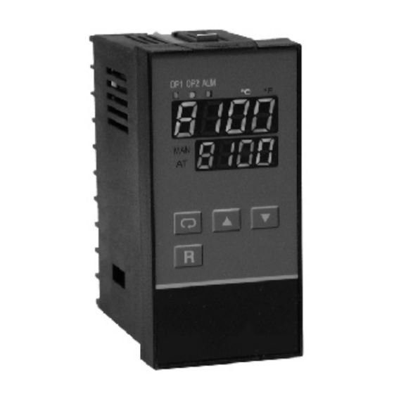
1- 3 Keys and Displays 1- 3 Keys and Displays KEYPAD OPERATION KEYPAD OPERATION SCROLL KEY : SCROLL KEY : This key is used to select a parameter to be viewed or adjusted. UP KEY : UP KEY : This key is used to increase the value of selected parameter. DOWN KEY : DOWN KEY : This key is used to decrease the value of selected parameter. - Page 10 Display program code of the product OP1 OP2 OP2 ALM for 2.5 seconds. The lower display shows program no. 6 for TC 48 with version 24. The program no. for TC 96 is 11. Figure 1.3 Figure 1.3 TC 48...
-
Page 11: Menu Overview
1- 4 Menu Overview 1- 4 Menu Overview User User Setup Setup Manual Manual Auto-tuning Auto-tuning Calibration Calibration menu menu menu menu Mode Mode Mode Mode Mode Mode 6.2 sec. 7.4 sec. 8.6 sec. 5 sec. 9.8 sec. PV, SV Release then press LOCK... -
Page 12: Parameter Descriptions
1-5 Parameter Descriptions 1-5 Parameter Descriptions Parameter Default Parameter Description Range Notation Value 25.0 C Set point for output 1 Low: SP1L High :SP1H (77.0 F) Set point for output 2 10.0 C Low: -19999 High :45536 when output 2 performs (18.0F) alarm function Set point for alarm or... - Page 13 Parameter Default Range Parameter Description Notation Value Degree C unit Input unit selection Degree F unit UNIT Process unit No decimal point 1 decimal digit Decimal point selection 2 decimal digits 3 decimal digits -17.8 C Input low scale value High: Low: -19999...
- Page 14 Parameter Default Range Parameter Description Notation Value 500.0 LC 10.0 C Proportional band value High: Low: 0 (900.0 LF) (18.0 F) Integral time value High: 1000 sec Low: High: Derivative time value Low: 360.0 sec 25.0 Reverse (heating ) control action Output 1 function OUT1 Direct (cooling)
- Page 15 Parameter Default Range Parameter Description Notation Value 500.0 C Ramp rate High: Low: 0 (900.0 F) : Output 2 No Function : Deviation High Alarm : Deviation Low Alarm Output 2 function OUT2 : Process High Alarm : Process Low Alarm : Cooling PID Function Relay output Solid state relay...
- Page 16 Parameter Default Range Parameter Description Notation Value Heating-cooling dead High: 36.0 % band (negative value= Low: -36.0 overlap) :No alarm function :Dwell timer action :Deviation high alarm :Deviation low alarm Alarm function for :Deviation band out of ALFN alarm output band alarm :Deviation band in band alarm...
- Page 17 Parameter Default Range Parameter Description Notation Value Address assignment of Low: 1 High: 255 ADDR digital communication 2.4 Kbits/s baud rate 4.8 Kbits/s baud rate 9.6 Kbits/s baud rate Baud rate of digital 14.4 Kbits/s baud rate BAUD communication 19.2 Kbits/s baud rate 28.8 Kbits/s baud rate 38.4 Kbits/s baud rate : 7 data bits...
- Page 18 Prameter Default Range Parameter Description Notation Value TD is put ahead O1HY is put ahead CYC1 is put ahead OFST is put ahead RR is put ahead Select 1st parameter for SEL1 O2HY is put ahead user menu CYC2 is put ahead CPB is put ahead DB is put ahead ADDR is put ahead...
-
Page 19: Chapter 2 Installation
Chapter 2 Installation Chapter 2 Installation Dangerous voltages capable of causing death may be Dangerous voltages capable of causing death may be present in this instrument. Before installation or beginning any present in this instrument. Before installation or beginning any cleaning or troubleshooting procedures the power to all cleaning or troubleshooting procedures the power to all equipment must be switched off and isolated. - Page 20 Figure 2.1 Mounting Dimensions Figure 2.1 Mounting Dimensions TC 96 Panel 45 mm 65 mm Panel 45 mm Panel TC 48 Cutout 11.5mm 104.8mm www.comoso.com...
-
Page 21: Wiring Precautions
2 - 3 Wiring Precautions 2 - 3 Wiring Precautions Before wiring, verify the label for correct model number and Before wiring, verify the label for correct model number and options. Switch off the power while checking. options. Switch off the power while checking. Care must be taken to ensure that maximum voltage rating Care must be taken to ensure that maximum voltage rating specified on the label is not exceeded. - Page 22 Figure 2.2 Lead Termination for Figure 2.2 Lead Termination for TC 96 TC 96 6.0mm max. Figure 2.3 Lead Termination Figure 2.3 Lead Termination for TC 48 for TC 48 3.0mm min. 50 C max. air ambient 50 C max. air ambient 90-250VAC 90-250VAC...
- Page 23 50 C max. air ambient 50 C max. air ambient Use copper conductors (except on T/C input ) Use copper conductors (except on T/C input ) Figure 2.5 Figure 2.5 Rear Terminal Connection for TC 48 Rear Terminal Connection for TC 48 www.comoso.com...
-
Page 24: Power Wiring
Near the controller a fuse and a switch rated at 2A/250VAC should be equiped as shown in the following diagram. 2A/250VAC should be equiped as shown in the following diagram. TC 48 TC 48 TC 96 TC 96... -
Page 25: Sensor Input Wiring
This error is far greater than controller error and cannot be corrected on the sensor except by proper selection and replacement. on the sensor except by proper selection and replacement. 2-6 Sensor Input Wiring 2-6 Sensor Input Wiring TC 48 TC 48 TC 96 TC 96 TC+, V+... - Page 26 TC 48 TC 48 TC 96 TC 96 Figure 2.9 Figure 2.9 Output 1 Relay to Drive Contactor Output 1 Relay to Drive Contactor TC 48 TC 48 TC 96 TC 96 Figure 2.10 Output 1 Figure 2.10 Output 1...
-
Page 27: Alarm Wiring
TC 48 TC 48 TC 96 TC 96 Load Load Figure 2.11 Output 1 Linear Current Figure 2.11 Output 1 Linear Current 2-8 Alarm Wiring 2-8 Alarm Wiring TC 48 TC 48 TC 96 TC 96 LOAD LOAD 120V/240VAC 120V/240VAC... -
Page 28: Chapter 3 Programming
Chapter 3 Programming Chapter 3 Programming Press for 5 seconds and release to enter setup menu. Press to select the desired parameter. The upper display indicates the parameter symbol, and the lower display indicates the selected value of parameter. 3-1 Lockout 3-1 Lockout There are four security levels can be selected by using LOCK parameter. -
Page 29: Control Outputs
process value INHI INLO input signal 3-3 Control Outputs 3-3 Control Outputs There are 4 kinds of control modes can be configured as shown in Table 3.1 Table 3.1 Table 3.1 Heat-Cool Control Setup Value Table 3.1 Heat-Cool Control Setup Value Control OUT1 OUT2... - Page 30 Dead band = O1HY SP1 O1HY Time OUT1 Action Time www.comoso.com...
- Page 31 Cool only control: Cool only control: www.comoso.com...
- Page 32 You can use the program for the new process or directly set the appropriate values for PB, TI & TD according to experience. If the control behavior is still inadequate, then use to improve the control. See for manual tuning. Adjustment of CPB is related to the cooling media used.
- Page 33 OUT2=DE.HI OUT2=DE.HI SV+SP2 SV+SP2-O2HY Time OUT2 Action Time SP2+O2HY Time OUT2 Action Time www.comoso.com...
-
Page 34: Alarm
The controller has one alarm output. There are 6 alarm functions and one dwell timer that can be selected, and four kinds of alarm modes ( ALMD ) are available for each alarm function ( ALFN ). Besides the alarm output, the output 2 can also be configured as another alarm. -
Page 35: Configure User Menu
Normal Alarm : ALMD = NORM Normal Alarm : ALMD = NORM When a normal alarm is selected, the alarm output is de-energized in the non-alarm condition and energized in an alarm condition. Latching Alarm : ALMD = L TCH Latching Alarm : ALMD = L TCH If a latching alarm is selected, once the alarm output is energized, it will remain unchanged even if the alarm condition is cleared. -
Page 36: Ramp
3 - 6 Ra mp 3 - 6 Ra mp www.comoso.com... -
Page 37: Dwell Timer
Alarm output can be configured as dwell timer by selecting TIMR for ALFN . As the dwell timer is configured, the parameter SP3 is used for dwell time adjustment. The dwell time is measured in minutes, int the range of 0.1 to 4553.6. Once the process reaches the set point the dwell timer starts to time down to zero (time out). -
Page 38: Pv Shift
Subject Subject Subject Heater Heater Heater Heat Heat Heat Transfer Transfer Transfer 165 C 165 C 200 C 200 C 200 C 235 C Sensor Sensor Sensor 35 C temperature Adjust SHIF Display is stable difference is observed SHIF= -35 C SHIF= -35 C SHIF= 0 Supply more heat... -
Page 39: Digital Filter
In certain application the process value is too unstable to be read. To improve this a programmable low pass filter incorporated in the controller can be used. This is a first order filter with time constant specified by parameter . The default value of FILT is 0.5 sec. before shipping. -
Page 40: Failure Transfer
The controller will enter as one of the following conditions occurs: occurs due to the input sensor break or input current below 1mA if 4-20 mA is selected or input voltage below 0.25V if 1-5 V is selected . occurs due to the A-D converter failure. Output 1 and output 2 will perform the function as the controller enters failure mode. -
Page 41: Auto-Tuning
1. The system has been installed normally. 2. Set the correct values for the setup menu of the unit. But don't use a zero value for PB and TI , otherwise, the auto-tuning program will be disabled. The LOCK parameter should be set at NONE. -
Page 42: Manual Tuning
The auto-tuning can be applied either as the process is warming up ( Cold Start ) or as the process has been in steady state ( Warm Start ). After the auto-tuning procedures are completed, the AT indicator will cease to flash and the unit revert to PID control by using its new PID values. -
Page 43: Manual Control
www.comoso.com... - Page 44 www.comoso.com...
-
Page 45: Chapter 4 Applications
Chapter 4 Applications Chapter 4 Applications An oven is designed to dry the products at 150 C for 30 minutes ° and then stay unpowered for another batch. A TC 96 equipped with is used for this purpose. The system diagram is shown as follows : OP1 OP2 OP2 ALM... -
Page 46: Cool Only Control
A TC 96 is used to control a refrigerator at temperature below 0 C. ° The temperature is lower than the ambient, a cooling action is required. Hence select DIRT for OUT1. Since output 1 is used to drive a magnetic contactor, O1TY selects RELY. A small temperature oscillation is tolerable, hence use ON-OFF control to reduce the over-all cost. -
Page 47: Chapter 5 Calibration
CALIBRATION SHOULD BE DONE ONLY BY EXPERIENCED PERSONNEL WITH APPROPRIATE CALIBRATION EQUIPMENT . THE USE OF A CERTIFIED CALIBRATION LABORATORY IS HIGHLY RECOMMENDED. FOR DETAILED CALIBRATION INSTRUCTIONS, OR FOR ADDITIONAL INFORMATION, PLEASE CONTACT YOUR LOCAL EATON REPRESENTATIVE OR CALL EATON CARE AT 877-ETN-CARE. www.comoso.com... -
Page 48: Chapter 6 Specifications
Chapter 6 Specifications Chapter 6 Specifications www.comoso.com... - Page 49 www.comoso.com...
- Page 50 Resolution : Resolution : www.comoso.com...
- Page 51 www.comoso.com...
- Page 52 www.comoso.com...
- Page 53 www.comoso.com...
-
Page 54: Error Codes
Display Error Error Description Corrective Action Symbol Code Illegal setup values been used: Check and correct setup values of Before COOL is used for OUT2, OUT2, PB, TI and OUT1. IF OUT2 DIRT ( cooling action ) has already is required for cooling control, the been used for OUT1, or PID mode control should use PID mode ( PB is not used for OUT1 ( that is PB... -
Page 55: Warranty
Eaton distributor or Eaton Care at 877-ETN-CARE. A charge is made for repairing after the expiration of the warranty. IN NO EVENT SHALL EATON BE LIABLE FOR CLAIMS BASED UPON BREACH OF EXPRESS OR IMPLIED WARRANTY OR NEGLIGENCE OR ANY... - Page 56 www.comoso.com...
Need help?
Do you have a question about the TC 48 and is the answer not in the manual?
Questions and answers