Advertisement
Table of Contents
- 1 Table of Contents
- 2 Vehicle Identification and Serial Numbers
- 3 Technical Characteristics
- 4 Controls and Instruments
- 5 Operating the Machine
- 6 Safety
- 7 Parking the Machine
- 8 Transporting the Machine
- 9 Periodic Maintenance Operations
- 10 Capacities
- 11 Greasing Points
- 12 Electric Circuit CH 200
- 13 Electric Circuit CH 250
- 14 Hydraulic Diagram (Side-Shift)
- 15 Hydraulic Diagram (Hydromatik) CH 200
- 16 Hydraulic Diagram (Hydromatik) CH 250
- Download this manual
See also:
Service Manual
Advertisement
Table of Contents

Related Manuals for AUSA CH 200


Summary of Contents for AUSA CH 200
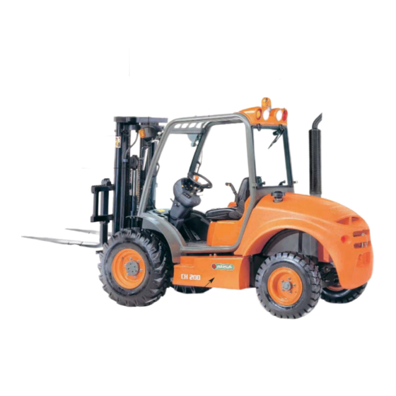
- Page 1 CH 200 CH 200 x4 CH 250 CH 250 x4 OPERATOR’S MANUAL ENGLISH...
- Page 2 AUSA Forklift CH 200 CH 200 4x4 CH 250 CH 250 4x4...
- Page 4 As wide variations in operating conditions may be experienced, you are urged to contact your AUSA Distributor to resolve any operational or service problems. Please have all operators of this forklift read and understand this Manual.
-
Page 5: Table Of Contents
CH 200 / CH 250 Index Identification of the forklift components Vehicle identification and serial numbers Technical characteristics Machine decals USA market Machine decals UK market Controls and instruments Instrument panel and controls (components) Instrument panel and controls (multifunction instrument) - Page 6 CH 200 / CH 250 Identification Term such as right, left, front and rear when used in this Operators Manual indicate the right and left sides of the machine, the front and back of the machine, as viewed from the operators of the forklift seat looking forward.
-
Page 7: Vehicle Identification And Serial Numbers
Vehicle Important! Writes your machine Model number, date of sale, chassis and engine serial num- ber in the spaces provided below. Give this information to your AUSA dealer when you need parts Identification or information for your machine. Make a record of these numbers in your files. -
Page 8: Technical Characteristics
Four cylinders, four stroke, water-cooled. Electrical starter. Mixed radiator (water/oil). CH 200: Isuzu 4LE2 - Tier II - Power 51HP (37.5 Kw in accordance with DIN 70020) or 46 HP (34.5 kw at 2,700 rpm in accordance with DIN 6270B). - Page 9 Electrical equipment Electrical starter 1,8 Kw (CH 200) and 1,4 Kw (CH 250). Pre-heating spark plugs. Alternator of 20A and regulator. Battery 12V - 70 AH. Horn. Rotating beacon. Back-up alarm. Engine oil level alarm. Hydraulic oil level alarm. Coolant temperature alarm.
- Page 10 CH 200 / CH 250 Technical Optional equipment characteristics *4 Wheel driving transmission *Standard lateral displacement. continuously engaged (compen system) *Super-elastic solid tyres. *Partially closed cab (front and rear windshield). *Extra wide tyres. *Closed cab with heating. *Lighting equipment. *Hydraulic shovels: 10.5 cu.ft and 14 cu.ft *Other masts and attachments are also available in option.
- Page 11 CH 200 / CH 250 Machine Information decals (USA market)
- Page 12 CH 200 / CH 250 Warning Machine decals (USA market) Load charts...
- Page 13 CH 200 / CH 250 Machine Information decals (UK market)
- Page 14 CH 200 / CH 250 Load graphs Machine decals (UK market)
-
Page 15: Controls And Instruments
The horn is activated by the button located on the left of the joystick (5). Speed control (fig.3) Only in CH 200 and CH 200 x4 Pushing the joystick switch button (4) the fast speed is connected/disconnected. When it is connected the fast speed lamp on the instrument panel is lit. - Page 16 CH 200 / CH 250 Components Instrument 1 - Multifunction Instrument (see next page) Panel 2 - Rotating beacon switch. To switch on, push the button, it will light, to switch off push the and controls button again. 3 - Parking brake switch. When the parking brake is applied, the button lits.
- Page 17 CH 200 / CH 250 Instrument Multifunction instrument Panel A - Hourmeter. This gauge indicates the total running time of the forklift engine to enable ser- vicing of the engine at proper intervals. (See Maintenance Chart for servicing frequency). and controls B - Fuel level.
-
Page 18: Operating The Machine
ATTENTION With ambient temperatures lower than 0ºC, AUSA recommends to run the engine at idle speed for 3 minutes before starting to work with the forklift in order to reach the appropiate fluency on the engine and hydraulic oil... - Page 19 Chart located on the left mudguard. With load centre at 20 in or 500mm (European and ISO standards), the CH 200 has a rated capacity of 4,384lbs or 2000Kg and the CH 250 has a rated capacity of 5,48lbs or 2,500Kg.
- Page 20 CH 200 / CH 250 Operating Lifting Capacity Machine stability is maintained only when the forklift handles loads within its rated lifting capacity the machine and the various conditions listed above. The lifting capacity of the machine is determined by the safe height and weight limits of the load.
- Page 21 ONLY ON CH 200 (speed control)
-
Page 22: Safety
CH 200 / CH 250 Safety WARNING Do not operate this machine unless you have read and understand the safety and operational instructions contained in this Operators Manual and have been instructed and trained in the safe operation of this Forklift. - Page 23 CH 200 / CH 250 Safety Before starting and operating the forklift · Stay alert. Concentrate fully on your work. Your safety and that of others depends on the care you take when operating this forklift. · Remember that you are the key to safety. Good safety practices not only protect you but also the people around you.
- Page 24 CH 200 / CH 250 Safety · Be certain you have good visibility at all times. It is important that you can see clearly both forward and back- ward when operating the forklift. If the load does not allow clear forward visibility, then drive with caution in rever- se.
- Page 25 CH 200 / CH 250 Safety · When operating on modest inclines or slopes: (fig.12) - Move very carefully and slowly. - Keep the forks and load low. - Keep the forks facing uphill at all times. This means reversing backwards down a slope to main- tain maximum load stability.
- Page 26 CH 200 / CH 250 Safety · Always drive with the forks in the low position and with the mast tilted slightly back. · Make certain that long or wide loads are fastened together so as to be stable and secure.
-
Page 27: Parking The Machine
CH 200 / CH 250 Parking Parking the machine and stopping the engine the machine Make certain that the forklift is parked on level ground when leaving it overnight. Also park it on level ground before any scheduled maintenance is attempted. Lower the forks to the ground, apply the parking brake and push directional switch to neutral. -
Page 28: Transporting The Machine
CH 200 / CH 250 Transporting Fastening the forklift to a lorry or trailer bed. (fig.1) When transporting the forklift on a trailer or truck bed, carefully follow the instructions in the the machine Caution Decal. Move slowly and carefully up (or down) the loading ramps. Once on the trailer make certain the forks are lowered, handbrake applied and the forks and tires are blocked. - Page 29 CH 200 / CH 250 Transporting Towing the machine If the machine must be towed for short distances, only do so with a solid tow-bar to prevent any the machine lateral sway. Attach the tow bar to the bolt at the rear of the counter weight (fig.2). Drive slowly and carefully at a speed not exceeding 6 mph.
-
Page 30: Periodic Maintenance Operations
- Only use OEM (Original Equipment Manufacturer) parts obtained from your AUSA dea- ler. Be certain to use the right type and size of tires. Never use split rims, (rims that are formed by 2 halves which are screwed together). - Page 31 CH 200 / CH 250 Periodic Machine cleaning During the clean operations, not to direct pressure water on the intake (air filter), the steering Maintenance column, battery, alternator and other electric devices because can deteriorate their components. Operations Breakdown in road (fig.1) In case of breakdown when driving on public roads, warn other users of the road with the hazard warning triangles.
- Page 32 This machine has a brake which doesn’t need any maintenance. If the brake pedal (fig.3) down so much, contact your AUSA dealer for bleeding operation or replacement of the internal disks. The only service needed in the brake circuit is to replace the fluid according with the mantenan- ce chart.
- Page 33 CH 200 / CH 250 Periodic Oil level of the power take-off (fig.1) To check the oil level in the transfer box, place the machine on level ground. Remove plug (2) to Maintenance see if the oil is just below this level hole. Add oil if necessary trough plug (1).
- Page 34 CH 200 / CH 250 Periodic Hydraulic steering and load handling safety valves (fig.1 and 2) There are safety relief valves on both the hydraulic steering block and on the load handling cir- Maintenance cuit. The lines in figure 1 and 2 show the plugs where the hydraulic steering pressure (1) and the load control hydraulic pressure (2) are adjusted.
-
Page 35: Capacities
CH 200 / CH 250 Capacities UK gal US gal Liters ISUZU and KUBOTA engine 1.59 1.91 7.25 Reductor box 0.30 0.40 Axles (differential housings) 0.44 0.53 Wheel reduction gears 0.18 0.21 Fuel tank (fig.1) 13.2 Hydraulic Oil tank 10.3 12.4... -
Page 36: Greasing Points
CH 200 / CH 250 Greasing Greasing points Rear axle points 1 nipple in the frame articulation axle. 2 WD models:(fig.1) 1 nipples in axle articulation 2 nipples, 1 on each wheel kingpin. 4 WD models: 4 nipples, 2 on each articulation of the wheel reduction gears. -
Page 37: Electric Circuit Ch 200
CH 200 / CH 250 Electric circuit CH200... - Page 38 CH 200 / CH 250 Electric circuit CH200...
- Page 39 CH 200 / CH 250 Electric circuit CH200...
- Page 40 CH 200 / CH 250 Electric circuit CH200...
- Page 41 CH 200 / CH 250 Electric circuit CH200 Item Description Item Description Pre-heat relay Rear wiper motor Horn Electric fuel pump Left hand headlight Starter motor Right hand headlight Windscreen washer motor Low beam fuse (10A) Instrument panel High Beam fuse (10A)
-
Page 42: Electric Circuit Ch 250
CH 200 / CH 250 Electric circuit CH250... - Page 43 CH 200 / CH 250 Electric circuit CH250...
- Page 44 CH 200 / CH 250 Electric circuit CH250...
- Page 45 CH 200 / CH 250 Electric circuit CH250...
- Page 46 CH 200 / CH 250 Electric circuit CH250 Item Description Item Description Pre-heat relay Rear wiper motor Horn Electric fuel pump Left hand headlight Starter motor Right hand headlight Windscreen washer motor Low beam fuse (10A) Instrument panel High Beam fuse (10A)
-
Page 47: Hydraulic Diagram (Side-Shift)
CH 200 / CH 250 Hydraulic diagram (Side-shift) -
Page 48: Hydraulic Diagram (Hydromatik) Ch 200
CH 200 / CH 250 Hydraulic diagram (Hydromatik) CH200... -
Page 49: Hydraulic Diagram (Hydromatik) Ch 250
CH 200 / CH 250 Hydraulic diagram (Hydromatik) CH250... - Page 50 CH 200 / CH 250...
Need help?
Do you have a question about the CH 200 and is the answer not in the manual?
Questions and answers