
Subscribe to Our Youtube Channel
Related Manuals for Tropos Networks 7320


Summary of Contents for Tropos Networks 7320
- Page 1 ® Tropos Networks Mesh Router Outdoor Installation Guide Model 7320 Tropos Networks, Inc. 555 Del Rey Ave. Sunnyvale, CA 94085 USA www.troposnetworks.com Part No. 200345-00 Rev C0 408-331-6800 November 2009...
-
Page 2: Copyright Notice
Consult the dealer or an experienced radio/TV technician. This Part 15 radio device operates on a non-interference basis with other devices operating at this frequency. Any changes or modification to said product not expressly approved by Tropos Networks could void the user's authority to operate this device. - Page 3 It is important for users of this equipment to participate in reuse, recycling, and other forms of recovery. The potential effects on the environment and human health as a result of the presence of hazardous substances in electrical and electronic equipment are a waste of natural resources and cause pollution. Tropos 7320 Router Installation Guide...
- Page 4 European Community Language Versions of Informal Statement for Inclusion in User Information The following statements are in accordance with Article 6.3 of Directive 1999/5/EC. Tropos 7320 Router Installation Guide...
-
Page 5: Important Safety Instructions
Risk of personal injury or death when installing this device! There is a risk of personal injury or death if the router antennas come near electric power lines. Carefully read and follow all instructions in this manual. By nature of the Tropos 7320 Router Installation Guide... - Page 6 NOT be exposed to any temperatures higher than 85 degrees C. The RJ45 connectors of the Tropos 7320 router may source DC power on pins 4,5 and 7,8. The IEEE 802.3 standards allow for pins 4,5 and 7,8 to be used for Power Over Ethernet.
- Page 7 The Tropos 7320 router can only be used with approved antennas. See Appendix C, “Approved Antenna Configurations and Attenuation Settings” for further information. Surfaces may become hot. Use caution when accessing the Tropos 7320 router. Tropos 7320 Router Installation Guide...
-
Page 8: Table Of Contents
Tropos 7320 Router — ETSI ......2 Tropos 7320 DC Router........3 Preparing for Installation. - Page 9 Index ............87 Tropos 7320 Router Installation Guide...
- Page 10 Tropos 7320 Router Exploded View ........4...
- Page 11 Tightening the Clamps ......... . . 83 Tropos 7320 Router Installation Guide...
- Page 12 Tropos 7320 Router Models—FCC ........2...
-
Page 13: Installing The Router
Installing the Router ® This guide explains how to install the Tropos 7320 Mesh router safely and is intended for trained technical professionals. This chapter covers the following topics: “Product Summary” on page 2 “Preparing for Installation” on page 3 “Mounting Strategies”... -
Page 14: Product Summary
Tropos 7320 DC Router Preparing for Installation Tropos 7320 Router — FCC The Tropos 7320 router for the FCC regulatory domain has the following characteristics: 802.11a/b/g/n dual band, 2400-2483 MHz/5470-5850 MHz Support for 802.11a/b/g/n clients AC power, 100-480 VAC, 50/60 Hz... -
Page 15: Tropos 7320 Dc Router
7320: 2.4 & 5.4 GHz, DC Power, NoBatt, ETSI Preparing for Installation The Tropos 7320 router must be installed by a trained professional, value added reseller, or systems integrator who is familiar with RF planning issues and regulatory limits defined by the governing body of the country in which the unit will be installed. -
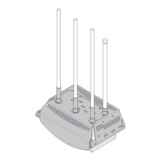
Page 16: Tropos 7320 Router Exploded View
Chapter 1 Tropos 7320 Router Exploded View FIGURE 1 802.11b/g/n Tx/Rx antenna 802.11b/g/n Pole bracket Rx antennas 802.11a/n Tx/Rx antenna #10-32 Sun shield hex head 5/16" Hose machine screws clamps AC input power connector Router Connector access cover Quick tie... -
Page 17: Installation Hardware And Tools
Wood pole mounting only: two 1/4-inch diameter, 3 1/2-inch long lag bolts Site Planning To ensure safe and durable wiring, installation of the Tropos 7320 router must follow appropriate electrical and building codes. Follow the National Electrical Code (NEC) requirements, unless local codes in your area take precedence over the NEC code. -
Page 18: Location Guidelines
Chapter 1 Location Guidelines The Tropos 7320 router is a radio devices and therefore susceptible to interference that can reduce throughput and range. Follow these guidelines to ensure the best performance: Install the unit in an area where trees, buildings, and large steel structures do not obstruct radio signals to and from the antenna. -
Page 19: Power Source
Make sure that grounding is complete before you connect power to the router. Safety Installing the Tropos 7320 router can pose a serious hazard. Be sure to take precautions to avoid the following: Exposure to high voltage lines during installation... -
Page 20: Mounting Strategies
2. In each case the router is mounted to assure clearance for the antennas above the height of the streetlight. Example Mounting Location - Antennas Facing Upward FIGURE 2 Antennas clear of obstruction Antennas clear of obstruction trp_197 Tropos 7320 Router Installation Guide... -
Page 21: Proper Use Of Hose Clamps
Chapter 1 Proper Use of Hose Clamps The mounting assembly for the Tropos 7320 router contains hose clamps to secure the router to the mounting structure. Figure 3 illustrates the proper use of the hose clamps. The clamps must be routed through slots in the pole bracket as shown in the figure, and then attached to the pole and tightened. -
Page 22: Pole, Tower, And Streetlight Mounting Instructions
Chapter 1 Pole, Tower, and Streetlight Mounting Instructions This section explains how to mount the Tropos 7320 router on a pole, tower, or streetlight. It is best to mount the router to aluminum or galvanized steel structures. The mounting brackets are designed to pierce any oxidation layers that are on the outside of the pole, thereby assuring good quality connection to the grounded structure. -
Page 23: Metal Pole Mounting
Figure 4 illustrates the proper method of mounting the router on an outdoor metal pole. Note Antennas must be clear of obstruction. Metal Pole Mounting FIGURE 4 Pole bracket (rotated) Sun shield trp_097 Router trp_153 trp_198 Tropos 7320 Router Installation Guide... -
Page 24: Sun Shield Connections
To continue installing the router, see “Connecting Cable Attached Antennas” on page 18. Sun Shield Connections FIGURE 5 Screws to attach router to sun shield Bubble level Use machine screws to attach sun shield to pole bracket trp_154 Tropos 7320 Router Installation Guide... -
Page 25: Wood Pole Mounting
Chapter 1 Wood Pole Mounting Figure 6 shows a typical installation with the router mounted on an outdoor wood pole. Note Antennas must be clear of obstruction. Wood Pole Mounting FIGURE 6 Sun shield Router trp_208 Tropos 7320 Router Installation Guide... -
Page 26: Wood Brace Mounting
Wood Brace Mounting You can mount the pole bracket directly on a wood brace without using pole hose clamps, as shown in Figure Wood Brace Mounting Option FIGURE 7 1/4" lag bolts 3-1/2" minimum Wood brace trp_141 Tropos 7320 Router Installation Guide... -
Page 27: Tower Mounting
You can mount the router on an outdoor tower. Note At the antenna level, the router must be free from metal obstruction within a 4-foot radius (Figure Tower Mounting FIGURE 8 Channel stock Brackets not included trp_199 Tropos 7320 Router Installation Guide... - Page 28 Tighten the mounting bolts. Slide the router into place and secure it at the end with four #10-32 hex head machine screws. To continue installing the router, see “Connecting Cable Attached Antennas” on page 18. Tropos 7320 Router Installation Guide...
-
Page 29: Streetlight Mounting
Use the hose clamps to attach the pole bracket to the streetlight. Depending upon the diameter of the pole, you may need to use 2 small clamps, 2 large clamps, or 2 pairs of large clamps joined together to reach around the pole. Tropos 7320 Router Installation Guide... -
Page 30: Connecting Cable Attached Antennas
18. Connecting Cable Attached Antennas This section applies to external antennas used with the Tropos 7320 router. You can mount the antenna on a structure and then use cables to attach it to the router. After mounting, secure the antennas with ThreadLocker Loctite 242 and waterproof them using self-fusing EPR tape. -
Page 31: Connecting External Antennas
Antenna(s) must be installed by a trained professional. Operating the unit with non-qualified antennas is a violation of U.S. FCC Rules Part 15.203(c), Code of Federal Regulations, Title 47. See “Approved Antenna Configurations and Attenuation Settings” on page 54 for a listing of antenna options. Tropos 7320 Router Installation Guide... -
Page 32: Waterproofing Antenna Connections
Separate the liner from the tape. Pre-stretch the tape and wrap it tightly around the connector. Waterproofing Antenna Connections FIGURE 11 Apply 2 drops of Loctite to threads Apply tape around RF cable joints trp_202 Tropos 7320 Router Installation Guide... -
Page 33: Installing Attached Antennas
The grounding arrangement for the router is shown in Figure Grounding Arrangement FIGURE 12 Grounding screw Grounding strap on pipe or grounding rod 10 AWG wire to ground trp_104 Tropos 7320 Router Installation Guide... -
Page 34: Grounding The Data Protection Device
Grounding the Indoor Network Protection Unit FIGURE 13 To network Shielded RJ45 ports Data cable enters Indoor network building wall protection unit through conduit Grounding wire to elecrtical outlet ground 10 AWG wire or water pipe to ground trp_140 Tropos 7320 Router Installation Guide... -
Page 35: Connecting Ac Power
Summary Examples CAT C Outside and service • Service drop from pole to building entrance entrance • Run between meter and distribution panel • Overhead line to detached buildings • Underground lines to well pumps Tropos 7320 Router Installation Guide... - Page 36 Outlets and long branch • All outlets at more than 10 m (30 ft) from Category B with circuits wires #14-10 • All outlets at more than 20 m (60 ft) from Category C with wires #14-10 Tropos 7320 Router Installation Guide...
-
Page 37: Ieee/Ansi C62.41 Power Categories
FIGURE 14 Outdoor units powered from Category C distribution panel are in Overvoltage Installation Category B Category A Category B Outdoor units powered from electrical meter are in Overvoltage Installation Category C Category C trp_164 trp_207 Tropos 7320 Router Installation Guide... -
Page 38: Connecting To Ac Power (Category C)
Connect the AC cable to the router and tighten the nut hand-tight. See Figure Connect the router to a 100-480 VAC 50/60 Hz CAT C power source. Reenergize the circuit and confirm that power to the router comes on. Tropos 7320 Router Installation Guide... -
Page 39: Connecting To Streetlight Power (Category C)
The NEMA twist-lock adapter can be used only with UL 773 listed outdoor lighting controls rated for and operated at 100-480 VAC 50/60 Hz. Warning Be extremely careful when connecting to Category C streetlight power. Tropos 7320 Router Installation Guide... -
Page 40: Connecting Streetlight Power
Connect the photosensor to the top of the NEMA 3 prong plug. Connect the AC plug to the router and tighten hand-tight. Reenergize the circuit and confirm that power to the router comes on. Tropos 7320 Router Installation Guide... -
Page 41: Connecting Dc Power
Closure caps should be tightened to be snug. Connecting DC Power The Tropos 7320 DC router is designed for direct DC power connection. The AC power connector is capped; the DC terminal block is located in the connector access area. -
Page 42: Tropos 7320 Dc Router Connections
Chapter 1 Tropos 7320 DC Router Connections FIGURE 18 Watertight access cover cable glands 4, 5 & 7, 8 twisted pairs to DC terminal block; 10" service loop Connector access cover Shield termination Tighten six screws to fasten access cover... -
Page 43: Dc Terminal Block Location
DC terminal block trp_175 Note PoE output and battery back-up are not supported on the Tropos 7320 DC router. Connect DC power to the router Warning Verify that the DC power source is off before attaching DC power cables. Mount the router according to the appropriate mounting instructions (“Pole, Tower, and... -
Page 44: Connecting A Data Port
The router is equipped with two Ethernet ports that support RJ45 connectors. Note The router is shipped pre-configured. For post-installation changes in configuration, you can communicate with the router by way of its wireless connection. For more information, see the Tropos Networks Configuration Guide. Note Only use shielded Cat5 cable rated for outdoor use. -
Page 45: Options For Connecting A Data Port
Use the RJ45 jacks for port connection. Options for Connecting a Data Port FIGURE 21 Watertight access cover cable glands Shield termination Cable terminated with RJ45 jack for port connection trp_111 Tropos 7320 Router Installation Guide... - Page 46 Remove the connector access cover on the bottom of the router. Run raw cables for the Management or LAN port, or both, through the bulk head openings, allowing sufficient length to terminate the cables without causing crowding in the connection area. See Figure Tropos 7320 Router Installation Guide...
-
Page 47: Data Port Connection
The outer jacket and conductive shield must be stripped to expose the twisted pairs for attachment, as shown in Figure 22. The proper location of the connections on the circuit board is shown in Figure Verify that the protection unit is properly grounded. Tropos 7320 Router Installation Guide... -
Page 48: Resetting The Router
Follow these steps if AC power is off and the router is running on battery power: Remove the connector access cover on the bottom of the router. Press and hold the Reset button for 3-5 seconds. Tropos 7320 Router Installation Guide... -
Page 49: Connecting Peripherals
Chapter 1 Connecting Peripherals The Tropos 7320 router can be configured to source DC power on the Ethernet connector pins 4,5 and 7,8, This capability allows the router to power remote peripherals such as backhaul point-to-point radios, video cameras, or fiber optic transceivers. The Tropos Power over Ethernet (PoE) power sourcing capability is a fully isolated supply and can be used to power either positive or negative polarity peripherals. -
Page 50: Rj45 Pin Descriptions For Data Connection
Only use shielded Cat5 cable rated for outdoor use. For protection against risk of fire, electrical hazard and to ensure the reliable operation of this equipment, the shields of the Cat5 cable must be properly terminated and bonded to the unit and to the protective earth (PE) at the building entrance. Tropos 7320 Router Installation Guide... -
Page 51: Battery Backup Operation
Chapter 1 Battery Backup Operation The Tropos 7320 router may contain an automatically recharging battery, which provides an integrated uninterruptible power supply (UPS). The available backup time depends upon the level of network traffic serviced by the router and the ambient temperature. -
Page 52: Safety Information
RF electromagnetic energy emitted by FCC certified equipment. The Tropos 7320 routers meet the uncontrolled environmental limits found in OET- 65 and ANSI C95.1, 1991. Proper operation of this device according to the instructions found in this manual and the hardware and software guides on the router results in user exposure that is substantially below the FCC recommended limits. -
Page 53: Safety Guidelines
The information in this section is intended for trained service personnel only. DC Fuse The Tropos 7320 DC router has a serviceable fuse that can be replaced by qualified service personnel. Replace only with Littelfuse # 0154005.DRT. (See “Installation Accessories”... - Page 54 Replace the fuse using the same tool. Replace and connector access cover and power-up the router. Warning Risk of fire, electric shock, or personal injury. Replace only with a fuse of the same type and rating. Tropos 7320 Router Installation Guide...
-
Page 55: Power Consumption
LAN or Management port of the Tropos 7320 router. Temperature can also influence the power consumption for units configured with battery backup, due to the internal freeze protection capability associated with the internal battery module. -
Page 56: Ac Power Consumption: -40°C, Battery Backup
Chapter 2 7320 AC Power Consumption: -40°C, Battery Backup FIGURE 28 7320 AC Power Consumption: -40°C, with Battery Backup, No PoE Tropos 7320 Router Installation Guide... - Page 57 Chapter 2 DC Power Consumption Figure 29 shows the relationship between traffic load and DC power consumption. Figure 29 DC Power Consumption Tropos 7320 Router Installation Guide...
-
Page 58: Product Specifications
Product Specifications The tables in this chapter contain specifications for the Tropos 7320 router: “Physical Specifications - Tropos 7320 Router” on page 46 “Interfaces” on page 48 “Power Options / Consumption” on page 51 “Power Over Ethernet - Power Sourcing”... - Page 59 Chapter 3 Physical Specifications - Tropos 7320 Router (continued) TABLE 7 Specification Value Projected Area 0.8 sq. ft. (115 sq. in.) Corrosion Resistance ASTM B117 Salt Fog Color Router color Gloss white Status Lamp Indicator colors Red/Green/Blue Shock and Vibration...
-
Page 60: Interfaces
-89dBm @ 36 Mbps -96dBm @ 6 Mbps -85dBm @ 48 Mbps -96dBm @ 12 Mbps -84dBm @ 54 Mbps Tx Power ETSI/EU 5dBm-20dBm (EIRP) set in 1dB units FCC/IC 21dBm-36dBm (EIRP) set in 1dB units Tropos 7320 Router Installation Guide... - Page 61 FCC/IC 21dBm-36dBm (EIRP) set in 1dB units Rx Saturation -30dBm (6 Mbps) Maximum Power at Antenna -30dBm (9 Mbps) Port -30dBm (12 Mbps) -30dBm (18 Mbps) -30dBm (24 Mbps) -35dBm (36 Mbps) -35dBm (48 Mbps) -35dBm (54 Mbps) Tropos 7320 Router Installation Guide...
- Page 62 Interfaces (continued) TABLE 8 Specification Value Antennas Antennas External Antenna Diversity 802.11b/g/n: 1 Tx and 3 Rx. Maximum Ratio Combining (MRC) receiver 802.11a/n: No diversity Impedance 50 ohms VSWR 1.5 : 1 Connectors (three) N (female) Tropos 7320 Router Installation Guide...
-
Page 63: Power Options / Consumption
EN61000-4-2 Level 4 ESD Immunity EN61000-4-5 Level 4 Surge Immunity EN61000-4-4 Level 4 EFT Immunity Integrated Branch Circuit Protection Class CC-Fuse: Littlefuse KLDR Time- Delay 20A Integrated Branch Circuit Protec- Class CC-Fuse: Littlefuse KLDR Time-Delay 20A tion Tropos 7320 Router Installation Guide... -
Page 64: Power Over Ethernet - Power Sourcing
EN61000-4-2 Level 4 ESD Immunity EN61000-4-4 Level 4 EFT Burst Immunity EN61000-4-3 EMC Field Immunity ETSI EN 301 489-17 ETSI EN 300 328 EN 60950-1, IEC 60950-1 CISPR 22 Class B Canada Industry Canada RSS210 Tropos 7320 Router Installation Guide... -
Page 65: Power Options / Consumption - Tropos 7320 Dc Router
Chapter 3 Tropos 7320 DC Router Specifications Power Options / Consumption - Tropos 7320 DC Router TABLE 12 Specification Value DC Input Power 12-60Vdc 3.5A - 0.7A max Power Consumption 12W typical 21W maximum DC fuse Littlefuse 0154005. DRT 5A, slow blow... -
Page 66: Approved Antenna Configurations And Attenuation Settings
Note To reduce potential radio interference to other users, the antenna type and its gain should be so chosen that the Effective Isotropic Radiated Power (EIRP) is not more than that permitted for successful communication. Tropos 7320 Router Installation Guide... -
Page 67: B/G/N Antenna Configurations (2400-2483 Mhz)
Use the following formulas to compute the required attenuation level: Gain’ (dBi) = Antenna Gain (dBi) - Cable Loss (dB) 802.11b/g/n: Tx Antenna Setting (dB) = if Gain’ < 7 dBi Gain’ - 7 if Gain’ > 7dBi 802.11a/n point-to-multipoint: Tropos 7320 Router Installation Guide... -
Page 68: Standard Power Product Antennas
Antenna Ordering Number Power (dBm) Setting (dB) EIRP 6.0dBi omni, unit mounted AN060077 13.7 19.7 7.4dBi omni, unit mounted AN074077 12.1 19.5 10.0dBi omni, unit mounted AN100022 19.3 12.0dBi sector, external bracket AN120044 19.5 mounted Tropos 7320 Router Installation Guide... -
Page 69: 802.11A/N Radio (5470-5725 Mhz) - Antenna Configurations
Tx Antenna Setting (dB) = if Gain’ < 7 dBi Gain’ - 3 if Gain’ > 7dBi 802.11a/n: Tx Antenna Setting (dB) = if Gain’ < 9 dBi Gain’ - 9 if Gain’ > 9 dBi Tropos 7320 Router Installation Guide... -
Page 70: Antenna Specifications And Patterns
Antenna Specifications and Patterns Table 18 provides antenna specifications and patterns for the Tropos-supplied antennas. Tropos 7320 Router Installation Guide... -
Page 71: Antenna Specifications And Patterns
• N connector • 2400-2483 MHz • Length: 11.9 in (30.3 cm) • Weight: 4.4 oz (.125 kg) • Color: White • Measured peak gain: 5.3dBi • Connector type: N male Azimuth Tropos 7320 Router Installation Guide... - Page 72 • N connector; bracketry • 2400-2483 MHz • Length: 19 in (48.3 cm) • Weight: 4.7 oz (.133 kg) • Color: White Azimuth • Measured peak gain: 7.1dBi • Connector type: N male Tropos 7320 Router Installation Guide...
- Page 73 • N connector; bracketry • 2400-2483 MHz • Length: 45 in (114.3 cm) • Weight: 20 oz (.57 kg) • Color: White • Measure peak gain: 9.9dBi • Connector type: N female Azimuth Tropos 7320 Router Installation Guide...
- Page 74 • Length: 34 in (86.4 cm) • Width: 3 in (7.6 cm) • Depth: 1.2 in (3.0cm) • Weight: 25.6 oz (.73 kg) • Color: Gray • Measured peak gain: 12.0dBi • Connector type: N female Azimuth Tropos 7320 Router Installation Guide...
- Page 75 • N connector • 5470-5850 MHz • Length: 17.5 in (43.2 cm) • Weight: 4.7 oz (.133 kg) • Color: White • Connector Type: N Male • Antenna gain: 8dBi (5470-5725 MHz) 9.1dBi (5725-5850 MHz) Azimuth Tropos 7320 Router Installation Guide...
- Page 76 • Length: 14.5 in (370 cm) • Width: 6.7 in (170 cm) • Depth: 2.5 in (65 cm) • Weight: 2.2 lbs (1 kg) • Color: gray • Measured peak gain: 15.3dBi • Connector Type: N Female Azimuth Tropos 7320 Router Installation Guide...
- Page 77 • Length: 7.45 in (189 cm) • Width: 7.45 in (189 cm) • Depth: 1.37 in (35 cm) • Weight: 1.6 lbs (0.72 kg) • Color: gray • Measured peak gain: 17.3dBi • Connector Type: N Female Azimuth Tropos 7320 Router Installation Guide...
- Page 78 • Length: 14.5 in (370 cm) • Width: 6.7 in (170 cm) • Depth: 2.5 in (65 cm) • Weight: 2.2 lbs (1 kg) • Color: gray • Measured peak gain: 17.0dBi • Connector Type: N Female Vertical Tropos 7320 Router Installation Guide...
- Page 79 • Length: 7.45 in (189 cm) • Width: 7.45 in (189 cm) • Depth: 1.37 in (35 cm) • Weight: 1.6 lbs (0.72 kg) • Color: gray • Measured peak gain: 19.0dBi • Connector Type: N Female Vertical Tropos 7320 Router Installation Guide...
-
Page 80: Installation Accessories
Hyperlink HGLN-CAT5-1 www.hyperlinktech.com Data and PoE Protection Device Polyphase NX4-60 Talley Communications, www.talleycom.com POLNX4-60 Inc. Yellow 3-Pin Mini-Link AC Plug McMaster-Carr 321K16 www.mcmastercarr.com Female Pig Tail Unterminated 12 Anti-seize lubricant Loctite 37230 McMaster Carr www.mcmaster.com Tropos 7320 Router Installation Guide... -
Page 81: Tropos Antennas, Cables, And Related Ordering Numbers
RC008000 Sealing Kit - Loctite242, EPR Rubber Splicing Tape RC008100 N connector cover/cap, outdoor, water tight RC009000 N adapter for 7.4dBi Mast-mounted antenna to N (male) cable SA006801 Indoor Cat 5 data cable surge protector Tropos 7320 Router Installation Guide... - Page 82 Tropos 7320 input power cable - watertight plug; 3-wire; 6 ft. PT031030 Tropos 7320 input power cable - watertight plug; 3-wire; 30 ft. PT032030 Tropos 7320 input power cable - pigtail, 3-wire, 30 ft., for EU markets EC003500 Tropos 7320 weathertight gateway connector kit EC003600...
-
Page 83: Ac Wiring Diagrams
AC Wiring Diagrams This chapter contains wiring diagrams for AC power: “AC Wiring — Photoelectric Power Tap” on page 72 “AC Wiring Power Cable 120VAC, 15A Plug” on page 73 Tropos 7320 Router Installation Guide... - Page 84 Control / UL773 (male) (female) 208Vac three phase; two wire service (grounded-Wye) Router North White Black North Black 480Vac NEMA Photoelectric Control / UL773 NEMA Photoelectric Power-Tap Adapter Control / UL773 Protective Earth (male) (female) 277Vac trp_204 Tropos 7320 Router Installation Guide...
-
Page 85: Ac Wiring Power Cable 120Vac, 15A Plug
3 - White White Protective Earth 16/3 SOOW Green or Green/Yellow L1 Black Black Router 120Vac single phase; three wire service Input Power Black Black (L1) Cable White White (N) Neutral Green Green Protective Earth trp_205 Tropos 7320 Router Installation Guide... -
Page 86: Wind Loading Considerations
1 square foot. Pole manufacturers have advised Tropos Networks that small communications devices such as Tropos routers do not present any significant static or dynamic load to these structures. -
Page 87: Canopy Installation Instructions
Canopy Installation Instructions The Canopy Subscriber Module and Bracket kit allows you to attach the Motorola Canopy Subscriber Module to the Tropos 7320 router. The kit includes the following items: Outdoor CAT5 weatherproof cable Bracket (metal pole) Screws #6-32 x 1.5"... -
Page 88: Canopy Assembly
#6-32 x 1.5" Canopy bracket Lock washers Screws Alternate #6-32 x 1.5" radio installation Cable ties Canopy radio subscriber Drip loop module 4' weatherproof cable Cable ties Finished installation Cable access cover Drip loop trp_206 Tropos 7320 Router Installation Guide... -
Page 89: Canopy Cable Wiring
Chapter 9 Canopy Cable Wiring TABLE 21 Canopy SM (RJ45) Color Router Signal Orange TXD+ Orange-White TXD- Blue RXD+ Green 24Vdc+ Green-White 24Vdc+ Blue-White RXD- Brown 24Vdc_RTN Brown-White 24Vdc_RTN Shield Drain wire Shield Shield Tropos 7320 Router Installation Guide... -
Page 90: Cable Termination Instructions
Cable Termination Instructions Follow these steps to prepare and terminate cables connected to the Tropos 7320 router: Strip off the outer sheath of cable to expose 6 inches of the inner cable or twisted pairs. The shield may be armored, braided or foil type depending upon cable type (see Table 33). -
Page 91: Cable Gland Assembly
RJ45 port 8765432 RJ45 jack trp_109 TIA/EIA 5688 Wiring - RJ-45 Pin Descriptions for Data Connection TABLE 22 Signal Color Description TXD+ Orange-White TX Data 10/100BaseT TXD- Orange TX Data 10/100BaseT RXD+ Green-White RX Data 10/100BaseT Tropos 7320 Router Installation Guide... - Page 92 PoE+ Blue-White Power output, 0, 12, 24, 48 Vdc (+) RXD- Green RX Data 10/100BaseT PoE- Brown-White Power output, 0, 12, 24, 48 Vdc (-) PoE- Brown Power output, 0, 12, 24, 48 Vdc (-) Tropos 7320 Router Installation Guide...
-
Page 93: Strand Mount Kit Installation Instructions
Strand Mount Kit Installation Instructions This appendix explains how to install the Tropos 7320 router on a cable strand using the Arris/ Monarch bracket strand mount kit. Kit Contents The kit (order number MB007000) contains the following items: Strand mount straps Sun shield mounting brackets 5/16"... -
Page 94: Attaching Strand Mount Brackets
Hang the router assembly on the cable strand. Tighten the clamps, ensuring that the router assembly is level and as close to the strand as possible. To make minor adjustments in placement, bend or tweak the strand mount straps, as required. Tropos 7320 Router Installation Guide... -
Page 95: Tightening The Clamps
Chapter 11 Tightening the Clamps FIGURE 39 Clamp You can now connect and power up the router according to the instructions in Chapter 1, “Installing the Router.” Tropos 7320 Router Installation Guide... -
Page 96: Abbreviations
Complementary Code Keying Conformite Europeene Code of Federal Regulations CISPR International Special Committee on Radio Interference Canadian Standard Association Decibels Decibels Relative to an Isotropic Radiator Decibels Referred to 1 Milliwatt DBPSK Differential-Binary Phase-Shift Keying Direct Current Tropos 7320 Router Installation Guide... - Page 97 International Safe Transit Association Local Area Network Mbps Megabits Per Second Megahertz MIL-STD Military Standard MPHPT Ministry of Public Management, Home Affairs, Posts and Telecommunications (Japan) Multiple Service Operator MTBF Mean Time Between Failure Neutral National Electrical Codes Tropos 7320 Router Installation Guide...
- Page 98 Received Signal Strength Receive Receive Data Technical Inspection Association Transmit Transmit Data Underwriters Laboratories Uninterruptible Power Supply Voltage (Alternating Current) VCCI Voluntary Control Council for Interference (Japan) Voltage (Direct Current) VSWR Voltage Standing Wave Ratio Watts Tropos 7320 Router Installation Guide...
-
Page 99: Index
Tropos router clearance for mounting concrete pole mounting connecting antennas LAN port category III AC power DC power location guidelines power to terminal block Tropos 7320 Router Installation Guide... - Page 100 Ethernet (PoE) power sources overview preparing for installation product specifications regulatory notices resetting the router RJ45 Ethernet ports RJ45 pin descriptions RJ45 pin locations and descriptions router diagram exploded view resetting Tropos 7320 Router Installation Guide...
Need help?
Do you have a question about the 7320 and is the answer not in the manual?
Questions and answers