Table of Contents
Advertisement
Advertisement
Table of Contents

Related Manuals for Riedel Performer CR-4


Summary of Contents for Riedel Performer CR-4
-
Page 1: User Manual
Digital Partyline CR-4 • CR-2 • C3 • CD-2 CW-2 • C31 • C44 / C44plus User Manual... - Page 2 © 2007 Riedel Communications GmbH & Co KG. All rights reserved. Under the copyright laws, this manual may not be copied, in whole or in part, without the written consent of Riedel. Every effort has been made to ensure that the information in...
-
Page 3: Table Of Contents
TABLE OF CONTENTS 1 SAFETY INSTRUCTIONS 2 GENERAL Performer CR-4 / CR-2 Master Station ..........................7 Performer CD-2 Desktop Speaker / Headset Station...................... 7 Performer C3 Digital Beltpack ............................7 Performer CW-2 Digital Wall Mount Speaker / Headset Station ..................8 Performer C31 Split Box.............................. - Page 4 PERFORMER Digital Partyline, User Manual, Version 2.30 4.3.2 SUB D 15 Connector ............................27 4.3.3 PGM IN Connector.............................. 28 4.3.4 SA OUT Connector .............................. 28 4.3.5 Upstream Connector ............................28 4.3.6 Downstream Connector ............................. 29 4.3.7 Headset XLR Connector............................. 29 4.3.8 DIP Switch CD-2..............................
- Page 5 PERFORMER Digital Partyline, User Manual, Version 2.30 8.2.4 DIP Switches ............................... 52 8.2.5 USB Port (C44plus only) ............................ 52 User Elements Rear................................52 8.3.1 Power Connector ..............................52 8.3.2 External Power Connector ..........................52 8.3.3 Serial Interface RS232 - D-SUB 9 Connector (C44 only) ................53 8.3.4 GPIO Interface..............................
-
Page 6: Safety Instructions
PERFORMER Digital Partyline, User Manual, Version 2.30 1 SAFETY INSTRUCTIONS Please carefully read the following information before using or installing any digital partyline device. All external powered devices, such as Master Stations, System Interface / Splitter should only be used with the three pole power cable provided and when connected to a grounded power source. -
Page 7: General
In order to make the installation and use of this product as simple as possible, we have compiled the following user manual. 2.1 Performer CR-4 / CR-2 Master Station The Performer master stations CR-4 (4-channel) and CR-2 (2-channel) are the ideal choice for setting up a stand-alone digital partyline system. -
Page 8: Performer Cw-2 Digital Wall Mount Speaker / Headset Station
One C44/C44plus can power up to 38 beltpacks. For stand-alone use the device features an integrated 24x24 port digital intercom matrix, which can be configured via Riedel’s audio assignment software. Pre-programmed configurations can be loaded via the DIP-switches on the front. -
Page 9: Performer Cr-4 / Cr-2 Master Station
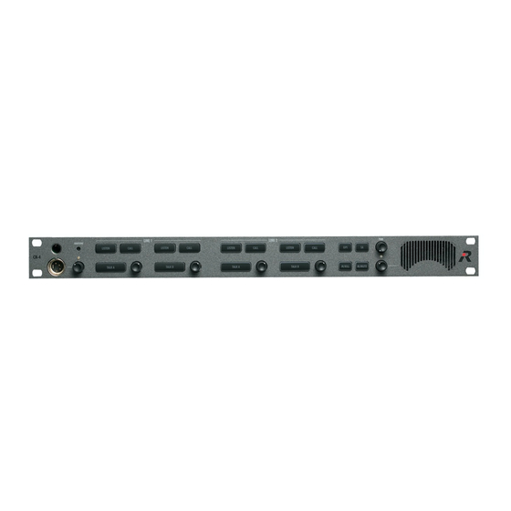
PERFORMER Digital Partyline, User Manual, Version 2.30 3 PERFORMER CR-4 / CR-2 MASTER STATION With the Performer master stations CR-4 (4-channel) and CR-2 (2-channel) it is easy to set up a stand-alone digital partyline system. Depending on the set-up the integrated power supply of the 19”/1RU device can power up to 32 beltpacks. -
Page 10: Microphone Connector
PERFORMER Digital Partyline, User Manual, Version 2.30 3.2.1 Microphone Connector The microphone connector is Riedel’s standard 6.3mm microphone connector for electret microphones, such as MIC 30 / MIC 3. Turn the microphone clockwise to attach the microphone to the unit. -
Page 11: Listen (Latching)
PERFORMER Digital Partyline, User Manual, Version 2.30 3.2.5 LISTEN (Latching) An active LISTEN key (channel key block) enables listening to the related digital partyline channel. If the LISTEN key is deactivated, the LISTEN function of the related partyline is muted. Note: The LISTEN function can also be switched ON / OFF by the LISTEN encoder. -
Page 12: Call (2 Functions)
PERFORMER Digital Partyline, User Manual, Version 2.30 Function TALK Key TALK ON Red 100% TALK OFF (default mode) Red 10% TALK ON but MUTED Red 100% slow flashing TALK OFF and MUTED Red 10% DPL Power Failure (TALK A) Blue 100%, Red 0% 3.2.8 CALL (2 Functions) Light Call (Momentary) -
Page 13: Gpi (Momentary)
PERFORMER Digital Partyline, User Manual, Version 2.30 Settings DIP SW 6 ON CH A ready for GPI Out DIP SW 7 ON CH B ready for GPI Out DIP SW 8 OFF GPI Out by CALL 3.2.9 GPI (Momentary) Activating the GPI key (function key block) closes all GPI Out relay contacts (local & partyline) associated with the active (TALK = ON) digital partyline channels. -
Page 14: Sa Stage Announcement (Momentary)
PERFORMER Digital Partyline, User Manual, Version 2.30 3.2.11 SA Stage Announcement (Momentary) With an active SA (function key block) the microphone signal is routed to the SA output (local 4W) and the related GPI Out relay contact closes ( Pin Out D-Sub). Selection SA Key SA active... -
Page 15: Speaker Volume Knob (2 Functions)
PERFORMER Digital Partyline, User Manual, Version 2.30 3.2.14 Speaker Volume Knob (2 Functions) Speaker Volume The speaker volume rotary encoder adjusts the speaker volume of the unit (0-100%). Turn the encoder clockwise to increase the volume of the speaker and counterclockwise to decrease the volume of the speaker. -
Page 16: User Elements Rear
PERFORMER Digital Partyline, User Manual, Version 2.30 3.3 User Elements Rear Power SUB D PGM In Line 2 DIP Switch Headset Connector Connector Adjustment Line 1 Connector (CR-4 only) PGM In SA Out Line 1 Line 1 Connector Connector Upstream Downstream Connector Connector... -
Page 17: Pgm In Connector
PERFORMER Digital Partyline, User Manual, Version 2.30 SA GPI out Relay The stage announcement SA GPI out closes when the SA key is pressed. GPI out Relay The channel auxiliary GPI of the corresponding partyline closes when the GPI key is pressed AND the DIP switch 6 / 7 is in position ON. -
Page 18: Dip Switch Cr-4 / Cr-2
PERFORMER Digital Partyline, User Manual, Version 2.30 3.3.8 DIP Switch CR-4 / CR-2 Auto momentary Momentary changeover / latched for TALK A. In the ‘Off’ position, a short push on TALK A will switch the microphone signal on channel A ON, a second push switches it OFF again. -
Page 19: Specifications
PERFORMER Digital Partyline, User Manual, Version 2.30 3.4 Specifications Electrical Properties Values Audio bandwidth: 50 Hz – 20 kHz Audio bandwidth (DPL): 50 Hz – 10 kHz Resolution: 16 bit Microphone Preamp: Mic input impedance 1.6 kOhm Dynamic mic input level -52 dBu Electret mic input level -38 dBu... -
Page 20: Performer Cd-2 Desktop Spk/Hs Station
PERFORMER Digital Partyline, User Manual, Version 2.30 4 PERFORMER CD-2 DESKTOP SPK/HS STATION The Performer CD-2 desktop / speaker station can be easily integrated in an existing digital partyline setup with its loop trough connectors. It does not require additional power as it is powered over the line. -
Page 21: Microphone Connector
PERFORMER Digital Partyline, User Manual, Version 2.30 4.2.1 Microphone Connector The microphone connector is Riedel’s standard 6.3mm microphone connector for electret microphones, such as MIC 30 / MIC 3. Turn the microphone clockwise to attach the microphone to the unit. -
Page 22: Listen (Latching)
PERFORMER Digital Partyline, User Manual, Version 2.30 4.2.5 LISTEN (Latching) An active LISTEN key (channel key block) enables listening to the related digital partyline channel. If the LISTEN key is deactivated, the LISTEN function of the related partyline is muted. Note: The LISTEN function can also be switched ON / OFF by the LISTEN encoder. -
Page 23: Call (2 Functions)
PERFORMER Digital Partyline, User Manual, Version 2.30 Function TALK Key TALK ON Red 100% TALK OFF (default mode) Red 10% TALK ON but MUTED Red 100% slow flashing TALK OFF and MUTED Red 10% DPL Power Failure (TALK A) Blue 100%, Red 0% 4.2.8 CALL (2 Functions) Light Call (Momentary) -
Page 24: Gpi (Momentary)
PERFORMER Digital Partyline, User Manual, Version 2.30 Settings DIP SW 6 ON CH A ready for GPI Out DIP SW 7 ON CH B ready for GPI Out DIP SW 8 OFF GPI Out by CALL 4.2.9 GPI (Momentary) Activating the GPI key (function key block) closes all GPI Out relay contacts (local & partyline) associated with the active (TALK = ON) digital partyline channels. -
Page 25: Sa Stage Announcement (Momentary)
PERFORMER Digital Partyline, User Manual, Version 2.30 4.2.11 SA Stage Announcement (Momentary) With an active SA (function key block) the microphone signal is routed to the SA output (local 4W) and the related GPI Out relay contact closes ( Pin Out D-Sub). Selection SA Key SA active... -
Page 26: Speaker Volume Knob (2 Functions)
PERFORMER Digital Partyline, User Manual, Version 2.30 4.2.14 Speaker Volume Knob (2 Functions) Speaker Volume The speaker volume rotary encoder adjusts the speaker volume of the unit (0-100%). Turn the encoder clockwise to increase the volume of the speaker and counterclockwise to decrease the volume of the speaker. -
Page 27: User Elements Rear
PERFORMER Digital Partyline, User Manual, Version 2.30 4.3 User Elements Rear Power Connector SUB D PGM In DIP Switch +48V Connector Adjustment Upstream Downstream SA Out PGM In Connector Connector Connector Connector 4.3.1 Power Connector Connect to this connector the optional external power supply (+48V DC) for refreshing the power of the line or for using the CD-2 as an master station. -
Page 28: Pgm In Connector
PERFORMER Digital Partyline, User Manual, Version 2.30 AUX In + AUX In – Aux Out + AUX Out – GPI Out 1 (Line 2 CH A) GPI Out 1 (Line 2 CH A) GPI Out 2 (Line 2 CH B) GPI Out 2 (Line 2 CH B) Empty Empty... -
Page 29: Downstream Connector
PERFORMER Digital Partyline, User Manual, Version 2.30 4.3.6 Downstream Connector 3-pole male XLR connector - Digital data stream TO the party line (male), optional powered when CD-2 is connected to external power supply. Use this connector to start your partyline or to daisy chain an existing partyline. -
Page 30: Dip Switch Cd-2
PERFORMER Digital Partyline, User Manual, Version 2.30 4.3.8 DIP Switch CD-2 Auto momentary Momentary changeover / latched for TALK A. In the ‘Off’ position, a short push on TALK A will switch the microphone signal on channel A ON, a second push switches it OFF again. -
Page 31: Specifications
PERFORMER Digital Partyline, User Manual, Version 2.30 4.4 Specifications Electrical Properties Values Audio bandwidth: 50 Hz – 20 kHz Audio bandwidth (DPL): 50 Hz – 10 kHz Resolution: 16 bit Microphone Preamp: Mic input impedance 1.6 kOhm Dynamic mic input level -52 dBu Electret mic input level -38 dBu... -
Page 32: Performer C3 Digital Beltpack
PERFORMER Digital Partyline, User Manual, Version 2.30 5 PERFORMER C3 DIGITAL BELTPACK 5.1 Get Started Connect an appropriate headset to the headset connector ( User Elements Bottom). Select the headset microphone type with the DIP switch 5. Now connect the C3 into the partyline by connecting the C3 upstream port ( User Elements Bottom) with the downstream port of the previous device with a 3-pole XLR cable. -
Page 33: Call Led (Orange)
PERFORMER Digital Partyline, User Manual, Version 2.30 5.2.2 CALL LED (orange) The CALL LED lights orange when the CALL key is pressed and TALK is active. If an incoming call is received the CALL LED blinks bright orange alternating with the green LED of the channel being called. -
Page 34: Call Key
PERFORMER Digital Partyline, User Manual, Version 2.30 5.2.6 CALL Key When TALK A or TALK B is active, pressing the CALL key sends a CALL signal to the related channel of the partyline. On all connected devices, the corresponding CALL signal will light up e.g. -
Page 35: Dip Switch Functions
PERFORMER Digital Partyline, User Manual, Version 2.30 5.3.2 DIP Switch Functions Latched/Auto Momentary Switches between momentary and latched for TALK A. In OFF position a short press on the TALK A knob routes the microphone signal to Channel A. Another short press turns it off (Latched). If the knob is pressed and held for longer than 3 seconds it functions as momentary and the channel is closed as soon and the knob is... -
Page 36: Specifications
PERFORMER Digital Partyline, User Manual, Version 2.30 5.4 Specifications Electrical Properties Values Audio bandwidth: 50 Hz – 20 kHz Audio bandwidth (DPL): 50 Hz – 10 kHz Resolution: 16 bit Microphone Preamp: Mic input impedance 1 kOhm Dynamic mic input level -52 dBu Electret mic input level -38 dBu... -
Page 37: Performer Cw-2 Wall Mount Spk / Hs Station
PERFORMER Digital Partyline, User Manual, Version 2.30 6 PERFORMER CW-2 WALL MOUNT SPK / HS STATION The Performer CW-2 Wall Mount Speaker / Headset Station is designed for fixed indoor installations. It comes with a standard plastic 4gang wall mount box. The CW-2 is powered by the digital partyline. -
Page 38: Channel Knob (2 Functions)
PERFORMER Digital Partyline, User Manual, Version 2.30 6.2.1 Channel Knob (2 Functions) Volume Channel A/B The channel volume knob adjusts the channel volume of the CW-2 (0-100%). Turn the knob clockwise to increase the volume of the channel and counterclockwise to decrease the volume of the channel. -
Page 39: Hs Key (Momentary)
Speaker ON, Headset OFF Red 1000% 6.2.6 Microphone Connector The microphone connector is Riedel’s standard 6.3mm microphone connector for electret microphones, such as MIC 30 / MIC 3 (optional). Turn the microphone connector clockwise to attach the microphone to the unit. 6.2.7... -
Page 40: Call Led (Orange)
PERFORMER Digital Partyline, User Manual, Version 2.30 Error LED Channel A CALL LED Channel B Power LED HS / Speaker LED 6.2.9 CALL LED (orange) The CALL LED lights orange when the CALL key is pressed and TALK is active. If an incoming call is received the CALL LED blinks bright orange alternating with the green LED of the channel being called. -
Page 41: Hs Led (Green) / Speaker Led (Red)
PERFORMER Digital Partyline, User Manual, Version 2.30 Status Power LED Powered, ON Red 100% Insufficiently powered, OFF Red 0% 6.2.12 HS LED (green) / Speaker LED (red) These two LEDs indicate if the CW-2 is in headset or speaker mode. Status Headset ON, Speaker OFF Green 100%... -
Page 42: Dip Switch Cw-2
PERFORMER Digital Partyline, User Manual, Version 2.30 6.2.13 DIP Switch CW-2 Latched/Auto Momentary Switches between momentary and latched for TALK A. In OFF position a short press on the TALK A knob routes the microphone signal to Channel A. Another short press turns it off (Latched). If the knob is pressed and held for longer than 3 seconds it functions as momentary and the channel is closed as soon and the knob is... -
Page 43: The Multi-Pin Connector
PERFORMER Digital Partyline, User Manual, Version 2.30 6.3 The Multi-Pin Connector 6.3.1 J100 / J101 Connector Pin Out Connector Values Connect to J100 Cable shield J100 Partyline Upstream + Cable wire J100 Partyline Upstream - Cable wire J100 Cable shield J100 Partyline Downstream + Cable wire... -
Page 44: Connection To 3-Pole Xlr Cable
PERFORMER Digital Partyline, User Manual, Version 2.30 Upstream The upstream connector is for connecting the CW-2 to the preceding piece of equipment on the partyline ( J100 pin out for details). Downstream The downstream connector is for connecting the CW-2 to the next piece of equipment on the partyline ( J100 pin out for details). -
Page 45: Downstream Analogue Input
PERFORMER Digital Partyline, User Manual, Version 2.30 6.3.3 Downstream Analogue Input The downstream connector on the CW-2 can also be used as a local analogue input DIP switch 6, 7 Connector Values Connect to J100 Cable shield J100 Audio In + Cable wire J100 Audio IN -... - Page 46 PERFORMER Digital Partyline, User Manual, Version 2.30 Power Supply: Output voltage with optional C31 PS Output current Power requirements 36-48 V DC Power consumption 180mA @ 48 V Dimensions: H x W x D 134 (5,3) x 223 (8,8) x 44 mm (1,7 inch) Page 46...
-
Page 47: Performer C31 Split Box
PERFORMER Digital Partyline, User Manual, Version 2.30 7 PERFORMER C31 SPLIT BOX The C31 is used to create splits in the digital partyline. The audio signals are processed entirely digitally by DSP chips. The C31 is normally powered by the digital partyline. With its external power connector the C31 enables the insertion of additional power (optional C31 PSU) into the partyline to compensate for power loss due to long cable runs. -
Page 48: Power Led
PERFORMER Digital Partyline, User Manual, Version 2.30 7.1.2 Power LED The power LED indicates if the C31 is powered either over the partyline or via the external power supply. Status Power LED Powered correctly Green 100% No Power Green 0% 7.1.3 Pin Out DC ext. -
Page 49: Specifications
PERFORMER Digital Partyline, User Manual, Version 2.30 7.3 Specifications Electrical Properties Values Audio bandwidth (digital partyline): 50 Hz – 10 kHz Resolution: 16 bit Supply voltage: 20 V – 50 V DC Mechanical Properties Height 44mm (1.75”) Width 105mm (4.1”) Depth 107mm (4.2”) Weight... -
Page 50: Performer C44 / C44Plus System Interface
PERFORMER Digital Partyline, User Manual, Version 2.30 8 PERFORMER C44 / C44PLUS SYSTEM INTERFACE The C44 / C44plus drives up to 4 partylines. Through the integrated 2-wire/4-wire converter it enables digital connections to an Artist/Performer matrix intercom system over a CAT-5 cable using the Artist I/O ports. -
Page 51: Basic Configuration
PERFORMER Digital Partyline, User Manual, Version 2.30 8.1.2 Basic Configuration If the C44 / C44plus is connected to an intercom system via the Artist Digital I/O ports on the rear of the unit the I/Os should be connected one-to-one. Example: The audio signal is split to the connectors I/O 1, partyline 1 and analog 1 a/b. -
Page 52: Dip Switches
PERFORMER Digital Partyline, User Manual, Version 2.30 Pin Out RJ45- Connector (Front) Signal Audio IN + Audio IN - Audio OUT + Audio OUT - Audio RJ45 8.2.4 DIP Switches The DIP switches are only active during stand-alone operation. They are used to select between eight preset configurations. -
Page 53: Serial Interface Rs232 - D-Sub 9 Connector (C44 Only)
PERFORMER Digital Partyline, User Manual, Version 2.30 Pin Out DC in / DC out RJ 45 Signal DC in / DC out RJ 45 8.3.3 Serial Interface RS232 - D-SUB 9 Connector (C44 only) This port is for the Audio Assignment Software ( see AAS manual for details) Page 53... -
Page 54: Gpio Interface
PERFORMER Digital Partyline, User Manual, Version 2.30 8.3.4 GPIO Interface Using the GPIO interface each partyline can send and receive the commands CALL A, CALL B, and Mic Kill. Pin Out: GPI In - D-SUB 25 Connector Signal GPI Function IN1 + CALL A Line #1 IN2 +... - Page 55 PERFORMER Digital Partyline, User Manual, Version 2.30 Pin Out: GPI Out - D-SUB 25 Connector Signal GPO Function OUT1 A CALL A Line #1 OUT2 A CALL B Line #1 OUT3 A SCALLA Line #1 OUT4 A CALL A Line #2 OUT5 A CALL B Line #2 OUT6 A...
-
Page 56: Artist Digital I/O Ports
PERFORMER Digital Partyline, User Manual, Version 2.30 8.3.5 Artist Digital I/O Ports Use the Artist Digital I/O ports of the C44 / C44plus to connect the digital partyline to an Artist or Performer matrix. This enables the user of the matrix to speak directly to the digital partyline and vise versa in digital audio quality. - Page 57 PERFORMER Digital Partyline, User Manual, Version 2.30 Notes: The DIP switch with the highest number has the highest priority. When connected to an Artist system, the DIP switches are not active. When DIP switch 8 is selected, NO cross point is active. In this mode, the C44 / C44plus functions as a pure power supply for four digital partylines.
- Page 58 PERFORMER Digital Partyline, User Manual, Version 2.30 DIP switch 1 set to "ON": DPL1 to Analog1 and Artist I/O 1 DPL2 to Analog2 and Artist I/O 2, and so on Inputs Output Page 58...
- Page 59 PERFORMER Digital Partyline, User Manual, Version 2.30 DIP switch 2 set to "ON": All lines are connection to one another Inputs Outputs Page 59...
- Page 60 PERFORMER Digital Partyline, User Manual, Version 2.30 DIP switch 3 set to "ON": DPL1 is connected to DPL2 + DPL3 + DPL4 DPL1 is connected to Analog 2 +3 +4 Inputs Outputs Page 60...
- Page 61 PERFORMER Digital Partyline, User Manual, Version 2.30 DIP switch 4 set to "ON": DPL1 + DPL2/Analog 1 + 2 are connected DPL3 + DPL4 are routed to their own analog connectors Inputs Outputs Page 61...
- Page 62 PERFORMER Digital Partyline, User Manual, Version 2.30 DIP switch 5 set to "ON": DPL1 + Analog 1 are connected to DPL2 + Analog 2 DPL3 + Analog 3 are connected to DPL4 + Analog 4 Inputs Outputs Page 62...
- Page 63 PERFORMER Digital Partyline, User Manual, Version 2.30 DIP switch 6 set to "ON": DPL1 is connected to 2 + 3 + Analog 2 + 3 DPL2 is connected to 1 + 3 + Analog 1 + 3 DPL3 is connected to 1 + 2 + Analog 1 + 2 Inputs Outputs Page 63...
- Page 64 PERFORMER Digital Partyline, User Manual, Version 2.30 DIP switch 7 set to "ON": DPL1 is connected to Artist 1 and Analog 1 DPL2 is connected to Artist 2 and Analog 2, and so on Inputs Outputs Page 64...
-
Page 65: Specifications
PERFORMER Digital Partyline, User Manual, Version 2.30 8.5 Specifications Electrical Properties Values Audio bandwidth: 50 Hz – 20 kHz Audio bandwidth (DPL): 50 Hz – 10 kHz Resolution: 16 bit Input voltage 100V-240V AC Power Supply Power consumption 250VA max. Input frequency 50-60 Hz Output voltage... -
Page 66: System Layouts
PERFORMER Digital Partyline, User Manual, Version 2.30 9 SYSTEM LAYOUTS 9.1 Stand Alone The following setups give examples of how to setup a digital partyline system. Basic Set-up Master Station Set-up Page 66... -
Page 67: Integration With Artist/Performer Matrix
PERFORMER Digital Partyline, User Manual, Version 2.30 9.2 Integration with Artist/Performer Matrix Integrate your digital Performer partyline seamlessly with your Artist/Performer intercom matrix by using the C44 / C44plus system interface. The C44 / C44plus provides four CAT-5 connectors (Artist I/O) on the rear corresponding with the four digital partyline lines ( C44 / C44plus rear connectors). -
Page 68: Director Setup
If not already installed, install the CAT-5 client card in the correct bay by selecting the CAT-5 client card from the ‘Card Type’ pull down menu. For proper operation of the Performer partyline with a Riedel matrix intercom system the client card software Version 5107Qxx or higher is required. ( Director Manual – Client Card Setup) Once the client card is installed, click on the corresponding client card port where the first C44 / C44plus Artist port is connected to. -
Page 69: Call To Conference
PERFORMER Digital Partyline, User Manual, Version 2.30 For two-channel mode (both digital partyline channels should correspond with the matrix), make a right click on the ‘C3- Beltpack’ now visible in the left ‘Network’ tab window and open the ‘Properties’ menu. Here check the ‘Enable 2nd audio channel’. This automatically blocks the next even-numbered port in the ‘Port List’... - Page 70 PERFORMER Digital Partyline, User Manual, Version 2.30 Once the conference is created, open the ‘Ports’ view. Now double click on the partyline line you want to configure (e.g. C3 Beltpack Line #1 A/B). On the right window, a C3 beltpack appears representing the entire partyline.
- Page 71 PERFORMER Digital Partyline, User Manual, Version 2.30 To add a function to the right TALK key channel B (second partyline channel), make a right click on the second TALK key and select ‘Add function’. Now choose ‘Call to Conference’ from the menu and select the conference you want to speak to from the partyline.
-
Page 72: Gain Adjustment
PERFORMER Digital Partyline, User Manual, Version 2.30 9.2.4 GAIN Adjustment In the properties of the partyline the input and output gain of the partyline can be adjusted. 9.3 Integration with 3rd Party Matrix Integrate your digital Performer partyline with any 3 party intercom matrix by using the C44 / C44plus system interface. -
Page 73: General Pin Outs
PERFORMER Digital Partyline, User Manual, Version 2.30 10 GENERAL PIN OUTS 10.1 Headset 4-pole male XLR Connector Signal GND / Screen Microphone + Speaker R- / L- Speaker R+ / L+ 3-pole male XLR 10.2 Digital Partyline 3-pole XLR Connector Signal TX/RX+ , Power+ TX/RX - , Power+... -
Page 74: Cable Specifications
Note: Do not use CAT-5 cross cables or Star Quad cables as the digital partyline will not work properly with these types of cables! For further information on cables, please contact your local dealer or Riedel Service. 11.2 COAX Cable In certain situations it might be more convenient to send the whole digital partyline signal over a single COAX cable instead of a 3-pole XLR cable. -
Page 75: Troubleshooting
PERFORMER Digital Partyline, User Manual, Version 2.30 12 TROUBLESHOOTING Problem Cause Solution C3 / CW-2 Error LED flickers. A defective cable or the Check cable. maximum cable length has been exceeded. Check cable length. Device does not start. A defective cable or the Check cable. - Page 76 The partyline is set-up Incorrect firmware in the Please check the firmware correctly and connected to matrix. and contact Riedel the matrix but the partyline Customer Service. does not start. The C3 cannot talk on the DIP switches 3 and 4 are in Check DIP switches 3 and 4.
-
Page 77: Service
• Your primary point of contact for any service issues is your local dealer. In addition, Riedel Customer Service in Wuppertal, Germany is also available to assist you. Telephone: +49 (0) 202 292 9400 (Monday - Friday, 8am – 5pm, Central European Time) - Page 78 PERFORMER Digital Partyline, User Manual, Version 2.30 NOTES Page 78...
- Page 79 PERFORMER Digital Partyline, User Manual, Version 2.30 NOTES Page 79...
- Page 80 Riedel Communications Australia Pty.Ltd. • 68/45-51 Huntley Street • Alexandria 2015, Australia Phone +61 (0) 2 9550 4537 • sales-australia@riedel.net Riedel Communications Inc. • 1721 Victoria Blvd• Glendale, CA 91201• USA Phone +1 (914) 819-0495 (East Coast) • Phone + 1 (818) 241 4696 (West Coast) • sales-us@riedel.net www.riedel.net...
Need help?
Do you have a question about the Performer CR-4 and is the answer not in the manual?
Questions and answers