Table of Contents
Advertisement
Quick Links
S/M No. : VK653NTEF0
Service Manual
TIME LAPSE VCR
Model: DV3K653NZ-T
Caution
: In this Manual, some parts can be changed for improving, their
performance without notice in the parts list. So, if you need the
latest parts information,please refer to PPL(Parts Price List) in
Service Information Center (http://svc.dwe.co.kr).
DAEWOO ELECTRONICS CO., LTD.
http : //svc.dwe.co.kr
Jun. 2002
Advertisement
Table of Contents

Related Manuals for Daewoo DV3K653NZ-T


Summary of Contents for Daewoo DV3K653NZ-T
- Page 1 : In this Manual, some parts can be changed for improving, their performance without notice in the parts list. So, if you need the latest parts information,please refer to PPL(Parts Price List) in Service Information Center (http://svc.dwe.co.kr). DAEWOO ELECTRONICS CO., LTD. http : //svc.dwe.co.kr Jun. 2002...
-
Page 2: Table Of Contents
TABLE OF CONTENTS SAFETY&PRECAUTIONS ....................2 EXTERNAL VIEWS ......................4 FRONT VIEWS FUNCTION ........................4 REAR VIEWS FUNCTION ........................5 ELECTRICAL ADJUSTMENT ................... 6 SPECIFICATIONS ....................... 7 TIMELAPSE REC/PB SPEED CHART ................9 CIRCUIT OPERATION ....................10 RS-232C ........................15 TROUBLE SHOOTING FLOW CHART ................27 POWER CIRCUIT ..........................27 SERVO-SYSCON CIRCUIT ........................29 u-COM PORT DESCRIPTION .................. -
Page 3: Safety&Precautions
SAFETY&PRECAUTIONS SAFETY CHECK AFTER SERVING Examine the area surrounding the repaired location for damage or deterioration. Observe that screw, parts and wires have been returned to original positions. Afterwards, perform the following tests and con- form the specified values in order to verify compliance with safety standards. 1. - Page 4 SAFETY&PRECAUTIONS 4. Leakage current test Confirm specified or lower leakage current between B(earth ground, power cord plug prongs) and externally exposed accessible parts (RF terminals, antenna termi- nals, video and audio input output terminals, microphone jacks, earphone jacks, etc.) Measuring method:(Power ON) Insert load Z between B(earth ground, power cord plug prongs) and exposed accessible parts.
-
Page 5: External Views
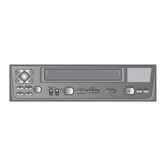
EXTERNAL VIEWS 1. FRONT VIEWS FUNCTION 1) STOP button 13) SET LOCK SWITCH 2) REC button 14) RESET button 3) REC CHECK button 15) MENU button 4) EJECT button 16) SHIFT( ) / TRACKING (-) button 5) CASSETTE LOADING DOOR 17) SHIFT( ) / TRACKING (-) button 6) DISPLAY PANEL 18) REC/PLAY SPEED (-) button (SET - button) -
Page 6: Rear Views Function
EXTERNAL VIEWS 2. REAR VIEWS FUNCTION 1)AC POWER CORD 10)TAPE END terminal 2)WARNING OUT terminal 11)PANIC IN terminal 3)SERIES IN terminal 12)COM terminal 4)COM terminal 13)ALARM OUT terminal 5)SERIES OUT terminal 14)ALARM IN terminal 6)SW OUT terminal 15)MIC (microphone input) jack 7)VIDEO OUT jack 16)AUDIO OUT jack 8)VIDEO IN jack... -
Page 7: Electrical Adjustment
ELECTRICAL ADJUSTMENT 1. SERVO/SYSCON CIRCUIT ADJUSTMENT METHOD v VIDEO HEAD SWITCHING POSITION Adjustment Part Checking Point Measuring Equipment Mode Test Tape TJ396 R595 OSCILLOSCOPE Play DN-1 (Color Bar) PT501 PIN3 v CONNECTION METHOD TJ396 CH-1 Oscilloscope CH-2 R595 PT501 v ADJUSTMENT PROCEDURE 1) Play back the test tape. -
Page 8: Specifications
SPECIFICATIONS-I (20 field-per second with T-160 Tape) 40Hours Real Time Record Mode with T-160 Tape 8000Hour Lifetime guarantee Ball Bearing CAPSTAN MOTOR Mounting DIGITAL SHUTTLE function( REVERSE PLAY & REVERSE SLOW) RS-232C COMMUNICATION PC INTERFACE Up-to 1280 Hours Recording (T-160 Tape) Super Clear Picture - Over 350 Lines Horizontal Resolution(B/W) - Over 300 Lines Horizontal Resolution(Color) - Page 9 SPECIFICATIONS-II Video Signal system NTSC REC/PB System Helical scanning system Tape Width 12.65mm (1/2 inch), VHS Record system of Luminance Signal Frequency modulation record Record system of Color Signal Down converted subcarrier phase shift system 2H : 33.35mm/s (SP), 6H : 11.12mm/s(EP), Tape Speed (T-120) 18H : 3.71mm/s, 36H : 1.85mm/s SP:2/48/72/96/120/168/240/360/480/720/960H,...
-
Page 10: Timelapse Rec/Pb Speed Chart
TIMELAPSE REC/PB SPEED CHART TAPE MODE TAPE SPEED REMARK 120H 168H 240H 360H 480H 720H 960H T-120 MODE 2.7H 128H 160H 224H 320H 480H 640H 960H 1280H T-160 120H 168H 240H 360H 480H 720H 960H T-120 PLAY MODE 2.7H 128H 160H 224H 320H... -
Page 11: Circuit Operation
CIRCUIT OPERATION 1. SERVO SYSCON PART 1-1) BLOCK DIAGRAM LOADING CAPSTAN DRUM CAM DRIVE SPEED CTL PG FG AMP Start end IC501 SENSOR M37775M5H & u-COM REEL PROCESSOR SENSOR BACK OSC& UP BATT RESET AUDIO TERMINAL VIDEO BLOCK BLOCK BLOCK <K682N-T/U SERVO SYSCON BLOCK>... - Page 12 CIRCUIT OPERATION 1-2) TIME LAPSE RECORDING METHOD The numbers of VHS 2HOUR (SP), 6HOUR (EP) REC FIELD are 60 field/sec, then it will be 1FRAME = 33.3Ms, 1FIELD = 16.65Ms. CAPSTAN MOTOR FG numbers for Time Lapse are 6HOUR(EP) = 720 numbers/sec, 2HOUR(SP) = 720*3=2160 numbers/sec.
- Page 13 CIRCUIT OPERATION 1-3) TERMINAL PART ALARM INPUT Connect DOOR SW&SENSOR etc and this port will be used for emergency recording by using open/ close status. N/O(NORMALY OPEN) 500ms N/C(NORMALY CLOSED) 500ms ALARM OUTPUT This port is always triggered during ALARM REC, which is used to inform the outside that time lapse VCR is now performing Alarm Recording.
- Page 14 CIRCUIT OPERATION TAPE END OUT When the recording tape ends during recording, end sensor will be detected. This port is used Alarm to outsider until release the end sensor detecting. END Detect END Detect HIGH SW OUTPUT This port is used triggering video signal with external equipment during recording. VIDEO SIGNAL 1FIELD...
- Page 15 CIRCUIT OPERATION SERIES INPUT When the series recording proceeds after setting the series recording to “on”, this port is used to receive the control signal to the set which will be recorded continuously after pre-recording set. 200ms WARNING OUTPUT This port is used to inform emergency status of Time Lapse VCR Set to outsider. EMERGENCY status term HIGH...
-
Page 16: Rs-232C
RS-232C INTERFACE(RS-232C) 9-pin connector layout Pin number Signal Operation Signal direction Receive data VCR Computer Send data VCR Computer Request to send VCR Computer Signal ground • The signal transmission is compatible with RS-232C specifications. VCR pin number Computer pin number •... - Page 17 RS-232C SECUNET SW INSTALLATION 1. This will install SECUNET on your computer. It is recommended that you exit all other programs before proceed with installation. Click <Next> to continue installation. Or, click <Cancel> to cancel installation.
- Page 18 RS-232C 2. This will be installed to following folder. Click <Install> to begin installation to following folder. To install to a different folder, Either enter install path, Or, click <Browse> and select another folder. space needed: 3,915bytes.
- Page 19 RS-232C 3. Update your file in the screen above and click <Yes>, 4. To complete installation, system must be restarted. Click<Yes>.
- Page 20 RS-232C 5. Click <Confirm>. Connect TimeLapse VCR with PC Necessary articles • 232C Serial Cable (9 pin) • Personal Computer • TimeLapse VCR How to connect • Connect 232C Serial Cable to Com1 of Personal Computer . Problem & Solution If the communication Press RESET button of this set and speed of this set isn’...
- Page 21 RS-232C FUNCTIONS On a screen below, you can control normal operation with remote control. The explanation of the display for each function 1 Title Input Field The character or number which is input in VCR menu is displayed on your PC by RS-232C Communication. 2 Rec speed or Play speed Rec speed is displayed at usual.
- Page 22 RS-232C COMMUNICATIONS SPEED SETTING 1. You can change RS232C communication speed by pressing down menu of setting in above screen. 2. On screen above, click<SETTING> with mouse. Then “ SET” will appea. Click <SET>, so you can control various communication speed like step3.
- Page 23 RS-232C click <OK>. Set the ‘ S PEED and COMPORT’ on small window and Then you can see the changed communication speed and comport. * The communication speed of VCR and Computer is fixed to 9600bps at default value. * The communication comport of Computer is fixed to COM1 at default value. 4.
- Page 24 RS-232C RS-232C Serial commuication Command & Status. 1.command KEY NAME KEY DATA DESCRIPTION PLAY 04 00 02 01 79 STOP 04 00 02 02 78 04 00 02 03 77 04 00 02 04 76 04 00 02 05 75 PAUSE 04 00 02 06 74 EJECT...
- Page 25 RS-232C 2. SINGLE COMMAND & DATA DATA REQUEST PC’ s key requesting Status from VCR The case which DATA from PC to VCR is proper The case which DATA from PC to VCR isn’ t proper 3. STATUS 3.1 NORMAL STATUS 3.1.1 DATA FORMAT <06><40><STATUS1><STATUS2><STATUS3><STATUS4><CHECK SUM>...
- Page 26 RS-232C 3.1.3 STATUS2 BIT DESCRIPTION ErrorCNT 1:EMERGENCY 2: REEL NG 3:DRUM NG 4:SENSOR NG SP : 1 LP,EP:0 REC INHIBIT END SENSOR START SENSOR 3.1.4 STATUS3 BIT DESCRIPTION PWRON REPEAT REC YES SERIES REC YES HIGH PICTURE ALARM REC 3.1.5 STATUS4 BIT DESCRIPTION 0:19200 1:9600 2:4800 PAL_T...
- Page 27 RS-232C <hour> Description about data Status Description hour D6 is 1:MINUS 0:PLUS 3.5 VERSION STATUS 3.5.1 DATA FORMAT <03H><44H><VERSION><CHECK SUM> 3.6 VR DATE STATUS 3.6.1 DATA FORMAT <05H> <45H> <year> <month> <date> <CHECKSUM> 3.7 VR TIME STATUS 3.7.1 DATA FORMAT <06H>...
-
Page 28: Trouble Shooting Flow Chart
TROUBLE SHOOTING FLOW CHART 1. POWER CIRCUIT When changing the parts which are broken first, remove the power plug from the socket and then dis- charge the voltage across the terminals of C806. (Use an external KΩ resistance) When check the primary circuit , use the oscilloscope isolated properly (Use the isolated transformer) and connect GND to the primary GND, however it is not necessary to isolate the oscilloscope when check the secondary circuit. - Page 29 TROUBLESHOOTING FLOW CHART B. CHECKING THE SECONDARY CIRCUIT Check each output voltage Check M801. Check any diode which causes no power Check any COIL, or capacitor which causes no power...
-
Page 30: Servo-Syscon Circuit
TROUBLESHOOTING FLOW CHART 2. SERVO-SYSCON CIRCUIT Playback picture Manual TRK(+),(-) adjust. is not good Noise appears Noise appears Check and re-adjust although although change the path of Deck. adjusting tracking. cassette tape. CTL HEAD height Adjust the HEAD Is CTL pulse output is normal and height and at pin 25 of IC501? - Page 31 TROUBLESHOOTING FLOW CHART Playback picture is not good. Noise appears on the Noise appears on the Check flow A. screen on the whole. screen at the bottom Check the PG Adjustment. Is SW-pulse applied to Is sw pulse supplied Check D.PG input video IC? from pin 18 of IC501? and connector.
- Page 32 TROUBLESHOOTING FLOW CHART Auto-stop during playback. Is reel pulse applied to Check reel sensor. pin 5 and 6 of IC501? Is D. FG applied to Check connector and pin 24 of IC501? D. FG circuits. Check IC501.
- Page 33 TROUBLESHOOTING FLOW CHART Drum M/T loading stops. Is motor 12V supplied Check circuit adjacent from IC 504 pin 7, 8? EVER +12.4V. Check power module. Is 5.2V supplied from Check D814. POWER CIRCUIT? Check connector and motor.
- Page 34 TROUBLESHOOTING FLOW CHART Capstan M/T loading stops. Check power Module. Is motor 12V supplied? Is the input of pin 6 Check circuit of R600, of P501 2.7V~3.7V? R517, R520, C509, C511. Check R525, R526. Is pin 4 of P501 2.5V? Does pin 3 of IC501 Check IC501.
- Page 35 TROUBLESHOOTING FLOW CHART Drum M/T and capstan M/T rotate at irregular speed. (IN REC MODE) Is C. sync applied to Check C. sync of video pin 93 of IC501? IC and pattern. Check motor Emergency mode when plugging (power cord) Is ever 5V applied? Check power Module.
- Page 36 TROUBLESHOOTING FLOW CHART Cassette is not inserted. Check power Module. Is motor 12V supplied? CAM DATA is changed Check connector. when CST IN? Is 5V supplied at Check Deck part. pin 31 of IC501? Check pattern Check IC501. and R572.
- Page 37 TROUBLESHOOTING FLOW CHART Power compensation does not operate. When mains is unplugged, Check C548, C523, is 3.6V at pin 26,pin 81 of IC501? C547, C524. Is (sine) signal applied to Check X502. pin 42 and 43 of IC501? Check reset circuit Is 5V at pin 37 of IC501? Of IC503.
- Page 38 TROUBLESHOOTING FLOW CHART 3. RS232C A. Software Trouble Shoot A-1. Communication speed confirmation Make sure that the communication speed between PC and TIMELAPSE VCR is correspond to each other. A-2. Communication part Confirmation. Communication serial port on PC is made of COM1 and COM2 in general. Make sure that the comport on secunet V1.0 program and that of PC is correspond to each other.
-
Page 39: U-Com Port Description
u-COM PORT DESCRIPTION PORT PORT NAME DESCRIPTION S OUTPUT Series record output S INPUT Series record input C PWM Capstan control D PWM Drum control S REEL Supply reel T REEL Take up reel ARMIN Alarm in BUZ SIG Buzzer sound signal AUDIO 24H (H) Audio 24H Output level control REC MUTE... - Page 40 u-COM PORT DESCRIPTION PORT PORT NAME DESCRIPTION Xout Xout Xout 16MHz out CLKSET Xcin Xcin Xcin 32MHz in Xcout Xcout Xcout 32MHz out DATA Video data Video clock A MUTE (H) Audio Mute HIGH POWER ON(L) PB LOW D SEL Drum select KEY4 Key IN 4...
- Page 41 u-COM PORT DESCRIPTION PORT PORT NAME DESCRIPTION 232TX RS232 TX 232RX RS232 RX TRICK(H) TRICK (H) 232 RTS RS232 RTS WARNING OUTPUT Warning output REC SAFETY Record protect END SENSOR End sensor A/D IN START SENSOR Start sensor A/D IN PWR FAIL (L) Power fail A/D IN F/R ADJ...
-
Page 42: Voltage Chart
VOLTAGE CHART AMP (KA4558 IC502) IC RESET (MN1380L IC503) IC MOTOR DRIVE (BA6209 IC504) 13.6 13.4 13.6 13.4 IC OP AMP (KA4558 IC505) - Page 43 VOLTAGE CHART IC OP AMP (KA4558 IC901) IC RELAY (A9W-K RL901) IC RELAY (A9W-K RL902)
- Page 44 VOLTAGE CHART MICOM IC VOLTAGE CHECK 0.12 0.12 2.76 2.79 2.67 2.68 5.13 5.15 3.81 0.09 5.13 5.15 3.81 3.82 2.22 2.25 3.69 2.97 0.14 0.15 0.87 0.17 5.12 5.15 0.87 0.92 2.76 2.77 0.14 0.17 0.14 0.17 2.94 3.12 0.86 1.07 2.67...
- Page 45 VOLTAGE CHART A/V IC VOLTAGE CHECK 2.45 2.45 2.46 2.45 2.61 2.61 2.52 2.52 0.02 0.02 2.39 2.62 2.62 0.57 5.02 5.02 2.38 2.38 3.69 3.68 2.38 2.38 3.39 3.39 0.01 0.01 5.01 5.01 0.01 0.01 3.32 3.32 1.52 1.49 3.59 3.59 4.22...
-
Page 46: Circuit Diagram
CIRCUIT DIAGRAM 1. CONNECTION DIAGRAM... -
Page 47: Power Circuit Diagram
CIRCUIT DIAGRAM 2. POWER CIRCUIT DIAGRAM... -
Page 48: Syscon Circuit Diagram
CIRCUIT DIAGRAM 3. SYSCON CIRCUIT DIAGRAM... -
Page 49: A/V Circuit Diagram
CIRCUIT DIAGRAM 4. A/V CIRCUIT DIAGRAM... -
Page 50: Osd Circuit Diagram
CIRCUIT DIAGRAM 5. OSD CIRCUIT DIAGRAM... -
Page 51: Logic Circuit Diagram
CIRCUIT DIAGRAM 6. LOGIC CIRCUIT DIAGRAM... -
Page 52: Terminal Circuit Diagram
CIRCUIT DIAGRAM 7. TERMINAL CIRCUIT DIAGRAM... -
Page 53: Components Location Guide On Pcb Bottom View
COMPONENTS LOCATION GUIDE ON PCB BOTTOM VIEW 1. PCB MAIN... -
Page 54: Pcb Union
COMPONENTS LOCATION GUIDE ON PCB BOTTOM VIEW 2. PCB UNION... -
Page 55: Pcb Jack
COMPONENTS LOCATION GUIDE ON PCB BOTTOM VIEW 3. PCB JACK... -
Page 56: Disassembly
DISASSEMBLY 1. PANEL FRONT ASS’ Y... -
Page 57: Set Total Ass' Y
DISASSEMBLY 2. SET TOTAL ASS’ Y... -
Page 58: Packing Ass' Y
DISASSEMBLY 3. PACKING ASS’ Y... -
Page 59: Electrical Parts List
ELECTRICAL PARTS LIST Caution: In this Service Manual, some parts can be changed for improving, their performance without notice in the parts list. So, if you need the latest parts information, please refer to PPL(Parts Price List) in Service information Center. PART=CODE PART-NAME PART-DESC... - Page 60 ELECTRICAL PARTS LIST PART=CODE PART-NAME PART-DESC REMARK PART=CODE PART-NAME PART-DESC REMARK B0600 97S2702600 GEAR L LOADING DURACON M90-02 NATURAL B2140 97S3002900 SPG IDLER SUS304WPB D0.3 B0610 97S2605000 LEVER L LOADING SECC T1.0 A2200 97S3108200 POLYWASHER D2.6XD6.0XT0.5 B0620 97S2605200 LEVER L LOADNIG SUB SECC T1.0 A2300 97S2901600...
- Page 61 ELECTRICAL PARTS LIST PART=CODE PART-NAME PART-DESC REMARK PART=CODE PART-NAME PART-DESC REMARK A3800 7274301011 SCREW TAPPTITE TT3 RND 3X10 MFZN Q801 TKSD2058Y- KSD2058-Y A3900 7274301211 SCREW TAPPTITE TT3 RND 3X12 MFZN Q804 TKSD2058Y- KSD2058-Y A4000 7274300611 SCREW TAPPTITE TT3 RND 3X6 MFZN RL901 5SC0204001 SW RELAY...
- Page 62 ELECTRICAL PARTS LIST PART=CODE PART-NAME PART-DESC REMARK PART=CODE PART-NAME PART-DESC REMARK C327 HCFH104ZBA CHIP CERA 25V Y5V 0.1MF Z 1608 C537 HCBK103KBA CHIP CERA 50V X7R 0.01MF K 1608 C329 HCFH104ZBA CHIP CERA 25V Y5V 0.1MF Z 1608 C538 HCBK103KBA CHIP CERA 50V X7R 0.01MF K 1608 C333...
- Page 63 ELECTRICAL PARTS LIST PART=CODE PART-NAME PART-DESC REMARK PART=CODE PART-NAME PART-DESC REMARK R227 HRFS229JBA R CHIP 1/16 2.2 OHM J 1608 R564 HRFS102JBA R CHIP 1/16 1K OHM J 1608 R228 HRFS229JBA R CHIP 1/16 2.2 OHM J 1608 R571 HRFS101JBA R CHIP 1/16 100 OHM J 1608 R229...
- Page 64 ELECTRICAL PARTS LIST PART=CODE PART-NAME PART-DESC REMARK PART=CODE PART-NAME PART-DESC REMARK R941 HRFS750JBA R CHIP 1/16W 75 OHM J 1608 C520 CEXF1C470A C ELECTRO 16V RSM 47MF (5X7) TP R942 HRFS330JBA R CHIP 1/16 33 OHM J 1608 C521 CEXF1C470A C ELECTRO 16V RSM 47MF (5X7) TP R943...
- Page 65 ELECTRICAL PARTS LIST PART=CODE PART-NAME PART-DESC REMARK PART=CODE PART-NAME PART-DESC REMARK Q504 TZSR1004-- KSR1004 (AUTO) D914 DZUZ5R6BSB IODE ZENER UZ-5.6BSB(5.46-5.70V) Q802 TZSR1004-- KSR1004 (AUTO) D915 DZUZ5R6BSB IODE ZENER UZ-5.6BSB(5.46-5.70V) Q803 TZSR1004-- KSR1004 (AUTO) D916 DZUZ5R6BSB IODE ZENER UZ-5.6BSB(5.46-5.70V) Q901 TZTC3198Y- KTC3198Y-(1815Y) (AUTO) D917 DZUZ9R1BSC...
- Page 66 ELECTRICAL PARTS LIST PART=CODE PART-NAME PART-DESC REMARK PART=CODE PART-NAME PART-DESC REMARK R518 RD-AZ103J- R CARBON FILM 1/6 10K OHM J JP007 85801065GY WIRE COPPER AWG22 1/0.65 TIN COATING R519 RD-AZ103J- R CARBON FILM 1/6 10K OHM J JP008 85801065GY WIRE COPPER AWG22 1/0.65 TIN COATING R521 RD-AZ102J-...
- Page 67 ELECTRICAL PARTS LIST PART=CODE PART-NAME PART-DESC REMARK PART=CODE PART-NAME PART-DESC REMARK JP062 85801065GY WIRE COPPER AWG22 1/0.65 TIN COATING JP118 85801065GY WIRE COPPER AWG22 1/0.65 TIN COATING JP063 85801065GY WIRE COPPER AWG22 1/0.65 TIN COATING JP119 85801065GY WIRE COPPER AWG22 1/0.65 TIN COATING JP064 85801065GY WIRE COPPER...
- Page 68 ELECTRICAL PARTS LIST PART=CODE PART-NAME PART-DESC REMARK PART=CODE PART-NAME PART-DESC REMARK JP172 85801065GY WIRE COPPER AWG22 1/0.65 TIN COATING JP301 85801065GY WIRE COPPER AWG22 1/0.65 TIN COATING JP173 85801065GY WIRE COPPER AWG22 1/0.65 TIN COATING JP302 85801065GY WIRE COPPER AWG22 1/0.65 TIN COATING JP174 85801065GY WIRE COPPER...
- Page 69 ELECTRICAL PARTS LIST PART=CODE PART-NAME PART-DESC REMARK PART=CODE PART-NAME PART-DESC REMARK SW710 5S50101Z90 SW TACT THVV502GDA JP729 85801065GY WIRE COPPER AWG22 1/0.65 TIN COATING SW711 5S50101Z90 SW TACT THVV502GDA JP730 85801065GY WIRE COPPER AWG22 1/0.65 TIN COATING SW712 5S50101Z90 SW TACT THVV502GDA JP731 85801065GY...
- Page 70 ELECTRICAL PARTS LIST PART=CODE PART-NAME PART-DESC REMARK PART=CODE PART-NAME PART-DESC REMARK BA04 7175301012 SCREW TAPPTITE TT2 FLT 3X10 MFZN BLACK 97PB411700 PCB JACK AXIAL DV3K603NZ-JD BA05 7175301012 SCREW TAPPTITE TT2 FLT 3X10 MFZN BLACK C911 CBZP1C103M CERA SEMI 16V Y5S 0.01MF M IC902 1MAX232N-- IC DRIVER...
- Page 71 DAE WOO E LE C TR ONIC S C OR P . 686, AHY E ON-DONG , MAP O-G U, S E OUL, K OR E A. C .P .O. B OX 8003 S E OUL K OR E A P R INTE D DATE : DEC 2002...
Need help?
Do you have a question about the DV3K653NZ-T and is the answer not in the manual?
Questions and answers