Table of Contents
Advertisement
iPA A-SERIES OPERATING MANUAL
The Battery Operated Intermodulation Test System
This document contains information which is confidential and the property of Kaelus, and which is not to be communicated to any person or
company, or used in any way without the previous authorization of Kaelus.
2017 | R99-0090RevF
Advertisement
Table of Contents

Related Manuals for Kaelus IP0703V01B-01N

Summary of Contents for Kaelus IP0703V01B-01N
- Page 1 The Battery Operated Intermodulation Test System This document contains information which is confidential and the property of Kaelus, and which is not to be communicated to any person or company, or used in any way without the previous authorization of Kaelus.
- Page 2 Report Merge functions 1.18.0 31/10/2014 Geo Cache additions. Upload File sizes increased 1.18.1 Addition of iPA Client detail 11200 PDF navigation improvements Rev E 16/04/2017 11141 Warranty section removed In case charging warning Rev F 11319 Implementation of new Kaelus format 27/11/2017...
- Page 3 Precautions WARNING: I N T E R F E R E N C E The IPA family of Test equipment is exempt from the technical requirements of CFR47 part 15 (FCC part 15) as stated in Section §15.103 Exempted devices” for Test equipment per sub part §15.103(c). The following Notice is mandated by Law.
- Page 4 Do not discard any packing material until notified by the carrier or Kaelus. Carefully unpack all containers and check that all items listed on the delivery documentation. Please notify Kaelus of any damaged or missing items from the shipment.
-
Page 5: Table Of Contents
Table of Contents Operating Instructions Introduction Functional Description Features Specifications Construction And Layout Minimum Browser Requirements Equipment Operation – Fixed Frequency Mode 1.7.1 Starting the equipment - iPA 1.7.2 The Main Application Window - iPA 1.7.3 Screen zoom functions (Local Control) 1.7.4 Starting the Equipment –... - Page 6 Operating Manual | The Battery Operated Intermodulation Test System 1.8.11 Editing Measurement Tag Points Equipment Operation - Measurement Modes 1.9.1 Fixed Tone 1.9.2 Frequency Sweep 1.9.3 Spectrum Monitor Mode 1.9.4 Range To Fault Mode (Optional Module) 1.9.5 Eco Mode 1.9.6 Eco mode and Dimmer timer setting 1.9.7 iVA Mode/iPA Mode...
- Page 7 2.4.1 Overview 2.4.2 Enabling WiFi Client Mode 2.4.3 Connecting the iPA to the external wireless access point. 2.4.4 Establishing the IP address of your iPA 2.4.5 Connect your other devices External Wireless access point examples 2.5.1 Enable WEP/WPA security on an external wireless access point 2.5.2 Enable a DHCP Server function 2.5.3...
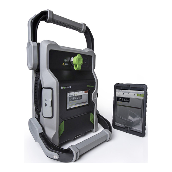
- Page 8 Operating Manual | The Battery Operated Intermodulation Test System List of Figures Figure 1 iPA and Tablet PC Front View Figure 2 Monitor Port, External Wi-Fi Port and DC input socket Figure 3 SD Card, USB and Mini USB Port Figure 4 iPA Start up Window Figure 5 iPA Fixed Frequency Window (Default Measurement Mode) Figure 6 Zoom select region Local control...
- Page 9 Figure 31 Add Measurement Tag Label Figure 32 Mode selection menu Figure 33 Tablet PC PIM vs Time Window Mode (RF “on”) Figure 34 Swept Measurement Window Figure 35 Frequency Step Selection Window Figure 36 IM Order Selection Window Figure 37 Spectrum Analyzer Measurement Window (Local Display) Figure 38 Range to Fault (RTF) Measurement Window Figure 39 Immediate switch to Eco mode (via mode menu) Figure 40 Eco Mode Display...
- Page 10 Operating Manual | The Battery Operated Intermodulation Test System Figure 62 Wi-Fi Settings, Network Selection and Password Menu Figure 63 IP address allocated by the access point. Figure 64 Select WEP Security on external access point Figure 65 Enabling DHCP on External Access Point Figure 66 Manual IP Assignment External wireless acess point example Figure 67 Typical NAT configuration from an intranet Figure 68 Internet connection via VPN...
-
Page 11: Operating Instructions
Introduction This manual describes the operation of the iPA (Interconnect Portable Analyzers) A&B series type of portable intermodulation test instruments developed by Kaelus. The iPA Series Portable Passive Intermodulation (PIM) Analyzer enables measurements of the PIM quality of RF components. The iPA is a fully portable battery powered test instrument, that can be locally controlled using a touch screen interface or remotely controlled via wireless connection to a computer or smart device. -
Page 12: Specifications
Control of a single iVA Cable and Antennae Analyzer via additional Bluetooth module. • Merge and integrate legacy Kaelus *.rpt and current *.zip report files from , iVA , IQA, iPA reports into Client/Head Office ready professional reports. Note 1 : File upload size limit 300Mb, SD card formatted to fat32 filesize limit 2GB... -
Page 13: Construction And Layout
Environmental -10°C to +45°C (Operating) Max. Operating Temperature -10°C to +60°C (Storage) Ingress Protection (IP) IP54. IP67 when enclosed in optional hard case 5% to 95% RH non-condensing Relative Humidity Mechanical Shock 40G shock/vibrating rating Construction And Layout The external details of the iPA test set are shown below in Figure 1 Figure 1 iPA and Tablet PC Front View ©... - Page 14 Operating Manual | The Battery Operated Intermodulation Test System Red LED (RF on indicator) The high intensity, red LED flashes when RF power is present on the RF output Port. RF Output Port The 7/16 RF output port is used for all measurements. Inbuilt Wi-Fi Antenna A 7dBi inbuilt antenna for Wi-Fi connection to the Tablet PC and other Wi-Fi devices.
-
Page 15: Figure 2 Monitor Port, External Wi-Fi Port And Dc Input Socket
Figure 2 Monitor Port, External Wi-Fi Port and DC input socket Monitor Port The Monitor Port performs the following functions: Receiver Monitor Port: Outputs Receiver RF signal spectrum for external Spectrum Analyzer. RTF Mode: Output +12 volts and RF signal spectrum for RTF operation. External Wi-Fi Port Reverse SMA socket available for connecting an external Wi-Fi 5GHz Antenna. -
Page 16: Figure 3 Sd Card, Usb And Mini Usb Port
Operating Manual | The Battery Operated Intermodulation Test System Figure 3 SD Card, USB and Mini USB Port SD Card Port Allows the connection of external memory device (SD Card) for the recording of Reports , State files and Screen Shots. Mini USB Port Accesses the internal memory of the iPA and allows the User to use the iPA as a mass storage device. -
Page 17: Minimum Browser Requirements
Minimum Browser Requirements Supported Browsers are Chrome for Windows and Android environments and Safari under IOS. Early Internet Explorer versions are not supported. Equipment Operation – Fixed Frequency Mode The fixed frequency mode is the default measurement mode of the iPA. In this mode the two test frequencies remain fixed during the duration of the test. -
Page 18: The Main Application Window - Ipa
Operating Manual | The Battery Operated Intermodulation Test System 1.7.2 The Main Application Window - iPA When the instrument is ready to use it will show the Fixed Frequency Window as per Figure 5 below. Figure 5 iPA Fixed Frequency Window (Default Measurement Mode) iPA Initial Fixed Frequency Window features: 1. -
Page 19: Screen Zoom Functions (Local Control)
1.7.3 Screen zoom functions (Local Control) Zoom control is available on the local console for all modes including the RTF option. Zoom control is supported in remote consoles in RTF mode, see the RTF Operating manual for more details. Figure 6 Zoom select region Local control Touch the shaded region to enable the zoom function. -
Page 20: Figure 7 Zoom Adjustment Horizontal (Local Control)
Operating Manual | The Battery Operated Intermodulation Test System 1.7.3.1 Adjusting Horizontal Zoom Figure 7 Zoom Adjustment Horizontal (Local Control) -
Page 21: Figure 8 Zoom Adjustment Vertical (Local Control)
1.7.3.2 Adjusting Vertical Zoom Figure 8 Zoom Adjustment Vertical (Local Control) 1.7.3.3 Adjusting Pan Window Position Reset to return Close When to full Complete Figure 9 Pan Window Adjustment (Local Control) © 2017 Infinite Electronics, Inc., All Rights Reserved. -
Page 22: Starting The Equipment - Samsung Galaxy Tab
Operating Manual | The Battery Operated Intermodulation Test System 1.7.4 Starting the Equipment – Samsung Galaxy Tab Turn on “on” the Tablet PC . Install the Chrome Web Browser or update it to a recent version. This is the preferred browser for use with the iPA. This can be done via the internet on your local Wi-Fi network or mobile phone hotspot. -
Page 23: Starting The Equipment - Ipad
1.7.5 Starting the Equipment - iPAD Turn iPad “on” the iPad Start Up Window will appear as below: Figure 11 iPad Start up Window • Go to iPAD “Settings” menu, • Select Wi-Fi • Set Wi-Fi to “On” • Choose a network TX2131100XXX (Serial No of iPA) •... -
Page 24: Figure 12 Ipad Initial Front Panel Display (Fixed Frequency Window)
Operating Manual | The Battery Operated Intermodulation Test System • iPA Front Panel display should appear on iPad (as below). Figure 12 iPad Initial Front Panel Display (Fixed Frequency Window) iPad Initial PIM Window features: 1. RF “On/Off” button (initially disabled on start-up) 2. -
Page 25: Controlling The Ipa Via Wi-Fi
1.7.6 Controlling the iPA via Wi-Fi To control the iPA with the Tablet PC via the Wi-Fi link, follow the connection procedure below: State/Action iPA Wi-Fi Icon Tablet PC Wi-Fi Icon Description iPA unlocked in Local mode, Tablet PC ready for remote connection Press Control on Tablet PC to transfer Action Button Press control of iPA to the Tablet PC via Wi-... -
Page 26: Return Ipa To Local Mode
Operating Manual | The Battery Operated Intermodulation Test System 1.7.7 Return IPA to Local Mode To return iPA to Local mode and disengage Tablet PC Wi-Fi link, follow the procedure below: State/Action iPA Wi-Fi Icon Tablet PC Wi-Fi Icon Description Press Remote on iPA to return iPA to Action Button Press local operation... -
Page 27: Fixed Frequency Window
1.7.9 Fixed Frequency Window The Fixed Frequency Window is operation is shown below in Figure 13 Figure 13 Browser.iPA Fixed Frequency Window (RF “on”) The Fixed Frequency Window features are explained below: RF ON/OFF Button The RF ON/OFF button is used for switching the RF either on or off. As a visual aid, this button will turn red when the RF has been switched on. - Page 28 Operating Manual | The Battery Operated Intermodulation Test System Reports Menu Reports menu for iPA (see sections 1.10, for details). IP Address for iPA IP Address of iPA (set to 192.168.0.1) Set in Tablet PC Browser window, see Figure 13, Figure 12, Record Button Records instrument settings and Maximum PIM readings during a RF “on”...
- Page 29 may be dragged across with the operator’s finger. RF Power Timer/Settings menu Shows the remaining time before the output power is turned off. Tone Output Power/ Settings Menu The default TX tone output power is 43dBm (20W) per tone, but the power is adjustable to as low as 20dBm (100mW) per tone in 1 dB steps.
-
Page 30: Recalling State Files
Operating Manual | The Battery Operated Intermodulation Test System 1.7.10 Recalling State Files For quick and easy instrument configuration, a state file can be pre-loaded on an SD card. The SD card can be inserted into the SD card slot and the file recalled for setting up the instrument. The setup information is stored in a *.sta file and contains: •... -
Page 31: Shutting Down The Instrument
1.7.11 Shutting down the Instrument 1. To shut down the instrument, press and hold the Power button. A shut-down window will be displayed. Figure 15 Shutdown Window 2. Press OK to initiate the shutdown procedure. The on-board computer will shut down all the internal modules automatically. -
Page 32: Figure 16 Ipa Rf "On" Timer Window
Operating Manual | The Battery Operated Intermodulation Test System Figure 16 iPA RF “on” Timer Window 1. RF “On” Timer setting (Maximum “On” time is 90 seconds) . The RF “on” Timer may be set to a predefined period between 10 and 90 seconds. -
Page 33: Modifying Test Tone Frequency And Power Level
1.8.3 Modifying Test Tone Frequency and Power Level • Press the TX Power icon on the Main Display Window and the TX Tone Powers and frequencies will be displayed. • Press a test tone power field (P1 or P2). A numeric keypad is displayed. •... -
Page 34: Modify The Im Product
Operating Manual | The Battery Operated Intermodulation Test System 1.8.4 Modify the IM Product • Press the IM Product field. The instrument will calculate the various order IM frequencies and a window will be displayed with relevant options. Figure 18 Calculated IM Products •... -
Page 35: Modifying The Im Pass/Fail Threshold
1.8.5 Modifying the IM Pass/Fail Threshold • Press the IM icon at the bottom of the Main Display Window. A Limits Window will be displayed. Figure 19 iPA IM Treshold Level Window 1. IM limit (dBm) or dBc if selected in Miscellaneous Menu 2. -
Page 36: Battery Charge Level Monitor, Monitor Port Gain And System Temperatures
Operating Manual | The Battery Operated Intermodulation Test System 1.8.6 Battery Charge Level Monitor, Monitor Port Gain and System Temperatures • Press the Battery icon at the bottom of the Main Display Window. A Window detailing Battery voltage and monitoring limits will be displayed. -
Page 37: Instrument Settings Menus
1.8.7 Instrument Settings Menus To access the iPA Instrument Settings menu, press the Settings icon at the top of the Main Display Window. 1.8.7.1 Instrument Settings - About Window The Settings About Window details the iPA Model and Build details, Serial No. Software version and calibration dates. It also contains important information of Safety with the unit and Regulatory and Legal stipulations covering the use of the iPA. -
Page 38: Figure 22 Ipa Settings Capabilities Window
Operating Manual | The Battery Operated Intermodulation Test System 1.8.7.2 Instrument Settings - Capabilities Window The Settings Capabilities Window details the Transmitter and Receiver Frequency ranges as well as Battery details including charge level, terminal voltage and shutdown levels. See Figure below. Figure 22 iPA Settings Capabilities Window... -
Page 39: Figure 23 Ipa Settings Region Window
1.8.7.3 Instrument Settings - Region Window The Settings Region Window includes the GUI user language, and date, time and time zone details. See Figure below. Figure 23 iPA Settings Region Window © 2017 Infinite Electronics, Inc., All Rights Reserved. -
Page 40: Figure 24 Ipa Network Settings Window
Operating Manual | The Battery Operated Intermodulation Test System 1.8.7.4 Instrument Settings - Network Window (iPA and Tablet PC) The Network Settings Window on the iPA and the Tablet PC displays Wi-Fi and Ethernet connectivity and allows the user to set the Wi-Fi Access point password, see figures below: Note: Configuring/ restarting the Wi-Fi and Network settings is available on the instrument local display only. -
Page 41: Figure 25 Ipad Settings Menu Selection
1. Current Wi-Fi Hotspot IP address 2. Switch Hotspot mod on or off (Note : the unit can be in either hotspot or client mode or Wi-Fi Off) 3. Switch Wi-Fi enabled (Client mode) on or off. 4. Enter the hotspot settings menu. 5. -
Page 42: Figure 26 Ipad Selecting Your Wi-Fi Hotspot (Serial Number)
Operating Manual | The Battery Operated Intermodulation Test System Figure 26 iPad Selecting your Wi-Fi Hotspot (Serial Number) 1. Select the Wi-Fi menu . 2. Ensure Wi-Fi is switched on . 3. Select your iPA’s Serial number as the network from the list. (Note : Factory default only this can be changed in the hotspot setting on the local display) 4. -
Page 43: Figure 27 Ipad Network Information Windows
Figure 27 iPad Network information Windows 1. Network address allocated to your iPAD from the iPA hotspot. 2. This shows the network address of the router, if the iPA is used as a hotspot this will be 192.168.0.1. 3. This shows the network address of the networks DNS, if the iPA is used as a hotspot this will be 192.168.0.1. ©... -
Page 44: Instrument Settings - Instrument States
Operating Manual | The Battery Operated Intermodulation Test System 1.8.8 Instrument Settings – Instrument States The Instrument State window shows the Test State of the iPA. The Test State may be created, edited and saved by the user to replicate and store instruments states for testing at similar sites. 1.8.8.1 Edit Test State In Configuration mode, the user is able to create new states and recall, rename or delete states. - Page 45 1.8.8.2 Recall a State The instrument setup can be changed by uploading a new state file from the Internal drive of the iPA ,from an SD card. For Android and Windows based controllers the state file can also be uploaded from the controlling devices local drive to the iPA using the Upload key.
-
Page 46: Instrument Settings Miscellaneous Window (Remote Control)
Operating Manual | The Battery Operated Intermodulation Test System 1.8.9 Instrument settings miscellaneous Window (remote control). Figure 29 Miscellaneous settings window 1. Geotagging ON/OFF (Remote control) Note : Location services will need to be enabled on your Tablet PC or SmartPhone and the device will need to have accessed location services sufficient to resolve your location . -
Page 47: Instrument Settings Miscellaneous Window (Local Control)
1.8.10 Instrument settings miscellaneous window (Local control) Scroll down to find Auto Save Screen shot and Power management settings Figure 30 Miscellaneous settings window (Local control) The functions of 2,3,4 are the same as described in Section 1.8.9 © 2017 Infinite Electronics, Inc., All Rights Reserved. -
Page 48: Editing Measurement Tag Points
Operating Manual | The Battery Operated Intermodulation Test System USB storage This enables the iPA to be used as a USB storage device, connect a cable form the mini USB port to your PC and see the files stored on both the SD card or the iPA’s internal memory. Geotag Caching Geotag data provided by a remote control device can be cached on the iPA. -
Page 49: Figure 31 Add Measurement Tag Label
Figure 31 Add Measurement Tag Label 1.8.11.2 Modify a Measurement Tag Label • Select the label to be modified. • Select the label title at the top of the screen. A key board will be displayed. • Enter the new title and press Return. •... -
Page 50: Equipment Operation - Measurement Modes
Operating Manual | The Battery Operated Intermodulation Test System Equipment Operation - Measurement Modes The measurement modes offer added IM measurement and diagnostics capability. The measurement modes presently offered are Fixed Tones. Swept Tones, Spectrum Monitor and Range to Fault (RTF) mode. Note: The user needs to take due care in ensuring that no unlicensed broadcasting of the TX carriers occurs. -
Page 51: Figure 33 Tablet Pc Pim Vs Time Window Mode (Rf "On")
Figure 33 Tablet PC PIM vs Time Window Mode (RF “on”) Figure Figure 33 shows a screen shot of the PIM vs Time measurement window. The shown trace is typical of a loose connector under dynamic testing (percussive tapping). 1. RF “On/Off” button – (Red: RF “On”, Green: RF “Off”) 2. -
Page 52: Frequency Sweep
Operating Manual | The Battery Operated Intermodulation Test System 1.9.2 Frequency Sweep The Swept Tones mode is particularly useful for highlighting anomalies in IM performance within a specific receive band. The instrument measures the vector sum of all PIM sources present on an RF path. If two PIM sources of approximately equal magnitude are present on the RF path and are physically separated in such a way that the two signals arrive at the PIM test equipment exactly 180⁰... -
Page 53: Figure 35 Frequency Step Selection Window
Figure 35 Frequency Step Selection Window The figure below shows the IM order selection window. If a particular order IM band is present within the instruments receive band, it will be displayed. © 2017 Infinite Electronics, Inc., All Rights Reserved. -
Page 54: Spectrum Monitor Mode
Operating Manual | The Battery Operated Intermodulation Test System Figure 36 IM Order Selection Window The user is at liberty to record the peak IM level of a test point at any time during the active frequency sweep. Alternatively, if the set measurement interval is allowed to expire, the user will have the option to save the peak result to the test report. -
Page 55: Figure 37 Spectrum Analyzer Measurement Window (Local Display)
Figure 37 Spectrum Analyzer Measurement Window (Local Display) An added feature in the spectrum monitor mode is the option to switch the RF on. In practical terms, this feature allows the user to see interference in the proximity of an IM signal. (Note: This feature is due to be released for the iPA at a future date). -
Page 56: Range To Fault Mode (Optional Module)
Operating Manual | The Battery Operated Intermodulation Test System 1.9.4 Range To Fault Mode (Optional Module) The Range to Fault mode offers an added analysis tool and is designed to determine the physical distance to the PIM fault from the iPA test set. Details on the operation of the RTF test set is given in the RTF operating manual: R99-0068-RTF_A-SERIES_OPERATING_MANUAL_RevB.doc Figure 38 Range to Fault (RTF) Measurement Window... -
Page 57: Eco Mode
1.9.5 Eco Mode Eco Mode offers a battery saving feature. Eco mode will power down the iPA’s instrument RF stages when not in use, helping to extend the battery life. Remote control and hotspot functions are still active, so the user can still access all the report functions and data while the iPA is in Eco Mode. -
Page 58: Figure 40 Eco Mode Display
Operating Manual | The Battery Operated Intermodulation Test System Figure 40 Eco Mode Display To return to your measurement use the mode button and select the desired measurement mode again. -
Page 59: Eco Mode And Dimmer Timer Setting
1.9.6 Eco mode and Dimmer timer setting Figure 41 Eco Mode and Screen Dimming timer menu Scroll down to find Screen and Eco-mode timeout settings Note : The local dimmer timer is reset once the screen has been touched. The Eco-mode timer is reset if thereis a mode change or measurement made. -
Page 60: Iva Mode/Ipa Mode
Operating Manual | The Battery Operated Intermodulation Test System 1.9.7 iVA Mode/iPA Mode Allows for control of a single iVA Cable and Antenna Analyser via an optional Bluetooth module. Toggles between iVA and iPA control modes . See the R99-0126. iPA/iTA_Supplement_Manual-iVA_CABLE&ANTENNA-Anaylzer Figure 42 iVA measurement modes 1.10... -
Page 61: Customizing Your Report Contractor Name, Details And Logo
1.10.2 Customizing your report Contractor Name, Details and logo Enter the Settings/Report Menu to see the following screen Enter contractor name here Enter contractor details here Select your custom logo file Note : Custom logo files can be added to the extrernal SD card or uploaded to the iPA from a remote control tablet or PC Browser. -
Page 62: Setting Up The Site Test Report
Operating Manual | The Battery Operated Intermodulation Test System 1.10.4 Setting up the Site Test Report The site test report should be set up before any measurements are made. 1. Press the Reports button. The Report window will be displayed. Figure 43 Report Window 2. -
Page 63: Taking An Rf Measurement And Adding Measurement Tags
1.10.5 Taking an RF Measurement and Adding Measurement Tags 1. Before connecting the Device Under Test (DUT) to the Output Port, ensure that all mating surfaces are clean and free of physical defects. Ensure that the connection is adequately tightened. 2. -
Page 64: Figure 45 Removing Measurement Tags
Operating Manual | The Battery Operated Intermodulation Test System Figure 45 Removing Measurement Tags 3. Choose the label for the point in the system at which you are doing the testing and press Return. The chosen Test Point label will be displayed at the top of the test screen, and in the report next to the associated measurements. 4. -
Page 65: Figure 46 Default Measurement Window
Figure 46 Default Measurement Window The RF power can be switched off by pressing the red RF ON button and it will return to green. If you want to record the peak measurement on the report before switching off the RF, press the Record Test Point button. The RF power will also turn off when the RF Timer reaches zero. -
Page 66: Viewing A Test Report
Operating Manual | The Battery Operated Intermodulation Test System 1.10.6 Viewing a Test Report Reports are can be saved to the iPA in a compressed *.zip format. 1. From the user screen, press the Report button. 2. The report screen will be displayed. Figure 47 Report Browsing Window Navigation in the report directory screen is done as follows: 1. -
Page 67: Figure 48 Report Window Items Expanded
Figure 48 Report window items expanded © 2017 Infinite Electronics, Inc., All Rights Reserved. -
Page 68: Saving Reports
Operating Manual | The Battery Operated Intermodulation Test System 1.10.7 Saving Reports Test reports can be saved internally in the iPA, to an SD card or Downloaded in a compressed .zip or PDF format. 1. Insert the SD card if required. 2. -
Page 69: Saving Ipa Screen Shots For Inclusion In Reports
1.10.8 Saving iPA screen shots for inclusion in reports Figure 50 Screen shots local display to be added to reports 1.10.9 Saving iPA screen shots (Not included directly in reports) If you are already using your iPA via remote control , each of your remote control devices will have a different way to do a local screen capture, Print Screen for PC based devices, Android tables often use a combination of home , and Power buttons to do a screen shot as do iPADs , some use power and Volume up, refer to you control devices user manual. -
Page 70: Figure 51 Local Screenshot Touch Point (Not For Inclusion In Report)
Operating Manual | The Battery Operated Intermodulation Test System Figure 51 Local Screenshot touch point (Not for inclusion in report) Touch and hold the settings button for 1 sec and release to enter the screenshot menu.. For standard mode (Autosave off) the following menu will appear. -
Page 71: Moving Items Around In A Report
1.10.10 Moving items around in a report See Figure 47 Report Browsing Window. To locate the move control beside the item you want to shift. Select Move , once highlighted press in the new location for the item. 1.11 Uploading and downloading reports, files and Photos Figure 52 Upload and Download menu ©... -
Page 72: Uploading Files To The Ipa
Operating Manual | The Battery Operated Intermodulation Test System 1.11.1 Uploading files to the iPA First your remote device needs to be in control, see 1.7.6. There are several ways to upload files to the iPA, via the settings/miscellaneous menu See Figure 52 Select the upload key, a file dialogue will appear on the remote control device, a filename can then be selected, this will be as per the local operating system , Apple , Windows , Android . -
Page 73: Figure 54 Uploading Files From The Open Report Menu
Figure 54 Uploading files from the open report menu 1. After the desired directory is selected press Upload, if you are using a Windows or Android controller you will get a local file dialogue and you can select the report *.zip file to upload and open. IOS devices will not permit *.zip file uploads. -
Page 74: Uploading Photos Into Reports
Operating Manual | The Battery Operated Intermodulation Test System 1.11.2 Uploading photos into reports Figure 55 Uploading photos into reports Depending on your tablet or smartphone operating system the screens will look slightly different when the photo option is selected, the operating system will give you the option to upload an existing photo file from the device or to take the photo directly from the tablet or smartphone. -
Page 75: Pdf Report Layout
1.12 PDF report layout Figure 56 PDF Report Layout 1. Contractor Logo 2. Contractor name and details 3. Recorded test result 4. Photo tag/s 5. Photo comment 6. Plot tag/s 7. Plot comment 8. Device state report header 9. Testing device details ©... -
Page 76: Connection Options
Operating Manual | The Battery Operated Intermodulation Test System 2. Connection Options iPA as an Access Point Figure 57 Wi-Fi Connection Options (iPA hotspot) 1. This is a nice and easy configuration with the iPA in hotspot mode connecting to the Serial number as a network 192.168.0.1 in your browser and kaelusap as a default Wi-Fi password. -
Page 77: Tablet Or Smartphone As An Access Point
Tablet or Smartphone as an Access Point Figure 58 Wi-Fi Connection Options (Smartphone hotspot) 1. This is a nice way to use geolocation services, particularly if your phone also has a GPS (Global Positioning System) receiver built in. Remember to setup your phone to share it’s location. 2. -
Page 78: Connect To Iva Via Additional Bluetooth Interface
If you are using an Android tablet with Bluetooth Hardware . The Android app is available via the Play store, search for Kaelus iVA . The iVA Android Manual (R99-0105 - ANDROID_ iVA_OPERATING_MANUAL) is also available. The Android app provides for control of Multiple iVA’s , you can swap between control of your iPA with the chrome browser window via chrome browser and controlling your iVA/s via the app. -
Page 79: Figure 60 Wi-Fi Connection Options (External Access Point)
Figure 60 Wi-Fi Connection Options (external access point) When using this configuration the IP address of the iPA will be the one allocated to it from the access point. This can be checked by scrolling down in the network menu of the local machines screen 1. -
Page 80: Ipa Client Connection Mode
Operating Manual | The Battery Operated Intermodulation Test System iPA Client Connection Mode 2.4.1 Overview The iPA can connect as a client to an existing wireless access point. The following aspects of it’s operation need to be considered. 1. Only WEP, WPA network security is supported, enterprise security is NOT supported. 2. -
Page 81: Enabling Wifi Client Mode
2.4.2 Enabling WiFi Client Mode Under the settings menu select Network . Scroll down and turn on the Wifi enabled switch, see item 1 below, this will also turn off the Hotspot enabled switch. Figure 61 Select Wi-Fi enabled (Client mode) 2.4.3 Connecting the iPA to the external wireless access point. -
Page 82: Establishing The Ip Address Of Your Ipa
Operating Manual | The Battery Operated Intermodulation Test System 2.4.4 Establishing the IP address of your iPA Scroll to the top of the Network menu. If you have successfully connected to the external network the name of the external network will appear and the IP address allocated to your iPA by Access Points DHCP service . You will need this address to allow you to connect to your iPA with a remote control device. -
Page 83: External Wireless Access Point Examples
External Wireless access point examples 2.5.1 Enable WEP/WPA security on an external wireless access point Note : All devices will need to support the selected Encryption Protocol. WEP Selected Figure 64 Select WEP Security on external access point 2.5.2 Enable a DHCP Server function DHCP Selected Figure 65 Enabling DHCP on External Access Point Note : If you don’t mind having to check what IP (internet protocol) address is allocated to the iPA, you could stop... -
Page 84: Figure 66 Manual Ip Assignment External Wireless Acess Point Example
Operating Manual | The Battery Operated Intermodulation Test System Figure 66 Manual IP Assignment External wireless acess point example Find the MAC address of the iPA from the hostname shown on the wireless router usually the iPA’s serial number by default and enter the IP address that you want to set in the router . -
Page 85: Outside Connection Via Wireless Router
2.5.3 Outside connection via wireless router Depending on your external wireless access points capabilities there may be several ways to connect to your iPA . To connect to a single iPA most routers provide either a virtual server function or NAT (Network Address Translation) table. Consult with your Network administrator for the preferred method to use. -
Page 86: Mobile Phone As An External Hotspot
Operating Manual | The Battery Operated Intermodulation Test System 2.5.4 Mobile Phone as an external hotspot. Some mobile have the provision to be able to be used as a mobile WiFi Hotspot see Figure 58 Figure 69 Phone connection settings Figure 70 Phone tethering/Portable hotspot Select more Networks Tethering and Portable hotspot... -
Page 87: Figure 71 Select Hotspot Configuration Menu
Figure 71 Select Hotspot configuration menu Figure 72 Select Phone Hotspot menu Configure the Hotspot Enter the configuration menu © 2017 Infinite Electronics, Inc., All Rights Reserved. -
Page 88: Figure 73 Configure Name. Password And Security
Operating Manual | The Battery Operated Intermodulation Test System Figure 73 Configure Name. Password and security Configure the Hotspot... -
Page 89: General Detail
3. General Detail Getting The Best From The Test Equipment There are a number of practices that will allow the best to be gained from the IM test system, especially for taking PIM measurements. Connector & Cable Care • Good quality connectors and test cables are essential for making PIM and return loss measurements •... -
Page 90: Safety Features
Operating Manual | The Battery Operated Intermodulation Test System Safety Features There are several features to enhance the tester’s safety and prevent damage to the instrument. It is important that the operator is aware of these built-in features. Auto-Power Off The RF power is on a ‘Power Timer’... -
Page 91: External Charger
External Charger External Charger is sold separately with Various accessory kits and has specific details for it’s use in user manual R99- 0092-BATTERY_CRADLE_OPERATING_MANUAL Figure 74 External Battery charger (Optional) RTF (Range To Fault) Unit RTF unit is sold separately with Various accessory kits and has specific details for it’s use in user manual R99-0068- RTF_A-SERIES_OPERATING_MANUAL Figure 75 RTF Range to Fault Unit (Optional) ©... -
Page 92: Iva (Cable And Antennae Analyser)
Operating Manual | The Battery Operated Intermodulation Test System iVA (Cable and Antennae Analyser) iVA unit is sold separately with Various accessory kits, a USB bluetooth interface needs to be fitted to the iPA See . there is a manual supplement XXX Figure 76 iVA Cable and Antennae Analyser (Optional) USB Bluetooth interface. -
Page 93: Troubleshooting Guide
• Insert a fully charged battery. • If the above action does not fix the problem the test set should be returned to a Kaelus/Summitek approved service facility. • Note : Battery charging occurs when connected to the charger and the iPA is switched ON. - Page 94 Operating Manual | The Battery Operated Intermodulation Test System • Geotag service providers can gather geo data from several sources. Having more data sources turned on, on your smartphone/Tablet PC being shared with your geotag service provider can improve your chances of an adequate fix. These include GPS (Global Positioning System) switched on and set to share your location (if fitted), Wi-Fi access points that can be received nearby, Cellular Phone tower signals being received nearby for smartphones or phone enabled tablets, and an internet data connection can all assist to get a geotag fix.
-
Page 95: Ce Declaration Of Conformity
Referenced Safety Standard EN 61010-1:2010 EN 61010-030:2010 The design, development and manufacturing of Kaelus Pty Ltd products are controlled by an ISO 9001:2008 certified Quality Management System. Authorised representation within the EU is Kaelus, 1 Aquarius Court, Viking Way, Rosyth, Scotland, KY11 2DW... -
Page 96: End Of Life Statement
Equipment marked with the symbol below (Crossed Out Wheelie Bin) complies with the European Parliament and Council Directive 2002/96/EC (the “WEEE Directive”) in the European Union. Please contact your local Kaelus representative (see next section) at the end of the product’s useful life to arrange its disposal in accordance with your local regulations.
Need help?
Do you have a question about the IP0703V01B-01N and is the answer not in the manual?
Questions and answers