Telephonics RDR-1600 Pilot's Manual

Telephonics RDR-1600 Pilot's Manual

Rdr-1600 series color weather and search and rescue radar
Hide thumbs Also See for RDR-1600:

Advertisement

Pilot's Guide
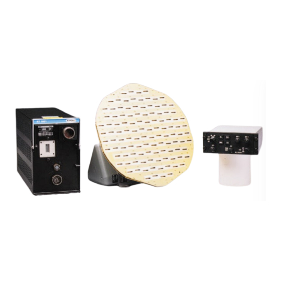
Search and Rescue Radar
Command Systems Division
TM106101
RDR-1600
Color Weather and
August 2001

TABLE OF CONTENTS

PARAGRAPH
1.0
INTRODUCTION . . . . . . . . . . . . . . . . . . . . . . . . . . . .1
2.0
SYSTEM CONFIGURATION . . . . . . . . . . . . . . . . . . .2
2.1
2.2
RADAR DISPLAY INDICATOR . . . . . . . . . . . . . . . . . .4
3.0
OPERATIONAL CONTROLS . . . . . . . . . . . . . . . . . . .5
3.1
CONTROL PANEL . . . . . . . . . . . . . . . . . . . . . . . . .5
3.2
ANTENNA CONTROLS . . . . . . . . . . . . . . . . . . . . . . .6
3.3
DISPLAY CONTROLS . . . . . . . . . . . . . . . . . . . . . . . .6
3.4
PRIMARY MODE SELECTORS . . . . . . . . . . . . . . . . .6
3.5
CONTROLS . . . . . . . . . . . . . . . . . . . . . . . . . . . . . .8
3.6
ALPHANUMERICS . . . . . . . . . . . . . . . . . . . . . . . . . .9
4.0
PREFLIGHT (PFT) . . . . . . . . . . . . . . . . . . . . . . . . . .10
4.1
PREFLIGHT WARNING . . . . . . . . . . . . . . . . . . . . . .10
5.0
THEORY OF OPERATION . . . . . . . . . . . . . . . . . . . .11
5.1
GENERAL . . . . . . . . . . . . . . . . . . . . . . . . . . . . . . . .11
5.2
RADAR PRINCIPLES . . . . . . . . . . . . . . . . . . . . . . .12
5.3
WEATHER RADAR PRINCIPLES . . . . . . . . . . . . . . .13
5.4
RADAR REFLECTIVITY . . . . . . . . . . . . . . . . . . . . . .14
5.5
WEATHER DISPLAY CALIBRATION . . . . . . . . . . . .15
5.6
6.0
WEATHER OPERATIONS . . . . . . . . . . . . . . . . . . . .18
6.1
WEATHER MODE - WX . . . . . . . . . . . . . . . . . . . . .18
6.2
WEATHER ALERT MODE - WXA . . . . . . . . . . . . . .19
6.3
TARGET ALERT . . . . . . . . . . . . . . . . . . . . . . . . . . .19
6.4
6.5
OBSERVING WEATHER . . . . . . . . . . . . . . . . . . . . .20
6.5.1
Thunderstorms and Turbulence . . . . . . . . . . . . . . . .21
6.5.2
Tornadoes . . . . . . . . . . . . . . . . . . . . . . . . . . . . . . . .22
6.5.3
Hail . . . . . . . . . . . . . . . . . . . . . . . . . . . . . . . . . . . . .23
6.5.4
Icing . . . . . . . . . . . . . . . . . . . . . . . . . . . . . . . . . . . . .24
6.5.5
Snow . . . . . . . . . . . . . . . . . . . . . . . . . . . . . . . . . . . .24
6.5.6
Lightning and Static Discharges . . . . . . . . . . . . . . . .24
6.5.7
Range Resolution . . . . . . . . . . . . . . . . . . . . . . . . . . .25
6.5.8
Azimuth Resolution . . . . . . . . . . . . . . . . . . . . . . . . .25
6.5.9
Indicator Resolution . . . . . . . . . . . . . . . . . . . . . . . . .26
6.5.10
Short Range Displays . . . . . . . . . . . . . . . . . . . . . . . .27
6.6
PATH PLANNING . . . . . . . . . . . . . . . . . . . . . . . . . . .28
6.6.1
Path Planning Considerations . . . . . . . . . . . . . . . . . .28
TM106101(8/01)
TITLE
PAGE
i

Advertisement

Table of Contents
loading

Summary of Contents for Telephonics RDR-1600

  • Page 1: Table Of Contents

    PATH PLANNING ......28 Command Systems Division 6.6.1 Path Planning Considerations ....28 TM106101 August 2001 RDR-1600 Pilot’s Guide TM106101(8/01)
  • Page 2 Search 1 ........36 RDR-1600 Pilot’s Guide RDR-1600 Pilot’s Guide...
  • Page 3 Rainfall Rates ......15 of this series of radars. The RDR-1600 series radars are the most popular, advanced capability, multi-mode radars available from any manufacturer.
  • Page 4: System Configuration

    Figure 2.1-1. Receiver- Figure 2.1-2. DA-1203A Drive Transmitter Assembly with AA4512A 12” Flat Figure 2-1. Typical System Block Diagram Plate Antenna Figure 2.1-3. CP-113K Control Panel RDR-1600 Pilot’s Guide RDR-1600 Pilot’s Guide TM106101(8/01) TM106101(8/01)
  • Page 5: Radar Display Indicator

    Beacon Formatting allows for the display of either standard or DO-172 type beacons. This information can be displayed in any of eight separate ranges. RDR-1600 Pilot’s Guide RDR-1600 Pilot’s Guide TM106101(8/01)
  • Page 6: Antenna Controls

    Search 2 – Short range precision mapping. Active on the ten-mile range or less. Search 3 – Normal surface mapping. Beacon mode is compatible with both weather mode and Search mode. RDR-1600 Pilot’s Guide RDR-1600 Pilot’s Guide TM106101(8/01) TM106101(8/01)
  • Page 7: Secondary Mode Selector And Gain Controls

    Figure 3.6-1. MFD Screen Presentations Note MFDs display of radar data will vary by manufacturer. Refer to the MFD Pilot’s Guide for specific radar display. Figure 3.5-1. Secondary Mode Selector and Gain Controls RDR-1600 Pilot’s Guide RDR-1600 Pilot’s Guide TM106101(8/01) TM106101(8/01)
  • Page 8: Preflight (Pft)

    The test pattern scans 120° and automatically selects the 80 mile range. Operational techniques with the RDR-1600 Series Weather Radars are not Look for distinct color bands and range marks in the order shown. Adjust different than with earlier generation radars.
  • Page 9: Radar Principles

    Weather analysis and avoidance are the primary functions of the radar system. transmitted pulse of radar energy to travel out and back from an area of precipitation 10 nautical miles away. Figure 5.2-1. Radar Transmit-Receive Timing RDR-1600 Pilot’s Guide RDR-1600 Pilot’s Guide TM106101(8/01) TM106101(8/01)
  • Page 10: Radar Reflectivity

    0.17-0.5 Moderate 2.5-12 0.1-0.5 (Yellow) possible with lightning Light to moderate turbulence is 0.04-0.17 Weak 0.25-2.5 .01-0.1 (Green possible with lightning Less Less than (Black) than 1 0.04 Figure 5.4-1. Reflective Levels RDR-1600 Pilot’s Guide RDR-1600 Pilot’s Guide TM106101(8/01) TM106101(8/01)
  • Page 11: Weather Attenuation Compensation

    Sensitivity Timing Control (STC) and heavy rain is being seen on radar unless another cell or a ground Extended STC circuitry are employed. The RDR-1600 has an STC range of target can be seen beyond the heavy cell.
  • Page 12: Weather Operations

    Green, Yellow and Red, except that the red returns flash between black and red to draw your attention to the heavier activity. The RDR-1600 will provide you with target information to a greater degree than ever possible on previous generation weather radars. With a 240 nm 6.3 TARGET ALERT...
  • Page 13: Weather Mapping And Interpretation

    6.5.1 Thunderstorms and Turbulence This section contains general information on use of the radar for weather The RDR-1600 weather radar can give you a clue to the presence of interpretation. Review of this information will assist the pilot. turbulence. Areas of the display where the colors change rapidly over a short distance represent steep rainfall gradients, which are usually associ- 6.5 OBSERVING WEATHER...
  • Page 14: Tornadoes

    However, the pilot can be sure that any echo with very ragged edges or rapid changes in shape or intensity will contain severe turbulence. Figure 6.5.3-1. Finger Figure 6.5.3-2. Hook Figure 6.5.3.3. Scalloped Figure 6.5.3-4. U-Shaped Edge RDR-1600 Pilot’s Guide RDR-1600 Pilot’s Guide TM106101(8/01) TM106101(8/01)
  • Page 15: Icing

    The ability of the radar system to resolve closely spaced targets in range areas of heavy icing conditions. However, weather radar has not yet proved depends on transmitter pulse width. In long range modes, the RDR-1600 its ability to distinguish between super-cooled water droplets and ice crys- can distinguish objects spaced as close as 0.19 nm (385 yds.) apart.
  • Page 16: Indicator Resolution

    In the weather mode, the RDR-1600 is unable to ascertain radar returns from close in. On the short range displays, the RDR-1600 paints a red arc in this range to depict the dead band area, as shown in Figure 6.5.10-1.
  • Page 17: Path Planning

    As shown above, the short-range returns show be required. Avoid adjacent cells by at least 20 miles. an obvious corridor between two areas of heavy rainfall, but the long-range setting shows a larger area of heavy rainfall. RDR-1600 Pilot’s Guide RDR-1600 Pilot’s Guide TM106101(8/01) TM106101(8/01)
  • Page 18: Search Operations

    DO regard as severe any thunderstorm with tops 35,000 feet target whose intensity will vary with the degree to choppiness. or higher whether the top is visually sighted or determined by radar. RDR-1600 Pilot’s Guide RDR-1600 Pilot’s Guide TM106101(8/01) TM106101(8/01)
  • Page 19: Looking Angle

    (or radar echo) produced. Illuminating the backslope of hills stretches the area of coverage beyond the flat terrain coverage. RDR-1600 Pilot’s Guide RDR-1600 Pilot’s Guide TM106101(8/01)
  • Page 20: Difference Between Weather And Search Modes

    Use of gain and tilt controls will often improve picture quality. Figure 7.3-1. Wx and SRCH Buttons Figure 7.4.1-1. Search 3 RDR-1600 Pilot’s Guide RDR-1600 Pilot’s Guide TM106101(8/01) TM106101(8/01)
  • Page 21: Search 2

    Figure 7.4.2-1. Search 2 7.4.3 Search 1 Sea clutter rejection effect on ranges of 10 miles or less. Figure 8.1-1. Adjusting the Antenna Tilt Figure 7.4.3-1. Search 1 RDR-1600 Pilot’s Guide RDR-1600 Pilot’s Guide TM106101(8/01) TM106101(8/01)
  • Page 22: Tilt Performance Check

    Figure 8.3-1. Weather Target If target is shown at or beyond the line-of-sight range listed above, the chances are good that it is a weather target. RDR-1600 Pilot’s Guide RDR-1600 Pilot’s Guide TM106101(8/01) TM106101(8/01)
  • Page 23: Antenna Stabilization

    (appearing on the attitude indicators pitch and roll precession accumulate in turns) disappear slowly after the aircraft returns to straight and level. Gyro precession errors directly affect radar stabilization and the quality of the return displayed on the screen. RDR-1600 Pilot’s Guide RDR-1600 Pilot’s Guide TM106101(8/01) TM106101(8/01)
  • Page 24: Beacon Modes

    If the beacon is of the standard format, there will always be only 2 “slash- indicator display. es” on the display spaced 7 nm apart or more. The RDR-1600 can identify any one of nine standard beacons in this mode.
  • Page 25: Multiple Indicators

    Go to the search engine at the bottom of the AC page and enter the title in quotations to find the AC. The RDR-1600 will perform dual scan operation when the range of indica- tor No. 1 (or 2) is greater than or equal to 20 nm and indicator No. 2 (or 1) is less than or equal to 10 nm, and the mode of operation is either search 1 or search 2.
  • Page 26: System Specifications

    Weight: 10”, 0.88 lbs. (4 Kgs), 12”; 1.1 lbs. (0.498 Kgs), 18”; 2.2 lbs. Power Bus One milliamp power drain from 5 Vac (1.0 Kgs) lighting bus (reference). Drive Assembly: 6.5 lbs. (2.95 Kgs) Counterbalanced Drive Assembly: 9.5 lbs. (4.32 Kgs) TSO: C63b RDR-1600 Pilot’s Guide RDR-1600 Pilot’s Guide TM106101(8/01) TM106101(8/01)
  • Page 27 "ride the waves." To reaching maximum intensity during the late afternoon and the first few date, we have no sure way to pick "soft spots" in a thunderstorm. hours of darkness. RDR-1600 Pilot’s Guide RDR-1600 Pilot’s Guide TM106101(8/01) TM106101(8/01)
  • Page 28 Hail may be encountered in clear air several miles from dark (2) At the present time, there is no known operational procedure thunderstorm clouds. that can completely eliminate the possibility of engine damage/flameout RDR-1600 Pilot’s Guide RDR-1600 Pilot’s Guide TM106101(8/01) TM106101(8/01)
  • Page 29 (8) Do regard as extremely hazardous any thunderstorm with tops ing severe weather - not for penetrating it. Whether to fly into an area of 35,000 feet or higher whether the top is visually sighted or determined by radar. RDR-1600 Pilot’s Guide RDR-1600 Pilot’s Guide TM106101(8/01) TM106101(8/01)
  • Page 30 WILLIAM T. BRENNAN the ground. Precautionary signs should be displayed in affected areas to Acting Director of Flight Operations alert personnel of ground testing. RDR-1600 Pilot’s Guide RDR-1600 Pilot’s Guide TM106101(8/01) TM106101(8/01)
  • Page 31: Rdr-1600 Pilot's Guide

    Combustible Materials. To prevent possible fuel ignition, an installed airborne weather radar should not be operated while an aircraft is being refueled or defueled. M.C. Beard Director of Airworthiness AC 20-68B 8/8/80 RDR-1600 Pilot’s Guide TM106101(8/01)
  • Page 32: Appendix

    If the distance (Rs) determined in item b is less than (Ri) found in item a, use distance (Ri) as the minimum safe distance d. If the distance (Rs) determined in item b is greater than (Ri) found in item a, use distance (Rs) as the minimum safe distance RDR-1600 Pilot’s Guide TM106101(8/01)
  • Page 33: Caution

    (2) Distance (Rs) to 1 mw/cm safe limit Rs = π (1250)(5) π = 7.05 meters = 23.1 feet The distance (Rs) is greater than (Ri), therefore, the minimum safe distance is 23.1 feet. RDR-1600 Pilot’s Guide RDR-1600 Pilot’s Guide TM106101(8/01) TM106101(8/01)
  • Page 34 The distance to the MPEL boundary is calculated upon the basis of the largest antenna available with the RDR-1600 system, rated output power of the transmitter and in the non-rotating or boresight position of the antenna. With a scanning beam, the power density at the MPEL boundary is significantly reduced.

This manual is also suitable for:

Cp-113kDa-1203aRt-1601 rt

Table of Contents