Table of Contents
Advertisement
Quick Links
Advertisement
Table of Contents

Related Manuals for ABB EXCOUNT-II


Summary of Contents for ABB EXCOUNT-II
- Page 1 EXCOUNT-II Users manual 2501en EXCOUNT-II Users Manual...
-
Page 2: Safety Instructions
WARNING! All work related to the EXCOUNT-II´s sensors and the surge arresters shall be made with disconnected and earthed conductors. Follow all regulations and rules stated by international or national safety regula- tions. -
Page 3: Table Of Contents
EXCOUNT-II incorporates a sensor, which is mounted on the surge arrester, a transceiver, for remote reading and a PC-program (Windows 95/98/2000/ME and NT). This users manual desribes the functions of EXCOUNT-II to give you total control over surge monitoring. Table of contents 1. -
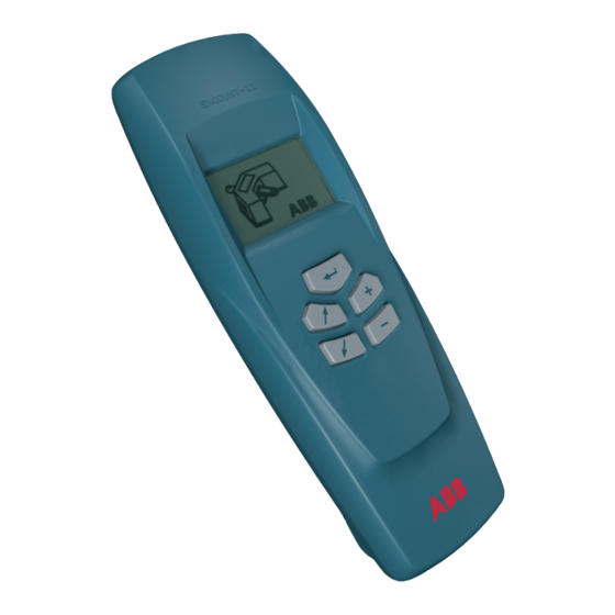
Page 4: Using The Transceiver
To turn off the transceiver press Normal maintenance To achieve the best possible lifetime out of your EXCOUNT-II Transceiver, avoid exposure to strong sunlight for extended periods, hot temperatures (over +50 º C), cold temperatures (under -10 º C ) and water (the design is showerproof but not watertight). -
Page 5: Getting Started
Particulary ensure that the date and clock on the Transceiver are set correctly. Load the EXCOUNT-II software onto your PC and famliarize yourself with its use by reading the individual HELP files within each respective section. Installation/unistallation of software Installation of software Insert the CD into your computer. -
Page 6: Administration Of Sensors
Getting started Administration of Sensors Fit the sensor to the arrester as described in the installation instructions supplied with it. Record the following details as specified in the EXCOUNT-II HELP system for administration: station data arrester data EXCOUNT-II data Input this data into the software as described in the HELP system. -
Page 7: Flowchart, Make Measurements
PC via the data cable via the data cable. Select type of measurement by following the instructions in 1.3. Open the EXCOUNT-II Open the EXCOUNT-II PC- PC software and select "Transfer software and select "Transfer data" followed by data" followed by "Prepare "Receive measured data... -
Page 8: Transceiver Symbols
Transceiver symbols >>>>>>> 2501en EXCOUNT-II Users Manual... -
Page 9: Transceiver Menu System
Set clock and date (see 1.4) Back to stand-by 1.1 Transfer data Select alternative with the key. Then press the Data transfer from PC to Transceiver (see 1.1.1) Data transfer from Transceiver to PC (see 1.1.2) Back to main menu 2501en EXCOUNT-II Users Manual... -
Page 10: Battery Check
In such case download the sensor ID’s again and take new readings. NOTE! Whenever the battery is replaced the transcei- ver clock and date must be reset. (see 1.4) Back to main menu 2501en EXCOUNT-II Users Manual... -
Page 11: Leakage Current Measurement
Start the reading by pressing A successful transmission is marked with A failed transmission is marked with If the transmission was unsuccessful, an error code will be displayed. Progress bar Error code Back to read data menu 2501en EXCOUNT-II Users Manual... - Page 12 NOTE! If the system is 3-phase, the value should be the actual phase-phase voltage. Otherwise, for 1-phase systems, the value should be the phase- ground voltage. The progress bar will indicate that the transmission has begun. * ) Not available in all versions. 2501en EXCOUNT-II Users Manual...
- Page 13 After changing any digit the status symbol is changed to X . When the correct date and clock is set move the cursor to the X and enter the value by pressing This changes the status symbol to 2501en EXCOUNT-II Users Manual...
-
Page 14: Transceiver Error Codes
EEPROM data read error The transceiver could not read from the internal EEPROM memory. Turn off the transceiver and re-start. If the error persists, contact your EXCOUNT-II service representative. EEPROM data write error The transceiver could not write to the internal EEPROM memory. - Page 15 Turn off the transceiver and re-start. If the error persists, error a serious internal fault has occurred with the Transceiver. Contact your EXCOUNT-II service representative. Connection lost The sensor recognised it’s ID but the connection was lost during the transmission. Try re-transmiting again. If the error...
-
Page 16: Sensor Installation
Mount EXCOUNT-II (3) on surge arrester´s bottom flange (4) above insula- ting base (5) according to figure 1 and 2. Do not place close to venting duct (if any). Bolt joint (1 and 2) is supplied with ABB insulating base (5). Fittiing and tightening torque according to instructions supplied with insulating base. - Page 17 Sensor installation Top view Side view EXCOUNT-II is used as earth connection. Connect earth cable with tinplated socket (7) according to figure 2. Recommended screw: M12 (6) Tightening torque for M12: 84 Nm, use washers 2501en EXCOUNT-II Users Manual...
- Page 18 NOTE! Resistive current measurement is not supported with this special application. Mount EXCOUNT-II against planar surface. Use 2 X M6 bolts. Connect upper terminal to flange, bottom terminal to earth via conductor. Recommended screw: M12. Do not mount on earthed plate.
-
Page 19: More Information
More information For more information about EXCOUNT-II and for downloading updates of the EXCOUNT-II software, please visit: http://www.abb.com/arrestersonline Select HIGH VOLTAGE SURGE ARRESTERS (HV) Select EXCOUNT-II 2501en EXCOUNT-II Users Manual... - Page 20 ABB Power Technology Products AB High Voltage Products Surge Arresters SE-771 80 LUDVIKA, Sweden Tel. +46 (0)240 78 20 00 Fax. +46 (0)240 179 83 E-mail: arresters.div@se.abb.com Internet: http://www.abb.com/arrestersonline 2501en EXCOUNT-II Users Manual...
Need help?
Do you have a question about the EXCOUNT-II and is the answer not in the manual?
Questions and answers